EP0291918A2 - Motor ventilation improvement - Google Patents
Motor ventilation improvement Download PDFInfo
- Publication number
- EP0291918A2 EP0291918A2 EP88107854A EP88107854A EP0291918A2 EP 0291918 A2 EP0291918 A2 EP 0291918A2 EP 88107854 A EP88107854 A EP 88107854A EP 88107854 A EP88107854 A EP 88107854A EP 0291918 A2 EP0291918 A2 EP 0291918A2
- Authority
- EP
- European Patent Office
- Prior art keywords
- frame member
- bearing bracket
- aperture
- air
- axially
- Prior art date
- Legal status (The legal status is an assumption and is not a legal conclusion. Google has not performed a legal analysis and makes no representation as to the accuracy of the status listed.)
- Withdrawn
Links
Images


Classifications
-
- H—ELECTRICITY
- H02—GENERATION; CONVERSION OR DISTRIBUTION OF ELECTRIC POWER
- H02K—DYNAMO-ELECTRIC MACHINES
- H02K9/00—Arrangements for cooling or ventilating
- H02K9/02—Arrangements for cooling or ventilating by ambient air flowing through the machine
- H02K9/04—Arrangements for cooling or ventilating by ambient air flowing through the machine having means for generating a flow of cooling medium
- H02K9/06—Arrangements for cooling or ventilating by ambient air flowing through the machine having means for generating a flow of cooling medium with fans or impellers driven by the machine shaft
-
- H—ELECTRICITY
- H02—GENERATION; CONVERSION OR DISTRIBUTION OF ELECTRIC POWER
- H02K—DYNAMO-ELECTRIC MACHINES
- H02K5/00—Casings; Enclosures; Supports
- H02K5/04—Casings or enclosures characterised by the shape, form or construction thereof
- H02K5/10—Casings or enclosures characterised by the shape, form or construction thereof with arrangements for protection from ingress, e.g. water or fingers
Definitions
- housings for rotating electric machinery had utilized a frame and shaft bearing bracket combination to provide an open drip-proof enclosure.
- the frame and shaft bearing brackets were specially designed and suitable only for such open drip-proof applications.
- a new frame member and new bearing brackets were required when a totally enclosed structure was required. This necessitated a separate inventory of such machinery enclosure parts and resulted in additional cost and complexity for rotating electric machinery manufacturers.
- the present invention overcomes these disadvantages of the prior art open drip-proof structures by providing for utilization of totally-enclosed type bearing brackets in a new open drop-proof construction which provides for an air inlet aperture permitting the intake of air above the shaft center line.
- This new construction greatly increases the effective cooling, and reduces the probability of contamination by dirt or other debris resting on the machinery mounting surface in horizontal shaft applications, and reduces the number of parts needed for inventory by allowing the use of totally enclosed bearing brackets in open drip-proof applications.
- the present invention is useful for any electric machinery which uses cooling air, e.g., motors, generators or electromagnetic clutches or brakes.
- a prior art open drip-proof motor enclosure 10 may be seen.
- Enclosure 10 has a frame member 12 and a pair of open drip-proof type bearing brackets 14, 16 each respectively carrying a bearing 18, 20 by which a shaft 22 is mounted for rotation within housing or enclosure 10.
- cooling air passes across rotor mounted fan 34, along stator 36, and exits through ports 38.
- FIG. 2A shows a horizontal shaft electric motor 40.
- Motor 40 has a shaft 42 mounted for rotation by bearings 44, 46 located in bearing brackets 48, 50.
- a rotor 52 is mounted on shaft 42 for rotation therewith.
- Rotor 52 carries fans 54, 56 designed to impel air radially toward a stator 58 located on a frame member 60.
- Frame member 60 has a pair of air flow or inlet rings 62, 64 mounted at opposite ends thereof.
- single-ended cooling may be accomplished by using an air flow ring at only one end of the machinery enclosure. Ring 62 may be seen in an end view in Fig. 2B.
- Frame member 60 further has a plurality of lands or spacers 66 upon which bearing bracket 48 is mounted. Bracket 48 is secured to frame member 60 by bolts 68 secured through lands or bosses 66 which may be formed in one piece with frame 10 or which may be separate pieces. Bearing bracket 50 is secured to frame 60 in a similar fashion. Referring now more particularly to both Figs. 2A and 2C, a plurality of ports 70 are provided to permit the egress of cooling air from motor 40.
- cooling air enters motor 40 between bearing bracket 48 and ring 62 in a generally axial direction. Cooling air next progresses radially inward between surface 72 of frame member 60 and interior surface 74 of bracket 48. Cooling air next passes between a stator shroud or air deflector 76 (formed as a section of a toroidal surface formed of sheet metal, fiberglass or other suitable material) and interior surface 75 of bearing bracket 48. Fan 54 then receives the cooling air flow and directs it radially outward and then generally axially across stator 58. Finally, the cooling air flow exits at ports 70. It is to be understood that fans 54, 56 provide the motive force for cooling air in this design.
- an optional shaft mounted fan 78 may be used to direct air to both stator 80 and rotor 82.
- Rotor 82 has axial passageways 84 and radially passageways 86 for conducting cooling air through rotor 82.
- Stator 80 also may have radial passageways 88 aligned with radial passageways 86.
- a rotor mounted fan 90 may be used in place of or in addition to shaft mounted fan 78.
- ring 62 is omitted from frame member 60′.
- a drip cover 100 preferably formed of sheet metal may be secured to bracket 48 by drive screws or rivets 102 or, alternatively, may be secured to lands or spacers 66 if desired.
- cover 100 may be cast as a single piece with frame member 60′.
- the air outlet ports will be made vertically drip-proof by one or more sheltering members such as louvers or awnings, preferably formed of sheet metal in a conventional manner.
- the air passageway 92 formed between bracket 50 and ring 64 may be made into an air outlet passageway by extending air deflector 94 as shown by the double-dashed lines 96 while at the same time extending fan 56 to the dashed position 98.
- ports 70 may be closed off.
- ports 70 may be used as air inlets and air passageways 92, 93 as air outlets.
Landscapes
- Engineering & Computer Science (AREA)
- Power Engineering (AREA)
- Motor Or Generator Cooling System (AREA)
- Motor Or Generator Frames (AREA)
Abstract
Description
- In the past, housings for rotating electric machinery had utilized a frame and shaft bearing bracket combination to provide an open drip-proof enclosure. In such prior art structures, the frame and shaft bearing brackets were specially designed and suitable only for such open drip-proof applications. A new frame member and new bearing brackets were required when a totally enclosed structure was required. This necessitated a separate inventory of such machinery enclosure parts and resulted in additional cost and complexity for rotating electric machinery manufacturers.
- In addition, such open drip-proof structures, particularly in the bearing brackets, had relatively small inlet air apertures, reducing cooling effectiveness. Finally, such prior art inlet apertures conventionally were located below the shaft centerline, often near the base of such machinery when it was mounted for horizontal shaft operation, thus increasing the possibility of contamination of such machinery by dirt or other foreign material resting on the surface on which such machinery was mounted.
- The present invention overcomes these disadvantages of the prior art open drip-proof structures by providing for utilization of totally-enclosed type bearing brackets in a new open drop-proof construction which provides for an air inlet aperture permitting the intake of air above the shaft center line. This new construction greatly increases the effective cooling, and reduces the probability of contamination by dirt or other debris resting on the machinery mounting surface in horizontal shaft applications, and reduces the number of parts needed for inventory by allowing the use of totally enclosed bearing brackets in open drip-proof applications. The present invention is useful for any electric machinery which uses cooling air, e.g., motors, generators or electromagnetic clutches or brakes.
-
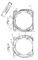
- Fig. 1A shows a section end view of a shaft bearing bracket of prior art construction.
- Fig. 1B shows a side view of a prior art construction partially cut away to show interior air flow.
- Fig. 1C shows a section view of the frame member of Fig. 1B illustrating the exhaust path for cooling air in this prior art structure.
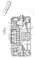
- Fig. 2A shows a partial cut away side view of an embodiment of the present invention illustrating the features of the inlet air flow passageway structure.
- Fig. 2B is an end view of the frame member of Fig. 2A.
- Fig. 2C is a section view through the frame member of Fig. 2A showing outlet air pathways.
- Fig. 3 is a partial cut away side view of an alternative embodiment of rotating electric machinery illustrating the inlet air flow passageway structure of the present invention.
- Fig. 4 is a fragmentary view of a still further alternative embodiment showing a structure suitable for vertical shaft mounting.
- Referring now more particularly to Figs. 1A-C, a prior art open drip-
proof motor enclosure 10 may be seen.Enclosure 10 has aframe member 12 and a pair of open drip-prooftype bearing brackets bearing shaft 22 is mounted for rotation within housing orenclosure 10. Air entersenclosure 10 by way of apertures 24-28 inbracket 14, and by way ofapertures bracket 16. After enteringenclosure 10, cooling air passes across rotor mountedfan 34, alongstator 36, and exits throughports 38. - Referring now to Figs. 2A-C, an open drip-proof version of rotating electric machinery utilizing the present invention may be seen. Fig. 2A shows a horizontal shaft
electric motor 40.Motor 40 has ashaft 42 mounted for rotation bybearings bearing brackets rotor 52 is mounted onshaft 42 for rotation therewith. Rotor 52 carriesfans stator 58 located on aframe member 60.Frame member 60 has a pair of air flow orinlet rings Ring 62 may be seen in an end view in Fig. 2B.Frame member 60 further has a plurality of lands orspacers 66 upon which bearingbracket 48 is mounted.Bracket 48 is secured toframe member 60 bybolts 68 secured through lands orbosses 66 which may be formed in one piece withframe 10 or which may be separate pieces.Bearing bracket 50 is secured to frame 60 in a similar fashion. Referring now more particularly to both Figs. 2A and 2C, a plurality ofports 70 are provided to permit the egress of cooling air frommotor 40. - In this embodiment, cooling air enters
motor 40 betweenbearing bracket 48 andring 62 in a generally axial direction. Cooling air next progresses radially inward betweensurface 72 offrame member 60 andinterior surface 74 ofbracket 48. Cooling air next passes between a stator shroud or air deflector 76 (formed as a section of a toroidal surface formed of sheet metal, fiberglass or other suitable material) andinterior surface 75 ofbearing bracket 48.Fan 54 then receives the cooling air flow and directs it radially outward and then generally axially acrossstator 58. Finally, the cooling air flow exits atports 70. It is to be understood thatfans - Referring now to Fig. 3, an alternative embodiment may be seen. In this embodiment, an optional shaft mounted
fan 78 may be used to direct air to bothstator 80 androtor 82.Rotor 82 hasaxial passageways 84 and radiallypassageways 86 for conducting cooling air throughrotor 82. Stator 80 also may haveradial passageways 88 aligned withradial passageways 86. A rotor mountedfan 90 may be used in place of or in addition to shaft mountedfan 78. - Referring now to Fig. 4, a still further embodiment suitable for vertical shaft applications may be seen. In this embodiment,
ring 62 is omitted fromframe member 60′. Adrip cover 100 preferably formed of sheet metal may be secured tobracket 48 by drive screws or rivets 102 or, alternatively, may be secured to lands orspacers 66 if desired. Alternativelycover 100 may be cast as a single piece withframe member 60′. In vertical shaft applications the air outlet ports will be made vertically drip-proof by one or more sheltering members such as louvers or awnings, preferably formed of sheet metal in a conventional manner. - The invention is not to be taken as limited to all of the details thereof as modifications and variations thereof may be made without departing from the spirit or scope of the invention. For example, the
air passageway 92 formed betweenbracket 50 andring 64 may be made into an air outlet passageway by extendingair deflector 94 as shown by the double-dashedlines 96 while at the sametime extending fan 56 to the dashedposition 98. With such anarrangement ports 70 may be closed off. As a still furtheralternative ports 70 may be used as air inlets andair passageways
Claims (21)
the absence of air flow apertures therethrough;
a frame member (60) mounted to and axially spaced apart from said bearing bracket (48, 50) forming a radially oriented aperture; and
an axially projecting air flow ring (62, 64) radially outwardly from said radially oriented aperture and secured to the assembly of said bearing bracket (48, 50) and said frame member (60) to admit external cooling air to the interior of said machinery.
a. a pair of rings (62, 64) forming axial extensions of a motor frame member (60) at opposite axial ends thereof; and
b. a pair of totally-enclosed shaft bearing brackets (48, 50), each:
i) disposed at an axial end of said frame member (60), and
ii) spaced radially inwardly of said rings (62, 64) to form axially oriented air inlet apertures for passage therebetween of external cooling air entering the interior of said machinery.
Applications Claiming Priority (2)
| Application Number | Priority Date | Filing Date | Title |
|---|---|---|---|
| US53102 | 1987-05-21 | ||
| US07/053,102 US4766337A (en) | 1987-05-21 | 1987-05-21 | Open drip-proof machinery cooling system using totally enclosed type bearing brackets |
Publications (2)
| Publication Number | Publication Date |
|---|---|
| EP0291918A2 true EP0291918A2 (en) | 1988-11-23 |
| EP0291918A3 EP0291918A3 (en) | 1989-07-26 |
Family
ID=21981938
Family Applications (1)
| Application Number | Title | Priority Date | Filing Date |
|---|---|---|---|
| EP88107854A Withdrawn EP0291918A3 (en) | 1987-05-21 | 1988-05-17 | Motor ventilation improvement |
Country Status (5)
| Country | Link |
|---|---|
| US (1) | US4766337A (en) |
| EP (1) | EP0291918A3 (en) |
| DK (1) | DK276588A (en) |
| PL (1) | PL272595A1 (en) |
| PT (1) | PT87500A (en) |
Cited By (4)
| Publication number | Priority date | Publication date | Assignee | Title |
|---|---|---|---|---|
| EP0874442A3 (en) * | 1997-04-22 | 2000-08-09 | Emerson Electric Co. | An electric motor having an improved airflow cooling system |
| WO2010018033A3 (en) * | 2008-07-21 | 2010-04-22 | Siemens Aktiengesellschaft | Electric machine having radial dividers for guiding cooling air |
| RU2457599C2 (en) * | 2010-07-08 | 2012-07-27 | Научно-производственное объединение "ЭЛСИБ" Открытое акционерное общество | Electric machine |
| US9425445B2 (en) | 2011-01-21 | 2016-08-23 | Audi Ag | Battery having a plurality of battery cells |
Families Citing this family (31)
| Publication number | Priority date | Publication date | Assignee | Title |
|---|---|---|---|---|
| JPH03222651A (en) * | 1989-11-06 | 1991-10-01 | Toshiba Corp | Air-cooled induction motor |
| DE4003155A1 (en) * | 1990-02-03 | 1991-08-29 | Bosch Gmbh Robert | ELECTRIC MACHINE WITH FOREIGN VENTILATION |
| US5122154A (en) * | 1990-08-15 | 1992-06-16 | Rhodes Valentine J | Endovascular bypass graft |
| DE4041424C2 (en) * | 1990-12-21 | 1995-03-30 | Lescha Maschf Gmbh | mixer |
| US5182482A (en) * | 1991-05-15 | 1993-01-26 | Siemens Energy & Automation, Inc. | Dynamoelectric machine having improved ventilation |
| US5214324A (en) * | 1992-01-03 | 1993-05-25 | General Electric Company | Stator air baffle |
| US5343101A (en) * | 1992-02-25 | 1994-08-30 | Magnetek Century Electric, Inc. | Plastic air deflector for rotating dynamoelectric machine |
| GB2286293A (en) * | 1993-12-23 | 1995-08-09 | London Innovation Limited | Adjustable stator: winding construction: cooling and commutator construction inan electric machine |
| JPH1075546A (en) * | 1996-08-29 | 1998-03-17 | Sawafuji Electric Co Ltd | Drip-proof structure in power generator |
| US5898246A (en) * | 1998-03-13 | 1999-04-27 | The United States Of America As Represented By The Secretary Of The Air Force | Control of reluctance dynamoelectric machine cooling fluid |
| US20030040790A1 (en) | 1998-04-15 | 2003-02-27 | Furst Joseph G. | Stent coating |
| US6188153B1 (en) * | 1999-02-18 | 2001-02-13 | General Electric Company | Segmented stator end turn air deflector for force ventilated AC motor |
| US6774514B2 (en) * | 2000-02-25 | 2004-08-10 | Kabushiki Kaisha Toshiba | Totally enclosed type driving electric motor |
| US6417595B1 (en) | 2000-05-24 | 2002-07-09 | Mcmillan Electric Company | Spark suppression dust sealing for a motor apparatus |
| US6906440B1 (en) | 2000-06-13 | 2005-06-14 | General Electric Canada, Inc. | Bracket assembly having a plurality of plates for a dynamoelectric machine |
| US6563240B2 (en) * | 2001-04-24 | 2003-05-13 | A. O. Smith Corporation | Electric motor having a rain baffle |
| US6703730B2 (en) * | 2001-05-24 | 2004-03-09 | Asmo Co., Ltd. | Electric motor cooling having air-communication restrain between intake duct and exhaust duct, and having cooling fan received in yoke |
| US6851267B2 (en) * | 2002-12-18 | 2005-02-08 | Pratt & Whitney Canada Corp. | Compact quick attach starter-generator installation |
| DE10349205A1 (en) * | 2003-10-23 | 2005-06-09 | Hilti Ag | Electric motor with air duct |
| DE102004013133A1 (en) * | 2004-03-17 | 2005-10-13 | Siemens Ag | Electric machine with improved cooling and cooling method |
| US20060071567A1 (en) * | 2004-10-01 | 2006-04-06 | Siemens Vdo Automotive Corporation | Plastic molded motor housing |
| US7102266B2 (en) * | 2005-02-08 | 2006-09-05 | Ametek, Inc. | Motor assembly with a sealed commutator/brush interface |
| JP5325475B2 (en) * | 2008-06-23 | 2013-10-23 | 本田技研工業株式会社 | Engine driven generator |
| US20100176670A1 (en) * | 2009-01-12 | 2010-07-15 | Power Group International Corporation | Machine cooling scheme |
| US8975795B2 (en) * | 2010-03-12 | 2015-03-10 | Siemens Aktiengesellschaft | Electric generator |
| CN201774430U (en) * | 2010-07-29 | 2011-03-23 | 中山大洋电机制造有限公司 | A new motor mechanism |
| JP5535014B2 (en) * | 2010-09-09 | 2014-07-02 | 株式会社東芝 | Electric motor |
| BR112014015627B1 (en) | 2011-12-22 | 2021-03-09 | Weg Equipamentos Eletricos S/A | casing for drip-proof open type rotating electrical machines |
| CN102840085A (en) * | 2012-09-07 | 2012-12-26 | 潮州市汇能电机有限公司 | Shaft extension tubular hydrogenerator |
| US9306432B2 (en) * | 2012-10-31 | 2016-04-05 | Hamilton Sundstrand Corporation | Stator cooling channel tolerant to localized blockage |
| EP3496240B1 (en) * | 2016-08-05 | 2022-02-23 | Nidec Corporation | Motor and axial flow fan |
Family Cites Families (13)
| Publication number | Priority date | Publication date | Assignee | Title |
|---|---|---|---|---|
| DE560135C (en) * | 1932-09-29 | Aeg | Ventilation device for the winding heads of induction motors | |
| US1961387A (en) * | 1930-08-19 | 1934-06-05 | U S Electrical Mfg Company | Ventilated motor |
| US2074067A (en) * | 1935-10-14 | 1937-03-16 | Master Electric Co | Ventilated splashproof motor housing |
| US2347517A (en) * | 1942-07-01 | 1944-04-25 | Gen Electric | Dynamoelectric machine |
| US2419156A (en) * | 1944-11-10 | 1947-04-15 | Westinghouse Electric Corp | Motor |
| FR1059751A (en) * | 1947-07-19 | 1954-03-29 | Electro Mecanique De Laveyron | Improvements in cooling means of electrical devices, in particular electrical brakes |
| US2522675A (en) * | 1948-09-15 | 1950-09-19 | Vaino A Hoover | Ventilating means for electric motors |
| US3027470A (en) * | 1958-11-05 | 1962-03-27 | Fairbanks Morse & Co | Cooling passage means for dynamoelectric machines |
| US3021442A (en) * | 1958-12-26 | 1962-02-13 | Ford Motor Co | Dynamoelectric machine |
| US3512024A (en) * | 1968-08-19 | 1970-05-12 | Westinghouse Air Brake Co | Frameless permissible dynamoelectric machine |
| US3518467A (en) * | 1968-11-04 | 1970-06-30 | Emerson Electric Co | Totally enclosed fan-cooled electric motor |
| US3725706A (en) * | 1971-07-26 | 1973-04-03 | Gen Electric | Heat transfer system for dynamoelectric machine |
| US4275321A (en) * | 1978-08-23 | 1981-06-23 | Hitachi, Ltd. | Drip-proof type electrical rotating machine |
-
1987
- 1987-05-21 US US07/053,102 patent/US4766337A/en not_active Expired - Fee Related
-
1988
- 1988-05-17 EP EP88107854A patent/EP0291918A3/en not_active Withdrawn
- 1988-05-18 PT PT87500A patent/PT87500A/en not_active Application Discontinuation
- 1988-05-20 PL PL27259588A patent/PL272595A1/en unknown
- 1988-05-20 DK DK276588A patent/DK276588A/en not_active Application Discontinuation
Cited By (5)
| Publication number | Priority date | Publication date | Assignee | Title |
|---|---|---|---|---|
| EP0874442A3 (en) * | 1997-04-22 | 2000-08-09 | Emerson Electric Co. | An electric motor having an improved airflow cooling system |
| WO2010018033A3 (en) * | 2008-07-21 | 2010-04-22 | Siemens Aktiengesellschaft | Electric machine having radial dividers for guiding cooling air |
| US8614528B2 (en) | 2008-07-21 | 2013-12-24 | Siemens Aktiengesellschaft | Electric machine having radial dividers for guiding cooling air |
| RU2457599C2 (en) * | 2010-07-08 | 2012-07-27 | Научно-производственное объединение "ЭЛСИБ" Открытое акционерное общество | Electric machine |
| US9425445B2 (en) | 2011-01-21 | 2016-08-23 | Audi Ag | Battery having a plurality of battery cells |
Also Published As
| Publication number | Publication date |
|---|---|
| PL272595A1 (en) | 1989-02-20 |
| JPS641439A (en) | 1989-01-05 |
| DK276588A (en) | 1988-11-22 |
| US4766337A (en) | 1988-08-23 |
| EP0291918A3 (en) | 1989-07-26 |
| PT87500A (en) | 1989-05-31 |
| DK276588D0 (en) | 1988-05-20 |
Similar Documents
| Publication | Publication Date | Title |
|---|---|---|
| US4766337A (en) | Open drip-proof machinery cooling system using totally enclosed type bearing brackets | |
| US5217353A (en) | Fan, particularly for motor vehicles | |
| US4418295A (en) | Multi-path cooling in AC generator for vehicle | |
| US3449605A (en) | Cooling arrangement for fanmotor combination | |
| US3362627A (en) | Ventilator | |
| US4917572A (en) | Centrifugal blower with axial clearance | |
| US7048499B2 (en) | In-line centrifugal fan | |
| US6384494B1 (en) | Motor-driven fan, particularly for a motor vehicle heat exchanger | |
| KR860001100B1 (en) | Ventilation device of rotating electric | |
| US2604501A (en) | Dynamoelectric machine | |
| CA2047576A1 (en) | Draft inducer blower motor mounting and cooling construction | |
| EP0651161B1 (en) | Device for cooling en electric motor for a turbo-fan | |
| US5343101A (en) | Plastic air deflector for rotating dynamoelectric machine | |
| US11715988B2 (en) | System and methods for multiple configurations to cool an electric motor | |
| DE102021108359A1 (en) | Electric motor with a cooling arrangement | |
| US7507068B2 (en) | Heat-dissipating mechanism for a motor | |
| USRE25569E (en) | Multistage fan | |
| US6351046B1 (en) | Compact dynamoelectric machine | |
| US4278617A (en) | Humidifier | |
| JP2002266795A (en) | Axial fan motor | |
| EP0697761B1 (en) | Air-cooled motor | |
| US4072872A (en) | Ventilating air baffle and deflector for a dynamoelectric machine | |
| EP4229741B1 (en) | Centrifugal pump comprising a drive | |
| CN101523702A (en) | Device and/or system for mounting an auxiliary blower | |
| US2519065A (en) | Dynamoelectric machine |
Legal Events
| Date | Code | Title | Description |
|---|---|---|---|
| PUAI | Public reference made under article 153(3) epc to a published international application that has entered the european phase |
Free format text: ORIGINAL CODE: 0009012 |
|
| AK | Designated contracting states |
Kind code of ref document: A2 Designated state(s): AT BE CH DE ES FR GB GR IT LI LU NL SE |
|
| PUAL | Search report despatched |
Free format text: ORIGINAL CODE: 0009013 |
|
| AK | Designated contracting states |
Kind code of ref document: A3 Designated state(s): AT BE CH DE ES FR GB GR IT LI LU NL SE |
|
| 17P | Request for examination filed |
Effective date: 19890727 |
|
| 17Q | First examination report despatched |
Effective date: 19910502 |
|
| STAA | Information on the status of an ep patent application or granted ep patent |
Free format text: STATUS: THE APPLICATION IS DEEMED TO BE WITHDRAWN |
|
| 18D | Application deemed to be withdrawn |
Effective date: 19910913 |