EP0290371B1 - Schubdüse mit Kühlluftweiche - Google Patents
Schubdüse mit Kühlluftweiche Download PDFInfo
- Publication number
- EP0290371B1 EP0290371B1 EP88630085A EP88630085A EP0290371B1 EP 0290371 B1 EP0290371 B1 EP 0290371B1 EP 88630085 A EP88630085 A EP 88630085A EP 88630085 A EP88630085 A EP 88630085A EP 0290371 B1 EP0290371 B1 EP 0290371B1
- Authority
- EP
- European Patent Office
- Prior art keywords
- flap
- cooling air
- nozzle member
- nozzle
- exhaust gas
- Prior art date
- Legal status (The legal status is an assumption and is not a legal conclusion. Google has not performed a legal analysis and makes no representation as to the accuracy of the status listed.)
- Expired - Lifetime
Links
- 238000001816 cooling Methods 0.000 title claims description 54
- 238000002955 isolation Methods 0.000 claims description 18
- 230000003068 static effect Effects 0.000 claims description 12
- 230000007704 transition Effects 0.000 description 5
- 230000000903 blocking effect Effects 0.000 description 3
- 238000013459 approach Methods 0.000 description 1
- 230000000694 effects Effects 0.000 description 1
- 230000007246 mechanism Effects 0.000 description 1
- 238000007789 sealing Methods 0.000 description 1
Images
Classifications
-
- B—PERFORMING OPERATIONS; TRANSPORTING
- B64—AIRCRAFT; AVIATION; COSMONAUTICS
- B64D—EQUIPMENT FOR FITTING IN OR TO AIRCRAFT; FLIGHT SUITS; PARACHUTES; ARRANGEMENT OR MOUNTING OF POWER PLANTS OR PROPULSION TRANSMISSIONS IN AIRCRAFT
- B64D33/00—Arrangement in aircraft of power plant parts or auxiliaries not otherwise provided for
- B64D33/04—Arrangement in aircraft of power plant parts or auxiliaries not otherwise provided for of exhaust outlets or jet pipes
-
- F—MECHANICAL ENGINEERING; LIGHTING; HEATING; WEAPONS; BLASTING
- F02—COMBUSTION ENGINES; HOT-GAS OR COMBUSTION-PRODUCT ENGINE PLANTS
- F02K—JET-PROPULSION PLANTS
- F02K1/00—Plants characterised by the form or arrangement of the jet pipe or nozzle; Jet pipes or nozzles peculiar thereto
- F02K1/06—Varying effective area of jet pipe or nozzle
- F02K1/12—Varying effective area of jet pipe or nozzle by means of pivoted flaps
-
- F—MECHANICAL ENGINEERING; LIGHTING; HEATING; WEAPONS; BLASTING
- F02—COMBUSTION ENGINES; HOT-GAS OR COMBUSTION-PRODUCT ENGINE PLANTS
- F02K—JET-PROPULSION PLANTS
- F02K1/00—Plants characterised by the form or arrangement of the jet pipe or nozzle; Jet pipes or nozzles peculiar thereto
- F02K1/54—Nozzles having means for reversing jet thrust
- F02K1/56—Reversing jet main flow
-
- F—MECHANICAL ENGINEERING; LIGHTING; HEATING; WEAPONS; BLASTING
- F02—COMBUSTION ENGINES; HOT-GAS OR COMBUSTION-PRODUCT ENGINE PLANTS
- F02K—JET-PROPULSION PLANTS
- F02K1/00—Plants characterised by the form or arrangement of the jet pipe or nozzle; Jet pipes or nozzles peculiar thereto
- F02K1/78—Other construction of jet pipes
-
- F—MECHANICAL ENGINEERING; LIGHTING; HEATING; WEAPONS; BLASTING
- F02—COMBUSTION ENGINES; HOT-GAS OR COMBUSTION-PRODUCT ENGINE PLANTS
- F02K—JET-PROPULSION PLANTS
- F02K1/00—Plants characterised by the form or arrangement of the jet pipe or nozzle; Jet pipes or nozzles peculiar thereto
- F02K1/78—Other construction of jet pipes
- F02K1/80—Couplings or connections
-
- F—MECHANICAL ENGINEERING; LIGHTING; HEATING; WEAPONS; BLASTING
- F02—COMBUSTION ENGINES; HOT-GAS OR COMBUSTION-PRODUCT ENGINE PLANTS
- F02K—JET-PROPULSION PLANTS
- F02K1/00—Plants characterised by the form or arrangement of the jet pipe or nozzle; Jet pipes or nozzles peculiar thereto
- F02K1/78—Other construction of jet pipes
- F02K1/80—Couplings or connections
- F02K1/805—Sealing devices therefor, e.g. for movable parts of jet pipes or nozzle flaps
-
- Y—GENERAL TAGGING OF NEW TECHNOLOGICAL DEVELOPMENTS; GENERAL TAGGING OF CROSS-SECTIONAL TECHNOLOGIES SPANNING OVER SEVERAL SECTIONS OF THE IPC; TECHNICAL SUBJECTS COVERED BY FORMER USPC CROSS-REFERENCE ART COLLECTIONS [XRACs] AND DIGESTS
- Y02—TECHNOLOGIES OR APPLICATIONS FOR MITIGATION OR ADAPTATION AGAINST CLIMATE CHANGE
- Y02T—CLIMATE CHANGE MITIGATION TECHNOLOGIES RELATED TO TRANSPORTATION
- Y02T50/00—Aeronautics or air transport
- Y02T50/60—Efficient propulsion technologies, e.g. for aircraft
Definitions
- This invention relates to exhaust nozzles for gas turbine engines and more particularly to devices for directing cooling air between alternate nozzle members in response to nozzle configuration.
- Two dimensional convergent/divergent variable area exhaust nozzles are combinable with a reverser vane system which includes a plurality of movable vanes to optimize engine operation in vertical takeoff and landing (VTOL) and short takeoff and landing (STOL) aircraft.
- VTOL vertical takeoff and landing
- STOL short takeoff and landing
- variable flow or on/off type flow controllers are utilized which reduce or increase cooling airflow in response to nozzle configuration.
- a reverser vane system is usually included which is isolated from the exhaust stream during the forward thrust configuration by an isolation valve. Since the isolation valve is in contact with the exhaust gas stream, cooling is utilized to extend its operational life. During the transition from forward to reverse thrust, the isolation valve unports and allows the exhaust stream to enter a reverser vane access passage, providing access to the reverser vane system. Consequently, during reverse thrust operation, cooling air is more properly directed to the walls of the reverser vane access passage. Since cooling air is required for the reverser vane system, but not for the isolation valve, diverter means may be utilized for directing cooling flow from the isolation valve during forward thrust operation to the reverser vane system during reverse thrust operation. Such diverter means must be capable of maximizing cooling efficiency and optimizing engine operation while minimizing nozzle complexity and weight.
- an exhaust nozzle for an aircraft gas turbine engine includes a supply duct for receiving cooling air, the supply duct including a first static seal and a second static seal oppositely disposed therein, a first member movable in response to thrust redirection, including a cooling air passage therein, conduit means communicating the duct with a second member, for occasionally directing cooling air thereto, and a diverter for selectively directing the cooling air to either the first member or the second member in response to the position of said first member.
- the diverter comprises a pivotally movable arm having an outer flap, an inner flap and a pivotally mounted floating flap disposed therebetween.
- the inner and outer flaps are independently pivotable about a common hinge, with the floating flap pivotable about a second hinge fastened at an outward end of the inner flap.
- the inner flap also includes a lug which extends through a lug access hole in the outer flap. The lug is engageable by the first member, for driving the inner flap into contact with the first seal.
- the outer flap is movable out of contact with the second seal in response to contact with the first member.
- the floating flap slidably engages the outer flap for preventing cooling air leakage through the lug access hole during flap movement.
- a two-dimensional exhaust nozzle is discussed which may typically be found in a gas turbine engine powered aircraft.
- a gas turbine engine powered aircraft Such a nozzle includes static rectangular sidewalls with movable oppositely disposed rectangular flaps located therebetween. While various actuation devices and other structures are also included in the nozzle, for simplicity, the noncritical components will not be discussed in detail. Suffice it to say that an exhaust nozzle for a gas turbine powered aircraft includes both movable and static members occasionally in contact with a hot exhaust gas stream, which require cooling to operate efficiently.
- an exhaust nozzle (not shown) includes a cooling air supply duct 1 through which cooling air 2 flows.
- the cooling air is ducted from the compressor section of a gas turbine engine, providing a ready source of pressurized, relatively cool air.
- the duct 1 is essentially rectangular and has an outer wall 3 with a shoulder 4 defining an outer static seal and an inner wall 5.
- An inner static seal 6 is mounted on the inner wall 5 and includes a spring damper 7 for preventing vibrations from causing seal chatter.
- a flow diverter 8, positioned in the duct 1, selectively directs the cooling air 2 to either a first nozzle member 9 or a conduit 10 for cooling the walls of a second nozzle member access passage 17.
- the first member 9 comprises an isolation valve which includes a cam wall 11 with a guide nose 12, and an arcuate wall 13 with an outward seal end 14.
- a cooling passage 15 conducts the cooling air through the isolation valve 9.
- a hot exhaust stream 16 passes over the duct outer wall 3 and the isolation valve arcuate wall 13 during forward thrust operation. The isolation valve prevents the hot exhaust stream from entering the reverser vane or second nozzle member access passage 17.
- the diverter 8 includes an arm assembly 18 which is pivotable about a first hinge 19 fixed by a base 20 to an access passage sidewall 21.
- the sidewall 21 forms part of the conduit 10, providing a boundary between the hot and cool gas streams.
- the arm assembly 18 includes an inner essentially rectangular flap 22, an outer essentially rectangular flap 23 and a floating flap 24, which pivots about a second hinge 25.
- the inner and outer flaps 22 and 23 are independently pivotable about the hinge 19 and, therefore, are selectively contactable with either the inner static seal 6 or the shoulder 4.
- a lug 26 is fixedly attached to the inner flap 22 and projects through a lug access hole 27 in the outer flap 23 to engage the cam wall 11. While only a single lug is described, it will be understood by those skilled in the art that a plurality of lugs may also be used.
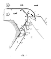
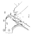
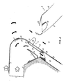
- FIGs. 1, 2 and 3 a typical operating sequence is shown for an embodiment of the cooling air diverter.
- cooling air is shown entering the cooling air duct 1.
- the reverser vane system is isolated by the isolation valve 9 from the hot exhaust gas stream 16. Consequently, cooling air is diverted into the isolation valve cooling passage 15 to prevent thermal fatigue and extend its useful life.
- the outward seal end 14 With the isolation valve in the blocking position, the outward seal end 14 is sealingly engaged with the shoulder 4.
- the guide nose 12 engages the outer flap 23, allowing cooling air to be admitted to the passage 15.
- the outward seal end 14 engages the shoulder 4 to prevent exhaust gas from entering the cooling passage 15.
- the cam wall 11 simultaneously engages the lug 26 to drive the inner flap 22 into sealing engagement with the static seal 6, blocking the cooling flow from entering the conduit 10. Cooling air is thereby directed by the diverter 8 through the cooling passage 15, with the conduit 10 positively sealed.
- the diverter is shown in an intermediate stage of thrust transition.
- the isolation valve 9 begins to withdraw, retracting the guide nose 12.
- the outer flap 23 then correspondingly approaches the shoulder 4, reducing cooling flow to passage 15.
- lug 26, still engaged by the cam wall 11, prevents the disengagement of the inner flap 22 from the inner static seal 6.
- the floating flap 24 pivots about the hinge 25 and seals the gap between the inner and outer flaps, slidably engaging the outer flap 23, and thereby preventing cooling air from escaping through the lug access hole 27.
- a portion of the cooling air is allowed to escape into the exhaust gas stream during the transition period.
- the nozzle is shown in the reverse thrust configuration.
- the outer flap 23 mates with the shoulder 4, blocking airflow therethrough.
- the lug 26 disengages from the cam wall 11, allowing the inner flap 22 to disengage from the inner static seal 6, while the floating flap 24 seats against the outer flap 23. Cooling air is thereby diverted through the conduit 10. It should be noted that the cooling air provides sufficient pressure loading of the inner, outer and floating flaps to prevent valve flutter or gas leakage and that during the reciprocal transition from reverse to forward thrust operation, the above-described sequence is reversed, with the diverter selectively redirecting the flow of cooling air from the conduit 10 to the isolation valve cooling passage 15.
- the diverter disclosed herein provides simple and reliable cooling air directional control, automatically responding to changes in nozzle configuration without requiring additional actuation devices. Optimum cooling efficiency is achieved without adding to nozzle weight or increasing nozzle complexity. While the diverter has been described in relation to a valve for selectively alternating cooling airflow between a conduit and an isolation valve, it will be understood by those skilled in the art that such a diverter could be located in other areas of an exhaust nozzle to selectively divert cooling air between occasionally heated members in response to nozzle configuration.
Landscapes
- Engineering & Computer Science (AREA)
- Chemical & Material Sciences (AREA)
- Combustion & Propulsion (AREA)
- Mechanical Engineering (AREA)
- General Engineering & Computer Science (AREA)
- Aviation & Aerospace Engineering (AREA)
- Exhaust Silencers (AREA)
- Supercharger (AREA)
- Multiple-Way Valves (AREA)
- Lift Valve (AREA)
- Control Of Turbines (AREA)
- Turbine Rotor Nozzle Sealing (AREA)
Claims (3)
Applications Claiming Priority (2)
| Application Number | Priority Date | Filing Date | Title |
|---|---|---|---|
| US07/045,343 US4742961A (en) | 1987-05-04 | 1987-05-04 | Exhaust gas nozzle including a cooling air diverter |
| US45343 | 2001-10-25 |
Publications (2)
| Publication Number | Publication Date |
|---|---|
| EP0290371A1 EP0290371A1 (de) | 1988-11-09 |
| EP0290371B1 true EP0290371B1 (de) | 1991-12-18 |
Family
ID=21937350
Family Applications (1)
| Application Number | Title | Priority Date | Filing Date |
|---|---|---|---|
| EP88630085A Expired - Lifetime EP0290371B1 (de) | 1987-05-04 | 1988-05-03 | Schubdüse mit Kühlluftweiche |
Country Status (6)
| Country | Link |
|---|---|
| US (1) | US4742961A (de) |
| EP (1) | EP0290371B1 (de) |
| JP (1) | JPS63285248A (de) |
| KR (1) | KR950003753B1 (de) |
| CN (1) | CN1013982B (de) |
| DE (1) | DE3866941D1 (de) |
Families Citing this family (14)
| Publication number | Priority date | Publication date | Assignee | Title |
|---|---|---|---|---|
| GB2224080B (en) * | 1988-10-22 | 1993-04-07 | Rolls Royce Plc | Fluid outlet duct |
| US4926633A (en) * | 1989-06-27 | 1990-05-22 | The United States Of America As Represented By The Secretary Of The Air Force | Coolant pressure regulating apparatus |
| JPH0711259B2 (ja) * | 1989-09-07 | 1995-02-08 | ゼネラル・エレクトリック・カンパニイ | 排気ノズルヒンジ |
| US5101624A (en) * | 1989-09-07 | 1992-04-07 | General Electric Company | Exhaust nozzle hinge |
| DE4012212A1 (de) * | 1990-04-14 | 1991-10-24 | Mtu Muenchen Gmbh | Duese fuer ein hyperschalltriebwerk |
| FR2768773B1 (fr) * | 1997-09-25 | 1999-11-05 | Hispano Suiza Sa | Inverseur de poussee de turboreacteur a coquilles internes |
| US6406692B1 (en) * | 1997-10-31 | 2002-06-18 | New Horizons Diagnostics Corp | Composition for treatment of an ocular bacterial infection |
| US8001775B2 (en) * | 2005-08-16 | 2011-08-23 | Daimler Trucks North America Llc | Vehicle exhaust dilution and dispersion device |
| US7604093B2 (en) * | 2006-11-01 | 2009-10-20 | Daimler Trucks North America Llc | Exhaust diffuser for vehicle |
| DE102011101342A1 (de) * | 2011-05-12 | 2012-11-15 | Rolls-Royce Deutschland Ltd & Co Kg | Fluggasturbinentriebwerk mit Ölkühler in der Triebwerksverkleidung |
| US9243508B2 (en) | 2012-03-20 | 2016-01-26 | General Electric Company | System and method for recirculating a hot gas flowing through a gas turbine |
| CN108252821B (zh) * | 2017-12-26 | 2020-04-07 | 中国航发四川燃气涡轮研究院 | 一种用于喷管调节板与机匣的组合金属弹性密封结构 |
| CN114135419B (zh) * | 2021-10-20 | 2022-12-20 | 中国航发四川燃气涡轮研究院 | 一种用于喷管机匣与调节板的双接触金属密封结构 |
| CN114151228B (zh) * | 2022-02-09 | 2022-04-22 | 中国航发四川燃气涡轮研究院 | 二元矢量喷管调节片离散式冷气分区的方法 |
Family Cites Families (10)
| Publication number | Priority date | Publication date | Assignee | Title |
|---|---|---|---|---|
| US3837411A (en) * | 1973-11-21 | 1974-09-24 | Gen Electric | Diverter valve for a gas turbine with an augmenter |
| US3979065A (en) * | 1974-10-31 | 1976-09-07 | United Technologies Corporation | Cooling liner for an exhaust nozzle |
| US3949550A (en) * | 1975-03-05 | 1976-04-13 | United Technologies Corporation | Engine exhaust flow diverter |
| US4074523A (en) * | 1976-12-08 | 1978-02-21 | The United States Of America As Represented By The Secretary Of The Air Force | Pressure actuated collapsible curtain liners for a gas turbine engine nozzle |
| US4098076A (en) * | 1976-12-16 | 1978-07-04 | United Technologies Corporation | Cooling air management system for a two-dimensional aircraft engine exhaust nozzle |
| US4081137A (en) * | 1977-01-05 | 1978-03-28 | The United States Of America As Represented By The Secretary Of The Air Force | Finned surface cooled nozzle |
| US4643356A (en) * | 1977-08-31 | 1987-02-17 | United Technologies Corporation | Cooling liner for convergent-divergent exhaust nozzle |
| US4544098A (en) * | 1982-12-27 | 1985-10-01 | United Technologies Corporation | Cooled exhaust nozzle flaps |
| US4575006A (en) * | 1983-06-13 | 1986-03-11 | United Technologies Corporation | Nozzle flap edge seal |
| FR2557925B1 (fr) * | 1984-01-05 | 1986-05-16 | Hurel Dubois Avions | Perfectionnement aux moteurs a reaction a double flux equipes d'un inverseur de poussee. |
-
1987
- 1987-05-04 US US07/045,343 patent/US4742961A/en not_active Expired - Lifetime
-
1988
- 1988-05-02 JP JP63109826A patent/JPS63285248A/ja active Pending
- 1988-05-03 DE DE8888630085T patent/DE3866941D1/de not_active Expired - Lifetime
- 1988-05-03 EP EP88630085A patent/EP0290371B1/de not_active Expired - Lifetime
- 1988-05-04 CN CN88102721A patent/CN1013982B/zh not_active Expired
- 1988-05-04 KR KR1019880005175A patent/KR950003753B1/ko not_active Expired - Fee Related
Also Published As
| Publication number | Publication date |
|---|---|
| KR950003753B1 (ko) | 1995-04-18 |
| KR880014243A (ko) | 1988-12-23 |
| CN1013982B (zh) | 1991-09-18 |
| CN88102721A (zh) | 1988-11-16 |
| EP0290371A1 (de) | 1988-11-09 |
| DE3866941D1 (de) | 1992-01-30 |
| US4742961A (en) | 1988-05-10 |
| JPS63285248A (ja) | 1988-11-22 |
Similar Documents
| Publication | Publication Date | Title |
|---|---|---|
| EP0290371B1 (de) | Schubdüse mit Kühlluftweiche | |
| US6647708B2 (en) | Multi-spool by-pass turbofan engine | |
| US4285194A (en) | Apparatus and method for controlling fan duct flow in a gas turbine engine | |
| US6910851B2 (en) | Turbofan jet engine having a turbine case cooling valve | |
| US5048288A (en) | Combined turbine stator cooling and turbine tip clearance control | |
| US5269135A (en) | Gas turbine engine fan cooled heat exchanger | |
| US7871242B2 (en) | Single actuator controlled rotational flow balance system | |
| CN102536513B (zh) | 操作用于涡轮风扇推进系统的推力反向器的系统和方法 | |
| US4447190A (en) | Fluid pressure control in a gas turbine engine | |
| US9670798B2 (en) | Turbojet engine nacelle with variable ventilation outlet cross section | |
| US4805401A (en) | Control vent for diverting exhaust nozzle | |
| GB1561138A (en) | Gas turbine engines | |
| EP1918560B1 (de) | Kombinierte Steuerung der Zufuhr von Kühlluft und Trägerluft in eine Turbinenmotordüse | |
| CA1065621A (en) | Cooling system for a thrust vectoring gas turbine engine exhaust system | |
| US4767055A (en) | Method and linkage for positioning a convergent flap and coaxial arc valve | |
| US4714197A (en) | 2-D propulsive lift nozzle | |
| JPH02286861A (ja) | ターボジェット・エンジン | |
| CA1279199C (en) | Variable area exhaust nozzle for a gas turbine engine | |
| US4073441A (en) | Gas turbine engine nozzle apparatus including a nozzle flap slot seal | |
| US20060101805A1 (en) | Floating flexible firewall seal | |
| CA2021086A1 (en) | Exhaust nozzle hinge | |
| CN119878373B (zh) | 一种组合发动机进气密封与环控一体化热管理系统及方法 | |
| US20250116338A1 (en) | Double bellows valve for preventing undesired valve failure positions | |
| GB2276434A (en) | Cam-operated valve | |
| GB2261917A (en) | Valve for diverting fluid flows in turbomachines |
Legal Events
| Date | Code | Title | Description |
|---|---|---|---|
| PUAI | Public reference made under article 153(3) epc to a published international application that has entered the european phase |
Free format text: ORIGINAL CODE: 0009012 |
|
| AK | Designated contracting states |
Kind code of ref document: A1 Designated state(s): DE FR GB IT |
|
| 17P | Request for examination filed |
Effective date: 19890328 |
|
| 17Q | First examination report despatched |
Effective date: 19891109 |
|
| GRAA | (expected) grant |
Free format text: ORIGINAL CODE: 0009210 |
|
| AK | Designated contracting states |
Kind code of ref document: B1 Designated state(s): DE FR GB IT |
|
| ET | Fr: translation filed | ||
| REF | Corresponds to: |
Ref document number: 3866941 Country of ref document: DE Date of ref document: 19920130 |
|
| ITF | It: translation for a ep patent filed | ||
| PLBE | No opposition filed within time limit |
Free format text: ORIGINAL CODE: 0009261 |
|
| STAA | Information on the status of an ep patent application or granted ep patent |
Free format text: STATUS: NO OPPOSITION FILED WITHIN TIME LIMIT |
|
| 26N | No opposition filed | ||
| PGFP | Annual fee paid to national office [announced via postgrant information from national office to epo] |
Ref country code: FR Payment date: 19940413 Year of fee payment: 7 |
|
| PGFP | Annual fee paid to national office [announced via postgrant information from national office to epo] |
Ref country code: DE Payment date: 19940425 Year of fee payment: 7 |
|
| PG25 | Lapsed in a contracting state [announced via postgrant information from national office to epo] |
Ref country code: DE Effective date: 19960201 |
|
| PG25 | Lapsed in a contracting state [announced via postgrant information from national office to epo] |
Ref country code: FR Effective date: 19960229 |
|
| REG | Reference to a national code |
Ref country code: FR Ref legal event code: ST |
|
| REG | Reference to a national code |
Ref country code: FR Ref legal event code: ST |
|
| PGFP | Annual fee paid to national office [announced via postgrant information from national office to epo] |
Ref country code: GB Payment date: 19990420 Year of fee payment: 12 |
|
| PG25 | Lapsed in a contracting state [announced via postgrant information from national office to epo] |
Ref country code: GB Free format text: LAPSE BECAUSE OF NON-PAYMENT OF DUE FEES Effective date: 20000503 |
|
| GBPC | Gb: european patent ceased through non-payment of renewal fee |
Effective date: 20000503 |
|
| PG25 | Lapsed in a contracting state [announced via postgrant information from national office to epo] |
Ref country code: IT Free format text: LAPSE BECAUSE OF NON-PAYMENT OF DUE FEES;WARNING: LAPSES OF ITALIAN PATENTS WITH EFFECTIVE DATE BEFORE 2007 MAY HAVE OCCURRED AT ANY TIME BEFORE 2007. THE CORRECT EFFECTIVE DATE MAY BE DIFFERENT FROM THE ONE RECORDED. Effective date: 20050503 |