EP0290082B1 - Compact steel cord structure - Google Patents
Compact steel cord structure Download PDFInfo
- Publication number
- EP0290082B1 EP0290082B1 EP88200808A EP88200808A EP0290082B1 EP 0290082 B1 EP0290082 B1 EP 0290082B1 EP 88200808 A EP88200808 A EP 88200808A EP 88200808 A EP88200808 A EP 88200808A EP 0290082 B1 EP0290082 B1 EP 0290082B1
- Authority
- EP
- European Patent Office
- Prior art keywords
- steel
- filaments
- steel cord
- cord
- diameter
- Prior art date
- Legal status (The legal status is an assumption and is not a legal conclusion. Google has not performed a legal analysis and makes no representation as to the accuracy of the status listed.)
- Expired - Lifetime
Links
Images


Classifications
-
- D—TEXTILES; PAPER
- D07—ROPES; CABLES OTHER THAN ELECTRIC
- D07B—ROPES OR CABLES IN GENERAL
- D07B1/00—Constructional features of ropes or cables
- D07B1/06—Ropes or cables built-up from metal wires, e.g. of section wires around a hemp core
-
- D—TEXTILES; PAPER
- D07—ROPES; CABLES OTHER THAN ELECTRIC
- D07B—ROPES OR CABLES IN GENERAL
- D07B1/00—Constructional features of ropes or cables
- D07B1/06—Ropes or cables built-up from metal wires, e.g. of section wires around a hemp core
- D07B1/0606—Reinforcing cords for rubber or plastic articles
- D07B1/062—Reinforcing cords for rubber or plastic articles the reinforcing cords being characterised by the strand configuration
- D07B1/0626—Reinforcing cords for rubber or plastic articles the reinforcing cords being characterised by the strand configuration the reinforcing cords consisting of three core wires or filaments and at least one layer of outer wires or filaments, i.e. a 3+N configuration
-
- D—TEXTILES; PAPER
- D07—ROPES; CABLES OTHER THAN ELECTRIC
- D07B—ROPES OR CABLES IN GENERAL
- D07B2201/00—Ropes or cables
- D07B2201/20—Rope or cable components
- D07B2201/2015—Strands
- D07B2201/2036—Strands characterised by the use of different wires or filaments
- D07B2201/2037—Strands characterised by the use of different wires or filaments regarding the dimension of the wires or filaments
-
- D—TEXTILES; PAPER
- D07—ROPES; CABLES OTHER THAN ELECTRIC
- D07B—ROPES OR CABLES IN GENERAL
- D07B2207/00—Rope or cable making machines
- D07B2207/20—Type of machine
- D07B2207/204—Double twist winding
- D07B2207/205—Double twist winding comprising flyer
-
- Y—GENERAL TAGGING OF NEW TECHNOLOGICAL DEVELOPMENTS; GENERAL TAGGING OF CROSS-SECTIONAL TECHNOLOGIES SPANNING OVER SEVERAL SECTIONS OF THE IPC; TECHNICAL SUBJECTS COVERED BY FORMER USPC CROSS-REFERENCE ART COLLECTIONS [XRACs] AND DIGESTS
- Y10—TECHNICAL SUBJECTS COVERED BY FORMER USPC
- Y10S—TECHNICAL SUBJECTS COVERED BY FORMER USPC CROSS-REFERENCE ART COLLECTIONS [XRACs] AND DIGESTS
- Y10S57/00—Textiles: spinning, twisting, and twining
- Y10S57/902—Reinforcing or tyre cords
Definitions
- the invention relates to a steel cord adapted for the reinforcement of rubber articles such as rubber tyres.
- a steel cord adapted for the reinforcement of rubber articles conveniently comprises steel filaments having a carbon content of more than 0.60 per cent by weight (e.g. more than 0.65%, 0.78%, 0.82% or 0.95%).
- a typical steel composition is: a minimum carbon content above 0.65%, a manganese content between 0.40% and 0.70%, a silicon content between 0.15% and 0.30% and a maximum sulphur and maximum phosphorus content of 0.03%, all percentages being percentages by weight.
- Other, more expensive, elements such as chromium may also be alloyed.
- the diameter of such adapted steel filament lies in the range of 0.05 mm to 0.80 mm, preferably in the range of 0.05 mm to 0.40 mm (e.g. 0.08 mm, 0.16 mm or 0.31 mm).
- the elongation at rupture of a steel filament adapted for the reinforcement of rubber articles is at lest 1%, preferably at least 2.5%.
- the steel filaments are usually provided with a coating which promotes the adherence of the steel wire to rubber articles.
- a coating conveniently comprises copper, zinc, brass or ternary brass alloy, or a combination of two or more different layers thereof.
- the thickness of the coating ranges from 0.05 to 0.40 micron, preferably from 0.12 to 0.22 micron.
- the coating can also be present in the form of a thin film of chemical primer material for ensuring good rubber penetration and adhesion.
- a compact steel cord is a steel cord, all the composing steel filaments of which have the same twist direction and twist pitch and have contacts with adjacent steel filaments.
- Compact steel cords present in comparison with other cord structures several advantages: a compact steel cord can be manufactured within one single process step as can be derived from patent specification US-A-4.332.131.
- a second advantage is that the composing steel filaments have line contacts with each other.
- compact steel cords have also many drawbacks. They have core migration and the breaking load per cord cross-section is rather low. The breaking load per cord cross-section is defined as the load necessary to break the cord divided by the surface of the circumscribed circle.
- the layer around the core comprises at least one filament having a diameter which is less than the diameter of the core filaments.
- the breaking load per cross-section is still rather low.
- the invention discloses a device according to EP-A-0 194 011 wherein is provided a steel cord adapted for the reinforcement of rubber articles, said steel cord comprising a central bundle of these twisted steel filaments of a diameter d1 and nine steel filaments twisted around said central bundle with the same twist pitch and twist direction as said central bundle, a first group of three steel filaments of said nine steel filaments having a diameter d2 and contacting the two adjacent steel filaments of the central bundle, a second group of six steel filaments of said wire steel filaments having a diameter of d3 and contacting both one steel filament of the central bundle and one steel filament of said first group, characterized in that the ratio d2/d1 is greater than 1.05 and smaller than 1.16 and in that the ratio d3/d1 is greater than _ 0.205 + 0.814 ⁇ d2/d1 and smaller than _ 0.105 + 50.814 ⁇ d2/d1.
- a central bundle of three filaments having a diameter d1 means that the deviation of the diameter of each of the three filaments is not greater than three per cent of the mean value of the diameter d1.
- the mean values of the diameters d1, d2, d3 are used for the ratios d2/d1 and d3/d1.
- the ratio d2/d1 must be smaller than 1.16 in order to avoid core migration, and must be greater than 1.05 in order to have a high value of the breaking load per cross-section.
- the ratio d3/d1 must be greater than _ 0.205 + 0.814 ⁇ d2/d1 and smaller than _ 0.105 + 0.814 ⁇ d2/d1 in order to have a cross-section that has a sufficient roundness as defined herein below.
- the steel cord according to the invention may or may not be wrapped around by a single steel filament.
- This single steel filament may have a diameter different from the diameters d1, d2 and d3.
- the wrapping direction or the wrapping pitch or both are different from resp. the twisting direction and the twisting pitch of the other steel filaments.
- the wrapping pitch is preferably smaller than the twisting pitch of the other steel filaments.
- the invention also relates to a rubber product reinforced with a steel cord as defined herein above.
- This rubber product may be a tyre.
- the steel cord according to the invention is then located in a belt or carcass ply of the tyre.
- three twisted steel filaments 1, having a diameter d1 are forming the central bundle of a steel cord according to the invention.
- Three steel filaments 2 have a diameter d2 and contact two adjacent steel filaments 1 of the central bundle.
- Six steel filaments 3 have a diameter d3 and contact both one steel filament 1 of the central bundle and one steel filament 2.
- the steel cord structure according to the invention shows an openness for the steel filaments 2 and 3.
- the following ratio must be greater than 0.10, preferably greater than 0.15.
- Distances 4-5-6 are measured along a circle with the same centre as the cross-section of the steel cord structure and going through the centre of the cross-section of steel filaments 3.
- 2 d3 is an approximation of the distances along this circle corresponding with the cross-section of the steel filaments 3. If the ratio d2/d1 is greater than 1.16 than it is impossible to obtain a steel cord structure that has a sufficient rubber penetration and is sufficiently round.
- the steel cord structure according to the invention is round. This means that the distance 7 from the centre of the cross-section of the steel cord to the most remote point of the cross-section of steel filament 3 is about equal to the distance 8 from the centre of the cross-section of the steel cord to the most remote point of the cross-section of steel filament 2.
- a steel cord is defined as having a sufficient roundness if 0.97 ⁇ distance 7 distance 8 ⁇ 1.03 this corresponds to _ 0.205 + 0.814 ⁇ d2/d1 ⁇ d3/d1 ⁇ _ 0.105 + 0.814 ⁇ d2/d1
- the dots in figure 1 correspond to contacts between the different steel filaments. These contacts are line contacts along the length of the steel cord. However, these contacts are not necessarily contacts "steel-to-steel". It is possible that between some adjacent steel filaments there is a small sheath of rubber.
- Figure 2 shows another example of a cross-section of a steel cord according to the invention:
- the twelve steel filaments 1, 2 and 3 are twisted in the S-direction with a twist pitch of 12.5 mm.
- a steel filament 9 with a diameter d4 of 0.08 mm is wrapped around the steel cord in the Z-direction with a pitch of 6.5 mm.
- the steel cord can be made by a process using a conventional double-twister 10 as shown in figure 3.
- the twelve wires are unwound from a creel (not shown), pass through a guiding plate 11 and converge towards a twisting-die 12 into a bundle. Then the bundle enters axially through the rotation axis 13 of the twister, over the rotating flyer 14 back to the rotation axis on the other side, where it enters axially into the stationary cradle 15 inside the twister over capstan 16 for winding up on the bobbin 17.
- the capstan 16 draws the bundle from the unwinding creel through the machine.
- a wrapping steel filament 9 is to be provided, this can be done by a conventional wrapping machine 19 situated between pulley 18 and capstan 16.
- a cross-section of the guiding plate 11 along the line IV-IV is shown in figure 4. Holes 111, 112 and 113 guide resp. filaments 1, 2 and 3.
- the rubber products comprising a steel cord according to the invention are then obtained by introducing such wires in an unvulcanized rubber composition and then vulcanizing the whole.
- the steel cord is firstly impregnated in an adhesion rubber composition.
- adhesion rubber will conveniently comprise 40 and 70 part of carbon black per 100 parts of rubber, 2 to 6 parts of coumarone resin, 4 to 12 parts of zinc oxide and 1 to 5 of sulphur, and further not more than 10 parts in total of antioxidant or accelerator or other agents, all parts being parts by weight.
- steel cords according to the invention are used in the belt or carcass ply of a tyre, they are laid side by side to form a foil of one or more superposed layers of cords and this foil is covered on either side with a foil of unvulcanized adhesion rubber which enters between and into the cords. The whole is cut into strips and the result is a strip of cord pieces, lying side by side in one or more superposed layers, and impregnated wit unvulcanized adhesion rubber.
- the filling degree is the percentage of the surface of the circumscribed circle which is occupied by the cross-sections of the steel filaments. As can be derived from table 1 the breaking load per cross-section is 7 per cent above the breaking load per cross-section of a conventional steel cord. This is due to an optimal filling with steel.
- a Hunter test has been developed by the Hunter Spring Company, Lansdale, Pennsylvania. See U.S. patent 2.435.772 and F.A. Volta, New wire fatigue testing method, Iron Age, August 26, 1948. This Hunter test has been carried out n order to examine the behaviour of a steel cord according to the invention once embedded in rubber.
- the twisting pitch was for all samples equal to 12.5 mm.
- the bending stress is 400 N/mm2 bare cord, the duration of the test is 3800 minutes and the rotation direction of the cord is open.
- Table 2 summarizes the results as to fatigue limit and core migration.
- a steel cord according to the invention avoids core migration without loss of fatigue resistance.
Landscapes
- Ropes Or Cables (AREA)
- Tires In General (AREA)
Description
- The invention relates to a steel cord adapted for the reinforcement of rubber articles such as rubber tyres.
- A steel cord adapted for the reinforcement of rubber articles conveniently comprises steel filaments having a carbon content of more than 0.60 per cent by weight (e.g. more than 0.65%, 0.78%, 0.82% or 0.95%). A typical steel composition is: a minimum carbon content above 0.65%, a manganese content between 0.40% and 0.70%, a silicon content between 0.15% and 0.30% and a maximum sulphur and maximum phosphorus content of 0.03%, all percentages being percentages by weight. Other, more expensive, elements such as chromium may also be alloyed.
- The diameter of such adapted steel filament lies in the range of 0.05 mm to 0.80 mm, preferably in the range of 0.05 mm to 0.40 mm (e.g. 0.08 mm, 0.16 mm or 0.31 mm).
- The elongation at rupture of a steel filament adapted for the reinforcement of rubber articles is at
lest 1%, preferably at least 2.5%. - The steel filaments are usually provided with a coating which promotes the adherence of the steel wire to rubber articles. Such a coating conveniently comprises copper, zinc, brass or ternary brass alloy, or a combination of two or more different layers thereof. The thickness of the coating ranges from 0.05 to 0.40 micron, preferably from 0.12 to 0.22 micron. The coating can also be present in the form of a thin film of chemical primer material for ensuring good rubber penetration and adhesion.
- In this respect compact steel cords have been developed for the reinforcement of rubber articles. A compact steel cord is a steel cord, all the composing steel filaments of which have the same twist direction and twist pitch and have contacts with adjacent steel filaments. Compact steel cords present in comparison with other cord structures several advantages: a compact steel cord can be manufactured within one single process step as can be derived from patent specification US-A-4.332.131. A second advantage is that the composing steel filaments have line contacts with each other. However, compact steel cords have also many drawbacks. They have core migration and the breaking load per cord cross-section is rather low. The breaking load per cord cross-section is defined as the load necessary to break the cord divided by the surface of the circumscribed circle. Low values of the breaking load per cross-section bring about large cord diameters and consequently thick rubber plies and a small number of steel cords per rubber ply. Still another drawback of compact cords is a low fatigue limit especially caused by fretting wear between filaments of the same layer.
- According to the prior art there have been several attempts to avoid the phenomenon of core migration. In patent application EP-A-0169.588 (a) there has been shown a steel cord twisting structure where wire migration is reduced by changing the relative position of the steel filaments of the central bundle. In patent application EP-A-0168.858 (b) there has been shown a steel cord where the diameter and twist pith of the core wires is substantially different from the diameter and twist pitch of the filaments of the layer. In these applications (a) and (b) the problem of core migration is solved. However, the steel cord structures according to these applications (a) and (b) depart from the compact cord structure as defined herein, i.e. a cord the filaments of which have the same twist direction and twist pitch and showing nothing but line contacts between each other.
- A compact steel cord structure which tackles the problem of fretting wear is disclosed in patent application EP 0194011 : the layer around the core comprises at least one filament having a diameter which is less than the diameter of the core filaments. However, the breaking load per cross-section is still rather low.
- The invention discloses a device according to EP-A-0 194 011 wherein is provided a steel cord adapted for the reinforcement of rubber articles, said steel cord comprising a central bundle of these twisted steel filaments of a diameter d₁ and nine steel filaments twisted around said central bundle with the same twist pitch and twist direction as said central bundle, a first group of three steel filaments of said nine steel filaments having a diameter d₂ and contacting the two adjacent steel filaments of the central bundle, a second group of six steel filaments of said wire steel filaments having a diameter of d₃ and contacting both one steel filament of the central bundle and one steel filament of said first group,
characterized in that
the ratio d₂/d₁ is greater than 1.05 and smaller than 1.16 and in that the ratio d₃/d₁ is greater than _ 0.205 + 0.814 × d₂/d₁ and smaller than _ 0.105 + 50.814 × d₂/d₁. - A central bundle of three filaments having a diameter d₁ means that the deviation of the diameter of each of the three filaments is not greater than three per cent of the mean value of the diameter d₁. The same applies _ mutatis mutandis _ for the first group of three filaments having a diameter d₂ and for the second group of six filaments having a diameter d₃.
- The mean values of the diameters d₁, d₂, d₃ are used for the ratios d₂/d₁ and d₃/d₁.
- The ratio d₂/d₁ must be smaller than 1.16 in order to avoid core migration, and must be greater than 1.05 in order to have a high value of the breaking load per cross-section.
- The ratio d₃/d₁ must be greater than _ 0.205 + 0.814 × d₂/d₁ and smaller than _ 0.105 + 0.814 × d₂/d₁ in order to have a cross-section that has a sufficient roundness as defined herein below.
- The steel cord according to the invention may or may not be wrapped around by a single steel filament. This single steel filament may have a diameter different from the diameters d₁, d₂ and d₃. The wrapping direction or the wrapping pitch or both are different from resp. the twisting direction and the twisting pitch of the other steel filaments. The wrapping pitch is preferably smaller than the twisting pitch of the other steel filaments.
- The invention also relates to a rubber product reinforced with a steel cord as defined herein above. This rubber product may be a tyre. The steel cord according to the invention is then located in a belt or carcass ply of the tyre.
- The invention will now be described in more detail with reference to the accompanying drawings wherein:
- Figure 1 represents a first example of a cross-section of a steel cord according to the invention.
- Figure 2 represents a second example of a cross-section of a steel cord according to the invention.
- Figure 3 represents a double-twister adapted to manufacture the steel cord according to the invention.
- Figure 4 represents a guiding plate of the double-twister.
- Referring to figure 1 three
twisted steel filaments 1, having a diameter d₁, are forming the central bundle of a steel cord according to the invention. Nine steel filaments, designated by 2 and 3, are twisted around the central bundle in the same twist direction and with the same twist pitch as the central bundle. - Three
steel filaments 2 have a diameter d₂ and contact twoadjacent steel filaments 1 of the central bundle. - Six
steel filaments 3 have a diameter d₃ and contact both onesteel filament 1 of the central bundle and onesteel filament 2. - The steel cord structure according to the invention shows an openness for the
steel filaments 
steel filaments 3. 2 d₃ is an approximation of the distances along this circle corresponding with the cross-section of thesteel filaments 3. If the ratio d₂/d₁ is greater than 1.16 than it is impossible to obtain a steel cord structure that has a sufficient rubber penetration and is sufficiently round. - The steel cord structure according to the invention is round. This means that the distance 7 from the centre of the cross-section of the steel cord to the most remote point of the cross-section of
steel filament 3 is about equal to the distance 8 from the centre of the cross-section of the steel cord to the most remote point of the cross-section ofsteel filament 2. - A steel cord is defined as having a sufficient roundness if

this corresponds to

- The dots in figure 1 correspond to contacts between the different steel filaments. These contacts are line contacts along the length of the steel cord. However, these contacts are not necessarily contacts "steel-to-steel". It is possible that between some adjacent steel filaments there is a small sheath of rubber.
- Figure 2 shows another example of a cross-section of a steel cord according to the invention:
- diameter d₁ of
steel filaments 1 is equal to 0.28 mm - diameter d₂ of
steel filaments 2 is equal to 0.30 mm - diameter d₃ of
steel filaments 3 is equal to 0.20 mm. - The twelve
steel filaments - The steel cord can be made by a process using a conventional double-
twister 10 as shown in figure 3. The twelve wires are unwound from a creel (not shown), pass through a guidingplate 11 and converge towards a twisting-die 12 into a bundle. Then the bundle enters axially through therotation axis 13 of the twister, over the rotatingflyer 14 back to the rotation axis on the other side, where it enters axially into thestationary cradle 15 inside the twister overcapstan 16 for winding up on thebobbin 17. Thecapstan 16 draws the bundle from the unwinding creel through the machine. - If a wrapping steel filament 9 is to be provided, this can be done by a
conventional wrapping machine 19 situated betweenpulley 18 andcapstan 16. - A cross-section of the guiding
plate 11 along the line IV-IV is shown in figure 4.Holes filaments - The rubber products comprising a steel cord according to the invention are then obtained by introducing such wires in an unvulcanized rubber composition and then vulcanizing the whole. In general, the steel cord is firstly impregnated in an adhesion rubber composition. Such adhesion rubber will conveniently comprise 40 and 70 part of carbon black per 100 parts of rubber, 2 to 6 parts of coumarone resin, 4 to 12 parts of zinc oxide and 1 to 5 of sulphur, and further not more than 10 parts in total of antioxidant or accelerator or other agents, all parts being parts by weight.
- If steel cords according to the invention are used in the belt or carcass ply of a tyre, they are laid side by side to form a foil of one or more superposed layers of cords and this foil is covered on either side with a foil of unvulcanized adhesion rubber which enters between and into the cords. The whole is cut into strips and the result is a strip of cord pieces, lying side by side in one or more superposed layers, and impregnated wit unvulcanized adhesion rubber.
- In order to show the high breaking load per cross-section of a steel cord according to the invention, 4 examples of the steel cord according to the invention are compared with a conventional compact steel cord. The twisting pitch was for all samples equal to 12.5 mm. The results are summarized in table 1.

- The filling degree is the percentage of the surface of the circumscribed circle which is occupied by the cross-sections of the steel filaments. As can be derived from table 1 the breaking load per cross-section is 7 per cent above the breaking load per cross-section of a conventional steel cord. This is due to an optimal filling with steel.
- A Hunter test has been developed by the Hunter Spring Company, Lansdale, Pennsylvania. See U.S. patent 2.435.772 and F.A. Volta, New wire fatigue testing method, Iron Age, August 26, 1948. This Hunter test has been carried out n order to examine the behaviour of a steel cord according to the invention once embedded in rubber. A steel cord according to the invention is compared with a conventional compact steel cord and with another compact steel cord (cc = compact cord). The twisting pitch was for all samples equal to 12.5 mm. The bending stress is 400 N/mm² bare cord, the duration of the test is 3800 minutes and the rotation direction of the cord is open.
- Table 2 summarizes the results as to fatigue limit and core migration.
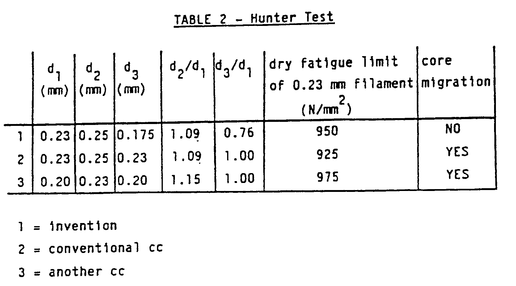
- As can be derived from table 2 a steel cord according to the invention avoids core migration without loss of fatigue resistance.
Claims (4)
a first group of three steel filaments (2) of said nine steel filaments having a diameter d₂ and contacting two adjacent steel filaments of the central bundle,
a second group of six steel filaments (3) of said nine steel filaments having a diameter d₃ and contacting both one steel filament of the central bundle and one steel filament of said first group,
characterized in that
the ratio d₂/d₁ is greater than 1.05 and smaller than 1.16 and in that the ratio d₃/d₁ is greater than _ 0.205 + 0.814 × d₂/d₁ and smaller than _ 0.105 + 0.814 × d₂/d₁.
Priority Applications (1)
| Application Number | Priority Date | Filing Date | Title |
|---|---|---|---|
| AT88200808T ATE62944T1 (en) | 1987-05-04 | 1988-04-26 | COMPACT STEEL CABLE STRUCTURE. |
Applications Claiming Priority (2)
| Application Number | Priority Date | Filing Date | Title |
|---|---|---|---|
| EP87200821 | 1987-05-04 | ||
| EP87200821 | 1987-05-04 |
Publications (2)
| Publication Number | Publication Date |
|---|---|
| EP0290082A1 EP0290082A1 (en) | 1988-11-09 |
| EP0290082B1 true EP0290082B1 (en) | 1991-04-24 |
Family
ID=8197612
Family Applications (1)
| Application Number | Title | Priority Date | Filing Date |
|---|---|---|---|
| EP88200808A Expired - Lifetime EP0290082B1 (en) | 1987-05-04 | 1988-04-26 | Compact steel cord structure |
Country Status (11)
| Country | Link |
|---|---|
| US (1) | US4829760A (en) |
| EP (1) | EP0290082B1 (en) |
| JP (1) | JPS6445884A (en) |
| KR (1) | KR950005438B1 (en) |
| AU (1) | AU592263B2 (en) |
| BR (1) | BR8802147A (en) |
| CA (1) | CA1281619C (en) |
| DE (1) | DE3862514D1 (en) |
| ES (1) | ES2022593B3 (en) |
| GR (1) | GR3002005T3 (en) |
| TR (1) | TR23758A (en) |
Families Citing this family (21)
| Publication number | Priority date | Publication date | Assignee | Title |
|---|---|---|---|---|
| ES2028252T3 (en) * | 1987-05-20 | 1992-07-01 | N.V. Bekaert S.A. | INTERMEDIATE STEEL WIRE COATING. |
| US4914902A (en) * | 1989-03-14 | 1990-04-10 | E. I. Du Pont De Nemours And Company | High strength cored cords |
| US4938016A (en) * | 1989-03-20 | 1990-07-03 | The Goodyear Tire & Rubber Company | Wire strand for elastomer reinforcement |
| JPH0811872B2 (en) * | 1990-11-29 | 1996-02-07 | 株式会社ブリヂストン | Steel cord and pneumatic radial tire for reinforcing rubber articles |
| KR940006811A (en) * | 1992-09-18 | 1994-04-25 | 카알 에이취. 크루코우 | Radial tires with monofilaments of steel on carcass ply |
| AU674070B2 (en) * | 1993-07-20 | 1996-12-05 | N.V. Bekaert S.A. | Steel cord construction |
| EP1314813A1 (en) * | 2001-11-23 | 2003-05-28 | N.V. Bekaert S.A. | Cable and window elevator system using such cable |
| US6763875B2 (en) * | 2002-02-06 | 2004-07-20 | Andersen Corporation | Reduced visibility insect screen |
| US20050098277A1 (en) * | 2002-02-06 | 2005-05-12 | Alex Bredemus | Reduced visibility insect screen |
| CN100365195C (en) * | 2003-02-27 | 2008-01-30 | 贝卡尔特股份有限公司 | lift rope |
| KR100544460B1 (en) | 2003-11-21 | 2006-01-24 | 삼성전자주식회사 | Volume control method and volume control function of external audio playback device by volume control key of remote control device |
| US20080040980A1 (en) * | 2006-07-13 | 2008-02-21 | Unimin Corporation | Method of processing nepheline syenite |
| CN103298996B8 (en) * | 2011-01-10 | 2019-12-03 | 贝卡尔特公司 | compact steel cord |
| JP5582612B2 (en) * | 2011-03-03 | 2014-09-03 | 朝日インテック株式会社 | Body recovery mechanism rope |
| CN104040070B (en) * | 2012-01-18 | 2016-09-21 | 贝卡尔特公司 | The steel cord of full elastomer penetration |
| PL3645785T3 (en) | 2017-06-27 | 2024-11-04 | Bekaert Advanced Cords Aalter Nv | A reinforcement strand for reinforcing a polymer article |
| EP3645442B1 (en) | 2017-06-27 | 2024-05-22 | Bekaert Advanced Cords Aalter NV | Belt reinforced with steel strands |
| FI3701083T3 (en) | 2017-10-27 | 2023-03-20 | Bekaert Advanced Cords Aalter Nv | Steel cord for elastomer reinforcement |
| JP7500554B2 (en) | 2018-10-23 | 2024-06-17 | ベカルト アドバンスド コーズ アールテル エンベー | Steel wire ropes, coated steel wire ropes and belts containing steel wire ropes |
| US12684391B2 (en) | 2021-03-18 | 2026-07-14 | Telefonaktiebolaget Lm Ericsson (Publ) | Mobility measurement reporting for XR services |
| WO2025168369A1 (en) | 2024-02-09 | 2025-08-14 | Bekaert Advanced Cords Aalter Nv | Steel strand and belt reinforced with said steel strand |
Family Cites Families (9)
| Publication number | Priority date | Publication date | Assignee | Title |
|---|---|---|---|---|
| US2435772A (en) * | 1944-08-16 | 1948-02-10 | Hunter Pressed Steel Company | Method and apparatus for testing wire |
| BE655593A (en) * | 1964-11-12 | 1965-03-01 | ||
| DE1803316B2 (en) * | 1968-10-16 | 1972-02-17 | TWO-LAYER STRAND OR TWO-LAYER ROPE | |
| DE2157204C2 (en) * | 1971-11-18 | 1983-10-20 | Gustav Wolf Seil- und Drahtwerke GmbH & Co, 4830 Gütersloh | Two-layer wire reinforcement of parallel lay - has one wire in three of outer layer with smaller dia. |
| FR2433989A1 (en) * | 1978-08-22 | 1980-03-21 | Sodetal | METAL CABLE AND MANUFACTURING METHOD |
| JPS58188201U (en) * | 1982-06-04 | 1983-12-14 | 株式会社ブリヂストン | radial tires |
| JPS59124404A (en) * | 1982-12-29 | 1984-07-18 | Bridgestone Corp | Pneumatic radial tire |
| EP0168858B1 (en) * | 1984-07-09 | 1989-05-31 | N.V. Bekaert S.A. | Compact steel cord for improved tensile strength |
| AU563184B2 (en) * | 1985-02-26 | 1987-07-02 | Bridgestone Corporation | Steel reinforcement cords |
-
1988
- 1988-04-22 US US07/184,684 patent/US4829760A/en not_active Expired - Lifetime
- 1988-04-26 EP EP88200808A patent/EP0290082B1/en not_active Expired - Lifetime
- 1988-04-26 ES ES88200808T patent/ES2022593B3/en not_active Expired - Lifetime
- 1988-04-26 CA CA000565141A patent/CA1281619C/en not_active Expired - Fee Related
- 1988-04-26 DE DE8888200808T patent/DE3862514D1/en not_active Expired - Lifetime
- 1988-04-28 JP JP63107387A patent/JPS6445884A/en active Pending
- 1988-05-03 BR BR8802147A patent/BR8802147A/en not_active IP Right Cessation
- 1988-05-03 AU AU15526/88A patent/AU592263B2/en not_active Ceased
- 1988-05-04 TR TR88/0332A patent/TR23758A/en unknown
- 1988-05-04 KR KR1019880005200A patent/KR950005438B1/en not_active Expired - Fee Related
-
1991
- 1991-05-28 GR GR91400557T patent/GR3002005T3/en unknown
Also Published As
| Publication number | Publication date |
|---|---|
| BR8802147A (en) | 1988-12-06 |
| CA1281619C (en) | 1991-03-19 |
| ES2022593B3 (en) | 1991-12-01 |
| EP0290082A1 (en) | 1988-11-09 |
| TR23758A (en) | 1990-09-12 |
| US4829760A (en) | 1989-05-16 |
| JPS6445884A (en) | 1989-02-20 |
| AU1552688A (en) | 1988-11-10 |
| DE3862514D1 (en) | 1991-05-29 |
| KR950005438B1 (en) | 1995-05-24 |
| GR3002005T3 (en) | 1992-12-30 |
| AU592263B2 (en) | 1990-01-04 |
| KR880014153A (en) | 1988-12-23 |
Similar Documents
| Publication | Publication Date | Title |
|---|---|---|
| US4829760A (en) | Compact steel cord structure | |
| US4627229A (en) | Compact steel cord for improved tensile strength | |
| EP1036235B1 (en) | Steel cord with waved elements | |
| US4836262A (en) | Metal cords and pneumatic tires using the same | |
| EP0373595A1 (en) | Steel cord fo reinforcing rubber | |
| EP0493410B1 (en) | Open cord structure | |
| US5285623A (en) | Steel cord with improved fatigue strength | |
| EP0382273B1 (en) | Compact cord | |
| EP1381730B1 (en) | Steel cord for reinforcing rubber articles | |
| WO1989009305A1 (en) | Open steel cord structure | |
| US5512380A (en) | Steel cord construction | |
| EP0675223A1 (en) | Layered steel cord construction | |
| EP0378534B1 (en) | High-tensile steel cord structure | |
| IE914457A1 (en) | Reinforced transmission belt | |
| US5743078A (en) | M+n steel cord with equal PLE per filament | |
| EP0635597A1 (en) | Steel cord construction | |
| EP0627520B1 (en) | Compact steel cord with no wrapping filament | |
| EP0661402A1 (en) | Steel cords for the reinforcement of rubber articles and method of producing the same | |
| JP3498274B2 (en) | Steel cord for reinforcing rubber products | |
| EP0466720B1 (en) | Steel cord with improved fatigue strength | |
| JPH07166484A (en) | Steel cord for reinforcing rubber articles and composite thereof | |
| JPS6351774B2 (en) |
Legal Events
| Date | Code | Title | Description |
|---|---|---|---|
| PUAI | Public reference made under article 153(3) epc to a published international application that has entered the european phase |
Free format text: ORIGINAL CODE: 0009012 |
|
| AK | Designated contracting states |
Kind code of ref document: A1 Designated state(s): AT BE CH DE ES FR GB GR IT LI LU NL SE |
|
| 17P | Request for examination filed |
Effective date: 19880426 |
|
| R17P | Request for examination filed (corrected) |
Effective date: 19890217 |
|
| 17Q | First examination report despatched |
Effective date: 19900927 |
|
| GRAA | (expected) grant |
Free format text: ORIGINAL CODE: 0009210 |
|
| AK | Designated contracting states |
Kind code of ref document: B1 Designated state(s): AT BE CH DE ES FR GB GR IT LI LU NL SE |
|
| PG25 | Lapsed in a contracting state [announced via postgrant information from national office to epo] |
Ref country code: NL Effective date: 19910424 Ref country code: SE Effective date: 19910424 Ref country code: AT Effective date: 19910424 Ref country code: CH Effective date: 19910424 Ref country code: LI Effective date: 19910424 |
|
| REF | Corresponds to: |
Ref document number: 62944 Country of ref document: AT Date of ref document: 19910515 Kind code of ref document: T |
|
| ITF | It: translation for a ep patent filed | ||
| REF | Corresponds to: |
Ref document number: 3862514 Country of ref document: DE Date of ref document: 19910529 |
|
| ET | Fr: translation filed | ||
| REG | Reference to a national code |
Ref country code: CH Ref legal event code: PL |
|
| NLV1 | Nl: lapsed or annulled due to failure to fulfill the requirements of art. 29p and 29m of the patents act | ||
| PLBI | Opposition filed |
Free format text: ORIGINAL CODE: 0009260 |
|
| 26 | Opposition filed |
Opponent name: GUSTAV WOLF SEIL- UND DRAHTWERKE GMBH & CO. Effective date: 19920120 |
|
| REG | Reference to a national code |
Ref country code: GR Ref legal event code: FG4A Free format text: 3002005 |
|
| PGFP | Annual fee paid to national office [announced via postgrant information from national office to epo] |
Ref country code: GR Payment date: 19940425 Year of fee payment: 7 |
|
| EPTA | Lu: last paid annual fee | ||
| PG25 | Lapsed in a contracting state [announced via postgrant information from national office to epo] |
Ref country code: GR Free format text: THE PATENT HAS BEEN ANNULLED BY A DECISION OF A NATIONAL AUTHORITY Effective date: 19951031 |
|
| REG | Reference to a national code |
Ref country code: GR Ref legal event code: MM2A Free format text: 3002005 |
|
| PLBN | Opposition rejected |
Free format text: ORIGINAL CODE: 0009273 |
|
| STAA | Information on the status of an ep patent application or granted ep patent |
Free format text: STATUS: OPPOSITION REJECTED |
|
| 27O | Opposition rejected |
Effective date: 19951009 |
|
| PGFP | Annual fee paid to national office [announced via postgrant information from national office to epo] |
Ref country code: GB Payment date: 19970224 Year of fee payment: 10 |
|
| PGFP | Annual fee paid to national office [announced via postgrant information from national office to epo] |
Ref country code: LU Payment date: 19980325 Year of fee payment: 11 |
|
| PG25 | Lapsed in a contracting state [announced via postgrant information from national office to epo] |
Ref country code: GB Free format text: LAPSE BECAUSE OF NON-PAYMENT OF DUE FEES Effective date: 19980426 |
|
| GBPC | Gb: european patent ceased through non-payment of renewal fee |
Effective date: 19980426 |
|
| PG25 | Lapsed in a contracting state [announced via postgrant information from national office to epo] |
Ref country code: LU Free format text: LAPSE BECAUSE OF NON-PAYMENT OF DUE FEES Effective date: 19990426 |
|
| PGFP | Annual fee paid to national office [announced via postgrant information from national office to epo] |
Ref country code: BE Payment date: 20060309 Year of fee payment: 19 |
|
| PGFP | Annual fee paid to national office [announced via postgrant information from national office to epo] |
Ref country code: ES Payment date: 20070426 Year of fee payment: 20 |
|
| PGFP | Annual fee paid to national office [announced via postgrant information from national office to epo] |
Ref country code: DE Payment date: 20070531 Year of fee payment: 20 |
|
| BERE | Be: lapsed |
Owner name: S.A. *BEKAERT N.V. Effective date: 20070430 |
|
| PGFP | Annual fee paid to national office [announced via postgrant information from national office to epo] |
Ref country code: IT Payment date: 20070523 Year of fee payment: 20 |
|
| PG25 | Lapsed in a contracting state [announced via postgrant information from national office to epo] |
Ref country code: BE Free format text: LAPSE BECAUSE OF NON-PAYMENT OF DUE FEES Effective date: 20070430 |
|
| PGFP | Annual fee paid to national office [announced via postgrant information from national office to epo] |
Ref country code: FR Payment date: 20070417 Year of fee payment: 20 |
|
| REG | Reference to a national code |
Ref country code: ES Ref legal event code: FD2A Effective date: 20080428 |
|
| PG25 | Lapsed in a contracting state [announced via postgrant information from national office to epo] |
Ref country code: ES Free format text: LAPSE BECAUSE OF EXPIRATION OF PROTECTION Effective date: 20080428 |