EP0289732B1 - Wiederzusammenbaubares Kernbrennstoffbündel - Google Patents
Wiederzusammenbaubares Kernbrennstoffbündel Download PDFInfo
- Publication number
- EP0289732B1 EP0289732B1 EP88103287A EP88103287A EP0289732B1 EP 0289732 B1 EP0289732 B1 EP 0289732B1 EP 88103287 A EP88103287 A EP 88103287A EP 88103287 A EP88103287 A EP 88103287A EP 0289732 B1 EP0289732 B1 EP 0289732B1
- Authority
- EP
- European Patent Office
- Prior art keywords
- dimples
- socket
- inner socket
- locking tube
- diameter
- Prior art date
- Legal status (The legal status is an assumption and is not a legal conclusion. Google has not performed a legal analysis and makes no representation as to the accuracy of the status listed.)
- Expired - Lifetime
Links
Images


Classifications
-
- G—PHYSICS
- G21—NUCLEAR PHYSICS; NUCLEAR ENGINEERING
- G21C—NUCLEAR REACTORS
- G21C3/00—Reactor fuel elements and their assemblies; Selection of substances for use as reactor fuel elements
- G21C3/30—Assemblies of a number of fuel elements in the form of a rigid unit
- G21C3/32—Bundles of parallel pin-, rod-, or tube-shaped fuel elements
- G21C3/334—Assembling, maintenance or repair of the bundles
-
- Y—GENERAL TAGGING OF NEW TECHNOLOGICAL DEVELOPMENTS; GENERAL TAGGING OF CROSS-SECTIONAL TECHNOLOGIES SPANNING OVER SEVERAL SECTIONS OF THE IPC; TECHNICAL SUBJECTS COVERED BY FORMER USPC CROSS-REFERENCE ART COLLECTIONS [XRACs] AND DIGESTS
- Y02—TECHNOLOGIES OR APPLICATIONS FOR MITIGATION OR ADAPTATION AGAINST CLIMATE CHANGE
- Y02E—REDUCTION OF GREENHOUSE GAS [GHG] EMISSIONS, RELATED TO ENERGY GENERATION, TRANSMISSION OR DISTRIBUTION
- Y02E30/00—Energy generation of nuclear origin
- Y02E30/30—Nuclear fission reactors
Definitions
- the present invention relates generally to reconstitutable fuel assemblies for nuclear reactors and, more particularly, to an arrangement for releasably attaching the top nozzle of a reconstitutable nuclear fuel assembly to a guide thimble.
- the reactor core includes a large number of fuel assemblies each of which is composed of top and bottom nozzles, with a plurality of elongate transversely spaced guide thimbles extending longitudinally between the nozzles, and a plurality of transverse support grids axially spaced along and attached to the guide thimbles.
- Each fuel assembly includes further a plurality of elongate fuel rods transversely spaced apart from one another and from the guide thimbles, and supported by the transverse grids between the top and bottom nozzles.
- the fuel rods, each of which contains fissile material are grouped together in an array organized to provide a neutron flux in the core sufficient to support a high rate of nuclear fission.
- the reactor has control rods which can be inserted into the guide thimbles to control the fission reaction which releases a large amount of energy in the form of heat.
- a liquid coolant is pumped upwardly through the core in order to extract some of the heat generated in the core for the production of useful work.
- the fuel rods may occasionally develop cracks along their lengths due primarily to internal stresses. These defective fuel rods must be replaced in the fuel assemblies, and this replacement must occur under water since the fuel assemblies become highly radioactive during their use in the reactor. To gain access to a defective fuel rod, it is necessary to remove the top and/or bottom nozzle of the fuel assembly.
- Reconstitutable fuel assemblies exist which are designed with removable nozzles. Typically, such removable nozzles have been either threadedly connected to the guide thimbles or attached thereto by means of bulge/groove arrangements employing locking tubes, such as disclosed in U.S. Patent US-A-4,631,168.
- the invention accordingly resides in an arrangement for releasably affixing the top nozzle of a reconstitutable nuclear fuel assembly to an upper end portion of a guide thimble, said arrangement comprising (a) a tubular inner socket defined by said upper end portion of the guide thimble, said inner socket having an upper rim portion with a peripheral bulge projecting radially outward therefrom and defining a substantially annular concavity on the inside of said rim portion, said tubular inner socket having formed therein elongate slots which extend longitudinally from the upper end thereof and through said upper rim portion, and which are angularly spaced apart; (b) an outer socket which extends through an adapter plate forming part of the top nozzle and has a smaller-diameter upper portion, a larger-diameter lower portion for slideably receiving part of the inner socket including said upper rim portion thereof, and a peripheral ledge formed between the upper and lower portions, said lower portion having an annular groove for receiving said peripheral bulge formed in
- the tip of said or each upper dimple is spaced from the longitudinal centerline of said tubular body a distance greater than half the diameter of said smaller-diameter upper portion of the outer socket; the tip of each of said lower dimples is spaced from the longitudinal centerline of said tubular body a distance greater than the difference between the wall thickness of said rim portion of the inner socket and half the diameter of the larger-diameter lower portion of the outer socket; and the spacing between the upper and lower dimples is less than the distance existing between said ledge and the lowermost edge of said concavity when said peripheral bulge is lodged in the annular groove of the outer socket.
- the locking tube has two upper dimples and four said lower dimples, the upper dimples preferably being disposed on the tubular body at locations substantially diametrically opposed to each other.
- the lower dimples preferably are arranged in two pairs, the lower dimples of each pair being disposed on said tubular body at locations substantially diametrically opposed to each other, and the two pairs of lower dimples being angularly spaced apart between ten and fourty-five, and preferably thirty, degrees.
- the upper dimples preferably also are substantially aligned, in the longitudinal direction of the locking tube, with the lower dimples of one of the two pairs.
- the fuel assembly 10 comprises a bottom nozzle 12 for supporting the assembly on the lower core plate (not shown) in the core region of a nuclear reactor, a plurality of guide thimbles 14 extending longitudinally upward from the bottom nozzle 12, a plurality of transverse grids 16 axially spaced along the guide thimbles 14, an organized array of elongate fuel rods 18 transversely spaced and supported by the grids 16, and a top nozzle 20 including an adapter plate 22 which is attached to upper end portions of the guide thimbles 14.
- the guide thimbles 14 are attached to the bottom nozzle 12.
- the top-nozzle-to-guide-thimble attachment arrangement embodying the invention comprises an outer socket 26 defined by a control-rod passageway extending through the adapter plate 22 of the top nozzle 20 of the reconstitutable fuel assembly 10; an inner socket 36 constituting an upper end portion of the respective guide thimble 14; and a locking tube 24.
- the outer socket 26 has a smaller-diameter upper portion 28, a larger-diameter lower portion 30 with an annular groove 34 formed circumferentially in the wall thereof, and a ledge 32 formed between the upper and lower portions 28, 30.
- the inner socket 36 is shown herein as a sleeve bulge-fit to the guide thimble 14 but it will be appreciated that, instead, it could be an integral upper end portion of the guide thimble itself.
- the inner socket 36 has an upper rim portion with a peripheral bulge 44 projecting radially outward therefrom, its inner surface 46 defining a substantially annular concavity 48 on the inside of the rim portion.
- the inner socket 36 also has formed therein a plurality (four, in the illustrated embodiment) of elongate slots 38 which extend longitudinally from the upper end 42 of the inner socket and through its rim portion including the peripheral bulge 44.
- the slots 38 are angularly spaced apart, the socket wall portions therebetween defining fingers 40.
- the bottom or lower-most edge of the concavity 48 is taken as the location farthest from the upper end 42 of the inner socket and where the inner diameter of the inner socket 36 first begins to increase to create the concavity 48.
- the preferably outwardly biased flexible fingers 40 on the inner socket 36 are resiliently compressed upon entering the lead-in chamfer 54 of the outer socket 26, and they elastically resume their normal or expanded positions when the bulge portions 44 thereon become aligned and mate with the annular groove 34 in the inner wall surface of the outer socket 26.
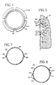
- the locking tube 24 as shown in Figures 6, 7 and 8, comprises a sleeve-like tubular body 56 with a flexible wall which has thereon at least one embossed upper dimple 58 with an apex or tip 60, and at least two angularly spaced embossed lower dimples 62 each with a tip 64.
- the top nozzle 20 is attached to the guide thimble 14, i.e. after insertion of each inner socket 36 into the associated outer socket 26, the locking tubes 24 are inserted coaxially into the respective inner sockets 36.
- the dimples 58 and 62 on the tubular body 56 of each locking tube 24 are arranged in a manner such that, when the locking tube 24 is in its proper locking position, as shown in Fig. 3 and particularly in Fig.
- the tip 60 of its upper dimple 58 is located at an elevation below and proximate the ledge 32 of the outer socket 26, and the tips 64 of its lower dimples 62 are located at an elevation above and proximate the elevation of the lowermost edge 52 of the concavity or recess 48 in the upper rim portion of the inner socket 36.
- the apex 60 of the upper dimple 58 being spaced from the longitudinal centerline of the tubular body 56 a distance greater than half the diameter of the upper portion 28 of the outer socket 26, projects radially into the larger-diameter lower portion 30 of the outer socket 26.
- This projection is made possible by creating a space, either by choosing dimensions, with respect to the rim/groove engagement, such that the upper end 42 of the inner socket is spaced away from the ledge 32 or by making the finger thickness less than the ledge width.
- the tips 64 of the lower dimples 62 on the installed locking tube 24 project radially into the concavity 48 a distance, from the longitudinal centerline of the tubular body 56, which is greater than the difference between the thickness of any given finger 40 and half the diameter of the lower portion 30 of the outer socket 26 (i.e., lower-portion radius minus finger-thickness).
- the lower dimples 62 are angularly spaced apart such that if one lower dimple 62 is placed in one of the slots 38, the other lower dimple 62 will be aligned and in contact with one of the fingers 40.
- the locking tube 24 is installed by inserting it with sufficient force through the upper portion of the outer socket 26 and into the inner socket 36, its entry being facilitated by a lead-in taper 66 formed thereon. As the locking tube 24 enters the outer socket 26, its sleeve-like body 56 flexes resiliently and yields to allow passage of the dimples 58 and 62. It is noted that the flexibility of the wall of the locking tube is such that while the wall will yield to allow installation and removal of the locking tube through the application of predetermined forces, it will not flex and yield under any frictional forces experienced when a control rod or thimble plug of the like is withdrawn from the guide thimble.
- the upper dimple 58 will engage the ledge 32 of the passageway or outer socket 28 with sufficient force to prevent any unintentional raising of the locking tube 24, and at least one of the lower dimples 62 will be aligned with a finger 40 to transversely engage it at the lowermost edge 52 of the concavity 34, all with sufficient force to prevent any unintentional lowering of the locking tube 24 with respect to the adapter plate 22.
- the inserted locking tube 24 within the inner socket 36 will prevent inadvertent dislodgement of the outwardly bulged rim portions 44 of the fingers 40 from the peripheral groove 34 within the outer socket 26, and consequently will prevent inadvertent detachment of the top nozzle 20 from the guide thimble 14.
- sufficient force is axially exerted upon each locking tube 24 to overcome the retaining action of the dimple engagement by causing the wall of the locking tube body 56 to flex and thereby release the locking tube 24 for withdrawal from the sockets 26 and 36.
- the dimples 58 and 62 may be formed by an inner/outer die operation, as is within the purview of those skilled in the art.
- the locking tube 24 has two upper dimples 58 (Fig. 7) and four lower dimples 62 (Fig. 8).
- the lower dimples 62 are grouped in pairs each having its dimples 62 substantially diametrically opposed to each other, and with the two pairs angularly spaced apart from ten to forty-five, and preferably about thirty degrees, as shown in Fig. 8. As seen from Fig.
- the upper dimples 58 are likewise arranged to be substantially diametrically opposed to each other, and the pair of upper dimples 58 is substantially aligned axially (having regard to the longitudinal axis of the locking tube) with one of the two pairs of lower dimples 62 (see Figure 6).
- the locking tube 24 may be made of stainless steel and measure about 3.18 cm in length, 1.15 cm in inside diameter, and 0.4 mm in wall thickness.
- the dimples 58 and 62 are generally diamond-shaped, each having a square base measuring about 0.6 mm along each side, and having a height of about 0.13 mm at the apex 60 or tip 64.
- the upper dimples 58 typically are spaced about 3.3 mm from the top of the locking tube 24, and 2.8 mm from the lower dimples 62.
Landscapes
- Physics & Mathematics (AREA)
- Engineering & Computer Science (AREA)
- Plasma & Fusion (AREA)
- General Engineering & Computer Science (AREA)
- High Energy & Nuclear Physics (AREA)
- Monitoring And Testing Of Nuclear Reactors (AREA)
- Paper (AREA)
- Fuel-Injection Apparatus (AREA)
- Quick-Acting Or Multi-Walled Pipe Joints (AREA)
Claims (7)
- Anordnung zum lösbaren Befestigen des Kopfstücks eines wiederherstellbaren Kernbrennelements am oberen Endteil eines Führungsrohrs, wobei die Anordnung aufweist:a) Eine durch den oberen Endteil des Führungsrohrs (14) gebildete rohrförmige innere Muffe (36), die einen oberen Randteil mit einem von diesem radial auswärts vorspringenden peripheren Wulst (44) aufweist, der eine im wesentlichen ringförmige Rundhöhlung (48) an der Innenseite des Randteils bildet, wobei die rohrförmige innere Muffe mit darin gebildeteten länglichen Schlitzen (38) versehen ist, die in Längsrichtung von ihrem oberen Ende aus und durch den oberen Randteil hindurch verlaufen und gegenseitige Winkelabstände haben,b) eine äußere Muffe (26), die durch eine Adapterplatte (22) hindurch verläuft, die einen Teil des Kopfstücks (20) bildet und einen oberen Teil (28) mit kleinerem Durchmesser, einen unteren Teil (30) mit größerem Durchmesser zur verschieblichen Aufnahme eines Teils der inneren Muffe einschließlich deren oberem Randteil, und eine periphere Schulter (32) aufweist, die zwischen oberem und unterem Teil (28, 30) gebildet ist, wobei der untere Teil (30) in seinem nahe der Schulter (32) gelegenen Wandbereich eine Ringnut (34) zur Aufnahme des peripheren Wulstes (44) aufweist, undc) ein Sicherungsrohr (24), das durch den oberen Teil (28) der äußeren Muffe (26) in die innere Muffe (36) einführbar ist und einen Rohrkörper (56) mit elastisch flexibler Wand und von deren Außenfläche vorspringenden Noppen aufweist, dadurch gekennzeichnet, daß die Noppen mindestens einen oberen Noppen (58) und mindestens zwei untere Noppen (62) umfassen, wobei die oberen und unteren Noppen in solcher Weise angeordnet sind, daß, wenn das Sicherungsrohr (24) sich in einer vorgegebenen Verriegelungsposition innerhalb der inneren Muffe (36) befindet, der oder jeder obere Noppen (58) eine sich unterhalb und nahe der Schulter (32) befindliche Spitze (60) aufweist, so daß er im Zusammenwirken damit einem Anheben des Sicherungsrohrs aus der vorgegebenen Verriegelungsposition entgegenwirkt, und daß die untere Noppen (62) jeweils eine Spitze (64) aufweisen, die oberhalb und nahe eines Oberflächenteils der inneren Muffe (36) gelegen sind, der einen unteren Randbereich der Rundhöhlung (48) bildet, so daß sie im Zusammenwirken damit einer Absenkung des Sicherungsrohrs aus der vorgegebenen Verriegelungsposition entgegenwirken, und daß die unteren Noppen (62) winkelmäßig um eine vom Winkelabstand zwischen den länglichen Schlitzen (38) der inneren Muffe (36) verschiedene Distanz winkelmäßig beabstandet sind.
- Anordnung nach Anspruch 1, dadurch gekennzeichnet, daß die Spitze (60) des oder jedes oberen Noppens (58) von der Längsmittellinie des Rohrkörpers (56) einen Abstand hat, der größer als der halbe Durchmesser des den kleineren Durchmesser aufweisenden oberen Teils (28) der äußeren Muffe (26) ist, daß weiter die Spitze (46) jedes der unteren Noppen (62) von der Längsmittellinie des Rohrkörpers (56) einen Abstand hat, der größer als die Differenz zwischen der Wanddicke des Randteils der inneren Muffe (36) und dem halben Durchmesser des den größeren Durchmesser aufweisenden unteren Teils (30) der äußeren Muffe (26) ist, und daß der Abstand zwischen den oberen und unteren Noppen (58, 62) kleiner als die Distanz zwischen der Schulter (32) und dem untersten Rand (52) der Rundhöhlung (48) ist, wenn der periphere Wulst (44) in der Ringnut (34) der äußeren Muffe (26) sitzt.
- Anordnung nach Anspruch 1 oder 2, dadurch gekennzeichnet, daß das Sicherungsrohr (24) zwei obere Noppen (58) und vier untere Noppen (62) aufweist.
- Anordnung nach Anspruch 3, dadurch gekennzeichnet, daß die oberen Noppen (58) auf dem Rohrkörper (56) an im wesentlichen diametral einander gegenüberliegenden Stellen angeordnet sind.
- Anordnung nach Anspruch 3 oder 4, dadurch gekennzeichnet, daß die innere Muffe (36) vier darin gebildete längliche Schlitze (38) aufweist, und daß die unteren Noppen (62) in zwei Paaren angeordnet sind, wobei die unteren Noppen (62) jedes Paars auf dem Rohrkörper (56) an im wesentlichen diametral einander gegenüberliegenden Stellen angeordnet sind und die zwei Paare unterer Noppen (62) einen Winkelabstand zwischen 10 und 45 Grad voneinander haben.
- Anordnung nach Anspruch 5, dadurch gekennzeichnet, daß die beiden Paare unterer Noppen (62) einen Winkelabstand von etwa 30 Grad voneinander haben.
- Anordnung nach Anspruch 5 oder 6, dadurch gekennzeichnet, daß die oberen Noppen (58) in Längsrichtung des Sicherungsrohrs (24) mit den unteren Noppen (62) eines der beiden Paare im wesentlichen fluchten.
Applications Claiming Priority (2)
| Application Number | Priority Date | Filing Date | Title |
|---|---|---|---|
| US07/030,005 US4738821A (en) | 1987-03-23 | 1987-03-23 | Reconstitutable nuclear fuel assembly having locking tubes with dimples |
| US30005 | 1987-03-23 |
Publications (3)
| Publication Number | Publication Date |
|---|---|
| EP0289732A2 EP0289732A2 (de) | 1988-11-09 |
| EP0289732A3 EP0289732A3 (en) | 1989-08-23 |
| EP0289732B1 true EP0289732B1 (de) | 1992-12-30 |
Family
ID=21852032
Family Applications (1)
| Application Number | Title | Priority Date | Filing Date |
|---|---|---|---|
| EP88103287A Expired - Lifetime EP0289732B1 (de) | 1987-03-23 | 1988-03-03 | Wiederzusammenbaubares Kernbrennstoffbündel |
Country Status (6)
| Country | Link |
|---|---|
| US (1) | US4738821A (de) |
| EP (1) | EP0289732B1 (de) |
| JP (1) | JPH07104421B2 (de) |
| KR (1) | KR970003771B1 (de) |
| DE (1) | DE3877046D1 (de) |
| ES (1) | ES2037119T3 (de) |
Families Citing this family (9)
| Publication number | Priority date | Publication date | Assignee | Title |
|---|---|---|---|---|
| FR2636768B1 (fr) * | 1988-09-19 | 1990-12-14 | Framatome Sa | Assemblage combustible demontable pour un reacteur nucleaire refroidi par de l'eau legere |
| SE465796B (sv) * | 1990-03-09 | 1991-10-28 | Asea Atom Ab | Braenslepatron foer en kaernreaktor |
| US5488644A (en) | 1994-07-13 | 1996-01-30 | General Electric Company | Spring assemblies for adjoining nuclear fuel rod containing ferrules and a spacer formed of the spring assemblies and ferrules |
| US5519747A (en) | 1994-10-04 | 1996-05-21 | General Electric Company | Apparatus and methods for fabricating spacers for a nuclear fuel rod bundle |
| US5546437A (en) | 1995-01-11 | 1996-08-13 | General Electric Company | Spacer for nuclear fuel rods |
| US5566217A (en) | 1995-01-30 | 1996-10-15 | General Electric Company | Reduced height spacer for nuclear fuel rods |
| US5675621A (en) | 1995-08-17 | 1997-10-07 | General Electric Company | Reduced height flat spring spacer for nuclear fuel rods |
| US7551705B2 (en) * | 2003-12-11 | 2009-06-23 | Areva Np, Inc. | Fuel assembly top nozzle repair sleeve and method for repairing a fuel assembly |
| FR3068820B1 (fr) * | 2017-07-06 | 2020-10-23 | Commissariat Energie Atomique | Assemblage pour reacteur nucleaire de type rnr-na, a liaison sans soudure reversible entre le boitier d'assemblage et un element d'assemblage insere dans le boitier |
Family Cites Families (7)
| Publication number | Priority date | Publication date | Assignee | Title |
|---|---|---|---|---|
| FR2529704B1 (fr) * | 1982-07-01 | 1987-09-04 | Commissariat Energie Atomique | Dispositif de fixation demontable d'un tube guide dans la piece d'extremite d'un assemblage combustible de reacteur nucleaire |
| US4641409A (en) * | 1982-09-23 | 1987-02-10 | Westinghouse Electric Corp. | Reconstituting a nuclear reactor fuel assembly |
| US4631168A (en) * | 1983-09-30 | 1986-12-23 | Westinghouse Electric Corp. | Nuclear reactor fuel assembly with a removable top nozzle |
| US4684498A (en) * | 1985-03-29 | 1987-08-04 | Westinghouse Electric Corp. | Guide thimble captured locking tube in a reconstitutable fuel assembly |
| US4699758A (en) * | 1985-04-02 | 1987-10-13 | Westinghouse Electric Corp. | Reusable locking tube in a reconstitutable fuel assembly |
| US4699759A (en) * | 1985-06-12 | 1987-10-13 | Westinghouse Electric Corp. | Double lock joint for attaching top nozzle to guide thimbles of nuclear fuel assembly |
| US4684500A (en) * | 1985-09-12 | 1987-08-04 | Westinghouse Electric Corp. | Guide thimble captured locking tube in a reconstitutable fuel assembly |
-
1987
- 1987-03-23 US US07/030,005 patent/US4738821A/en not_active Expired - Lifetime
-
1988
- 1988-03-03 DE DE8888103287T patent/DE3877046D1/de not_active Expired - Lifetime
- 1988-03-03 EP EP88103287A patent/EP0289732B1/de not_active Expired - Lifetime
- 1988-03-03 ES ES198888103287T patent/ES2037119T3/es not_active Expired - Lifetime
- 1988-03-19 KR KR1019880002937A patent/KR970003771B1/ko not_active IP Right Cessation
- 1988-03-23 JP JP63067487A patent/JPH07104421B2/ja not_active Expired - Lifetime
Also Published As
| Publication number | Publication date |
|---|---|
| JPS63253292A (ja) | 1988-10-20 |
| JPH07104421B2 (ja) | 1995-11-13 |
| EP0289732A3 (en) | 1989-08-23 |
| KR970003771B1 (ko) | 1997-03-21 |
| KR880011814A (ko) | 1988-10-31 |
| ES2037119T3 (es) | 1993-06-16 |
| EP0289732A2 (de) | 1988-11-09 |
| US4738821A (en) | 1988-04-19 |
| DE3877046D1 (de) | 1993-02-11 |
Similar Documents
| Publication | Publication Date | Title |
|---|---|---|
| US7668284B2 (en) | Tube-in-tube threaded dashpot end plug | |
| EP0425856A1 (de) | Kernbrennstabbündel und Stab zur optimalen Brennstoffausnutzung | |
| EP0289732B1 (de) | Wiederzusammenbaubares Kernbrennstoffbündel | |
| EP0284814B1 (de) | Kernbrennstablader zum Einziehen der Brennstäbe in das Brennelementskelett | |
| EP0196916B1 (de) | Wiederverwendbare Verriegelungshülse für ein wiederzusammenbaubares Brennstoffbündel | |
| US4966745A (en) | Fuel rod gripper end cap for minimizing impact with grid cell dimples | |
| EP0140588B1 (de) | Kernreaktorbrennstoffzusammenbau mit abnehmbarer oberer Düse | |
| EP0232187B1 (de) | Messsondenführungsrohrverlängerung | |
| US5043134A (en) | Fuel rod gripper end cap for minimizing impact with grid cell dimples | |
| US4820475A (en) | Burnable absorber rod push out attachment joint | |
| EP0226442B1 (de) | Kupplungsanordnung zur demontierbaren Befestigung eines langförmigen Organes an die oberste Endfassungsplatte eines Kernbrennstoffbündels | |
| JPH01217295A (ja) | 原子炉用の案内ピン組立体 | |
| US4716018A (en) | End plug with truncated tapered leading end configuration | |
| EP0223342A1 (de) | Aufsatz zum Herausziehen und Einschieben von Sperrhülsen für wiederzusammenbaubare Kernbrennstabbündel | |
| EP0221641B1 (de) | Wiederzusammenbaubares Kernbrennstabbündel | |
| US4692304A (en) | Removable and reusable locking pin for top nozzle assembly and disassembly | |
| EP0196610B1 (de) | Im Führungsrohr gehaltene Verriegelungshülse eines wiederzusammenbaubaren Brennstabbündels | |
| US4855100A (en) | Reconstitutable control rod spider assembly | |
| EP0048343A1 (de) | Wiederinstandsetzbares Brennelement für einen Kernreaktor | |
| EP0187651B1 (de) | Halterung zum Einführen von Arretierungsrohren in wiederherstellbare Kernbrennelemente | |
| EP0189797B1 (de) | Haltevorrichtung zum Ausbau von Arretierungsrohren bei wiederherstellbaren Brennelementen" | |
| US20090257545A1 (en) | Reinforcement for a nuclear fuel assembly | |
| US20080152070A1 (en) | Assembly and method for mounting a fuel assembly having a predefined orientation within a nuclear reactor | |
| EP0222623B1 (de) | Anordnung zum Aufrichten von beschädigten Führungsrohren im wiederverwendbaren Kernbrennstoffbündel | |
| EP0372551A2 (de) | Reaktivitätsvermindernde Vorrichtung zur Anwendung in Vor-Ort-Brennstofflagerung |
Legal Events
| Date | Code | Title | Description |
|---|---|---|---|
| PUAI | Public reference made under article 153(3) epc to a published international application that has entered the european phase |
Free format text: ORIGINAL CODE: 0009012 |
|
| AK | Designated contracting states |
Kind code of ref document: A2 Designated state(s): BE DE ES FR GB IT SE |
|
| PUAL | Search report despatched |
Free format text: ORIGINAL CODE: 0009013 |
|
| AK | Designated contracting states |
Kind code of ref document: A3 Designated state(s): BE DE ES FR GB IT SE |
|
| 17P | Request for examination filed |
Effective date: 19900117 |
|
| 17Q | First examination report despatched |
Effective date: 19920406 |
|
| GRAA | (expected) grant |
Free format text: ORIGINAL CODE: 0009210 |
|
| AK | Designated contracting states |
Kind code of ref document: B1 Designated state(s): BE DE ES FR GB IT SE |
|
| PG25 | Lapsed in a contracting state [announced via postgrant information from national office to epo] |
Ref country code: IT Free format text: LAPSE BECAUSE OF FAILURE TO SUBMIT A TRANSLATION OF THE DESCRIPTION OR TO PAY THE FEE WITHIN THE PRESCRIBED TIME-LIMIT;WARNING: LAPSES OF ITALIAN PATENTS WITH EFFECTIVE DATE BEFORE 2007 MAY HAVE OCCURRED AT ANY TIME BEFORE 2007. THE CORRECT EFFECTIVE DATE MAY BE DIFFERENT FROM THE ONE RECORDED. Effective date: 19921230 Ref country code: DE Effective date: 19921230 |
|
| ET | Fr: translation filed | ||
| REF | Corresponds to: |
Ref document number: 3877046 Country of ref document: DE Date of ref document: 19930211 |
|
| REG | Reference to a national code |
Ref country code: ES Ref legal event code: FG2A Ref document number: 2037119 Country of ref document: ES Kind code of ref document: T3 |
|
| PLBE | No opposition filed within time limit |
Free format text: ORIGINAL CODE: 0009261 |
|
| STAA | Information on the status of an ep patent application or granted ep patent |
Free format text: STATUS: NO OPPOSITION FILED WITHIN TIME LIMIT |
|
| 26N | No opposition filed | ||
| EAL | Se: european patent in force in sweden |
Ref document number: 88103287.4 |
|
| REG | Reference to a national code |
Ref country code: GB Ref legal event code: IF02 |
|
| PGFP | Annual fee paid to national office [announced via postgrant information from national office to epo] |
Ref country code: SE Payment date: 20020301 Year of fee payment: 15 |
|
| PGFP | Annual fee paid to national office [announced via postgrant information from national office to epo] |
Ref country code: FR Payment date: 20030303 Year of fee payment: 16 |
|
| PG25 | Lapsed in a contracting state [announced via postgrant information from national office to epo] |
Ref country code: SE Free format text: LAPSE BECAUSE OF NON-PAYMENT OF DUE FEES Effective date: 20030304 |
|
| PGFP | Annual fee paid to national office [announced via postgrant information from national office to epo] |
Ref country code: BE Payment date: 20030409 Year of fee payment: 16 |
|
| EUG | Se: european patent has lapsed | ||
| PG25 | Lapsed in a contracting state [announced via postgrant information from national office to epo] |
Ref country code: BE Free format text: LAPSE BECAUSE OF NON-PAYMENT OF DUE FEES Effective date: 20040331 |
|
| BERE | Be: lapsed |
Owner name: *WESTINHOUSE ELECTRIC CY LLC Effective date: 20040331 |
|
| PG25 | Lapsed in a contracting state [announced via postgrant information from national office to epo] |
Ref country code: FR Free format text: LAPSE BECAUSE OF NON-PAYMENT OF DUE FEES Effective date: 20041130 |
|
| REG | Reference to a national code |
Ref country code: FR Ref legal event code: ST |
|
| PGFP | Annual fee paid to national office [announced via postgrant information from national office to epo] |
Ref country code: GB Payment date: 20050110 Year of fee payment: 18 |
|
| PG25 | Lapsed in a contracting state [announced via postgrant information from national office to epo] |
Ref country code: GB Free format text: LAPSE BECAUSE OF NON-PAYMENT OF DUE FEES Effective date: 20060303 |
|
| GBPC | Gb: european patent ceased through non-payment of renewal fee |
Effective date: 20060303 |
|
| PGFP | Annual fee paid to national office [announced via postgrant information from national office to epo] |
Ref country code: ES Payment date: 20070209 Year of fee payment: 20 |
|
| REG | Reference to a national code |
Ref country code: ES Ref legal event code: FD2A Effective date: 20080304 |
|
| PG25 | Lapsed in a contracting state [announced via postgrant information from national office to epo] |
Ref country code: ES Free format text: LAPSE BECAUSE OF EXPIRATION OF PROTECTION Effective date: 20080304 |