EP0289105B1 - Wellhead seal - Google Patents
Wellhead seal Download PDFInfo
- Publication number
- EP0289105B1 EP0289105B1 EP88300167A EP88300167A EP0289105B1 EP 0289105 B1 EP0289105 B1 EP 0289105B1 EP 88300167 A EP88300167 A EP 88300167A EP 88300167 A EP88300167 A EP 88300167A EP 0289105 B1 EP0289105 B1 EP 0289105B1
- Authority
- EP
- European Patent Office
- Prior art keywords
- sealing
- hanger
- exterior
- ring
- rim
- Prior art date
- Legal status (The legal status is an assumption and is not a legal conclusion. Google has not performed a legal analysis and makes no representation as to the accuracy of the status listed.)
- Expired - Lifetime
Links
- 238000007789 sealing Methods 0.000 claims abstract description 90
- 239000002184 metal Substances 0.000 claims abstract description 10
- 239000010813 municipal solid waste Substances 0.000 claims description 6
- 239000000463 material Substances 0.000 claims description 4
- 230000013011 mating Effects 0.000 abstract 1
- 239000012530 fluid Substances 0.000 description 3
- 239000004568 cement Substances 0.000 description 1
- 239000004927 clay Substances 0.000 description 1
Images


Classifications
-
- E—FIXED CONSTRUCTIONS
- E21—EARTH OR ROCK DRILLING; MINING
- E21B—EARTH OR ROCK DRILLING; OBTAINING OIL, GAS, WATER, SOLUBLE OR MELTABLE MATERIALS OR A SLURRY OF MINERALS FROM WELLS
- E21B33/00—Sealing or packing boreholes or wells
- E21B33/02—Surface sealing or packing
- E21B33/03—Well heads; Setting-up thereof
- E21B33/04—Casing heads; Suspending casings or tubings in well heads
-
- F—MECHANICAL ENGINEERING; LIGHTING; HEATING; WEAPONS; BLASTING
- F16—ENGINEERING ELEMENTS AND UNITS; GENERAL MEASURES FOR PRODUCING AND MAINTAINING EFFECTIVE FUNCTIONING OF MACHINES OR INSTALLATIONS; THERMAL INSULATION IN GENERAL
- F16J—PISTONS; CYLINDERS; SEALINGS
- F16J15/00—Sealings
- F16J15/02—Sealings between relatively-stationary surfaces
- F16J15/06—Sealings between relatively-stationary surfaces with solid packing compressed between sealing surfaces
- F16J15/08—Sealings between relatively-stationary surfaces with solid packing compressed between sealing surfaces with exclusively metal packing
- F16J15/0881—Sealings between relatively-stationary surfaces with solid packing compressed between sealing surfaces with exclusively metal packing the sealing effect being obtained by plastic deformation of the packing
-
- E—FIXED CONSTRUCTIONS
- E21—EARTH OR ROCK DRILLING; MINING
- E21B—EARTH OR ROCK DRILLING; OBTAINING OIL, GAS, WATER, SOLUBLE OR MELTABLE MATERIALS OR A SLURRY OF MINERALS FROM WELLS
- E21B2200/00—Special features related to earth drilling for obtaining oil, gas or water
- E21B2200/01—Sealings characterised by their shape
Definitions
- This invention relates to wellhead seals.
- Wellhead seals are used to seal across the annular space between the exterior of a hanger and the interior of a wellhead housing in which the hanger is supported.
- Many types of seals have been used in the past.
- Such seals have included resilient annular members which are positioned within the annular space and compressed axially to expand them into sealing engagement with the surfaces defining the interior and exterior of the annular space, such as disclosed in U.S. Patent No. 3,797,864.
- seals include metal members having lips urged into engagement with the inner and outer sealing surfaces as shown in U.S. Patent Nos. 2,405,152; 2,746,486; 4,131,287; and 4,178,020.
- GB-A-2180016 also describes a casing hanger seal of this type.
- US-A-4131287 describes a seal for sealing in the annular space between a wellhead housing and a casing hanger.
- the seal comprises a body having upper and lower pairs of sealing lips.
- the sealing lips can be forced outwardly into sealing engagement with the hanger and wellhead housing by means of upper and lower sealing rings which are moved into the space between each pair of clips.
- seals have been provided which utilise a resilient or metal seal which is mechanically wedged or cammed into sealing engagement with the walls of the annular space in a well bore.
- Other seal structures have included threaded or roughened sealing surfaces, such as wickers, which provide a positive metal-to-metal seal.
- U.S. Patent No. 4,595,053 is an example of these two types of seals.
- an annular wellhead seal for sealing between the interior surface of the wellhead housing and the exterior of a hanger within the housing, said housing having an internal landing seat and an internal sealing surface above the landing seat and said hanger having an external landing shoulder for engaging the internal landing seat when the hanger has been landed within the housing, and an external upwardly facing shoulder
- said seal comprising a sealing ring adapted to be landed on the hanger external shoulder so that it can seal between the interior of the wellhead housing and the exterior of the hanger, and an actuating ring for moving the sealing ring to its sealing position, projections being formed on one of said sealing ring external surface or said housing internal sealing surface, and said sealing ring including internal sealing means for sealing against the exterior of the hanger, and said actuating ring having camming means which, when said actuating ring is moved downwardly, are operable to cam said sealing ring outwardly so that said projections are caused to bite into the other surface to provide a gripping and sealing engagement therebetween, characterised in that the
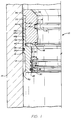
- Seal assembly 10 of the present invention is shown in its running position in FIGURE 1.
- Seal assembly 10 includes seal ring 12 and actuating ring 14. As shown in FIGURE 1, seal assembly 10 is positioned within wellhead member 16 and is being lowered therein on a suitable running tool (not shown).
- Seal ring 12 includes annular body 18 having lower rim 20 extending downward from the inner portion of body 18 and upper rim 22 extending upward from the outer portion of body 18.
- Wiper 24 is positioned within groove 26 around the exterior of body 18 and is sufficiently large to engage the interior of wellhead member 16 as seal assembly 10 is being lowered therein.
- Lower rim 20 includes groove 28 on the lower portion of its interior surface with wiper 30 being positioned therein and being sufficiently large to wipe the outer sealing surface of the hanger against which seal assembly 10 is to seal. Spaced above groove 28 is seal area 32 having sealing lips 34 and 36. Both of lips 34 and 36 extend inwardly with upper lip 34 extending upwardly and inwardly and lower lip 36 extending downwardly and inwardly. The outer diameter of lips 34 and 36 is sufficiently small to ensure proper sealing against the exterior of the hanger against which seal assembly 10 is to seal.
- Upper rim 22 includes external teeth or gripping and sealing elements or serrations 38 and internal multiple upward facing camming surfaces 40. Serrations 38 are intended to include small parallel grooves with pointed projections between the grooves.
- camming surfaces 40 terminate at flat cylindrical surfaces 40a and the outer edges of camming surfaces 40 terminate at flat cylindrical surfaces 40b so that camming surfaces 40 and cylindrical surfaces 40a and 40b form a toothed profile 40c with recesses 40d.
- Upper rim 22 extending upwardly from the outer portion of annular body 18 provides shoulder 42 on the upper part of body 18 within rim 22.
- Actuating ring 14 is annular in shape and includes inner tapered landing seat 44 on which a subsequent well member could be landed, external multiple downward facing camming surfaces 46 which mate with the camming surfaces 40 on the interior of upper rim 22.
- the outer edges of camming surfaces 46 terminate at flat cylindrical surfaces 46a and the inner edges of camming surfaces 46 terminate at flat cylindrical surfaces 46b so that camming surfaces 46 and cylindrical surfaces 46a and 46b form a toothed profile 46c with recesses 46d.
- actuating ring 14 In running position, actuating ring 14 is in its upper position, as shown in FIGURE 1, and in such position its lower surface 48 is spaced above shoulder 42 on body 18 and camming surfaces 40 and 46 are in contact.
- Toothed profiles 40c of upper rim 22 are located in recesses 46d of actuating ring 14 and toothed profiles 46c of actuating ring 14 are located in recesses 40d of upper rim 22 so that toothed profiles 40c and 46c are interlocked.
- This spacing between surfaces 42 and 48 should be sufficient to allow full travel of actuating ring 14 in its downward setting movement as hereinafter described.
- Actuating ring 14 includes an outwardly extending flange 50 at its upper end above surfaces 46 and the lower surface of flange 50 is also spaced above the upper end of upper rim 22 by a sufficient distance to allow full setting movement of actuating ring 14.
- Actuating ring 14 also includes preparation for receiving the suitable running tool (not shown).
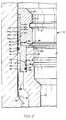
- sealing assembly 10 is landed in annular space 52 between the interior of wellhead member 16 and the exterior of hanger 54 above upwardly facing shoulder 56 of hanger 54.
- Hanger 54 is landed upon in wellhead member 16 with downwardly facing shoulder 57 of hanger 54 being in supporting contact with upwardly facing shoulder 58 of wellhead member 16 and includes the usual mud slots 55 which allow circulation of cement or other well fluids prior to the landing of seal assembly 10 in annular space 52.
- seal assembly 10 landed in annular space 52 as shown in FIGURE 2 the lower end of lower rim 20 is in engagement with shoulder 56 on hanger 54.
- wiper 30 in its downward movement has wiped external sealing surface 60 of hanger 54 free of trash, mud and all other materials which would interfere with proper sealing of lips 34 and 36 against sealing surface 60. Also, wiper 24 has wiped interior sealing surface 62 of wellhead member or housing 16 free of trash, mud and all other materials which would interfere with proper sealing of gripping teeth 38 to sealing surface 62.
- seal assembly 10 With seal assembly 10 in the position shown in FIGURE 2, it is ready for the engagement of gripping teeth 38 of upper rim 22 with sealing surface 62 of wellhead member 16. Actuating ring 14 is moved downward by a suitable tool (not shown) so that its exterior camming surfaces 46 move downward on camming surfaces 40 of upper rim 22 to wedge gripping teeth 38 into tight gripping and sealing engagement with sealing surface 62. In this position as shown in FIGURE 3, actuating ring 14 has moved to its lower position with its lower surface 48 engaging shoulder 42 on the upper portion of seal body 18 and also with the lower surface of flange 50 in engagement with the upper surface of rim 22.
- actuating ring 14 and seal ring 12 provide suitable stops for the downward movement of actuating ring 14 at a position when maximun force has been exerted on upper rim 22 to ensure positive deformation of sealing surface 62 by gripping teeth 38.
- lower inner surface 49 of actuator 14 engages upper surface 54a of hanger 54.
- These engagements provide a transfer of the load of a hanger which is subsequently landed on landing seat 44. This load is then transferred through actuating ring 14 and rim 22 into housing 16, through actuating ring 14, shoulders 42 and 48, hanger 54 and seat 58 into housing 16 and through actuating ring 14, shoulder 54a and seat 58 into housing 16.
- Cylindrical surfaces 46a of actuating ring 14 have also been moved downward to become in tight contact with cylindrical surfaces 40b of upper rim 22 and thereby eliminate any tendency of actuating ring 14 to move upward in relation to seal ring 12. Also, sealing by lips 34 and 36 against sealing surface 60 is complete and is enhanced by the configuration of the lips. Fluid pressure from the interior of hanger 54 acts on exterior surface 34a of upper lip 34 to urge lip 34 into tight sealing engagement with surface 60 of hanger 54. In a similar manner fluid pressure from the exterior of hanger 54 acts on exterior surface 36a of lower lip 36 to urge lip 36 into tight engagement with surface 60 of hanger 54. Such pressure urging of lips 34 and 36 towards surface 60 increases as the pressure increases. As can be seen in FIGURE 1, lips 34 and 36 protrude inward from surface 20 and as such are able to compensate for eccentricity between wellhead member 16 and hanger 54 and still sealingly engage surface 60.
- the exterior surface 61 of lower rim 20 is spaced substantially from the interior surface 62 of wellhead housing 16. This provides a space for the trash and mud which is wiped from surface 62 by wiper 24 so that such trash and mud cannot interfere with the sealing operations of seal assembly 10.
- Sealing assembly 10 is retrievable from its sealing position in annular space 52 by lifting actuating ring 14 with a suitable well tool (not shown) which can engage lower surface 48 which is spaced from the upper end of hanger 54 or running tool preparation.
- Lifting of actuating ring 14 moves its camming surfaces 46 upwardly to release the force exterted on upper rim 22.
- actuating ring 14 reaches its upper position as shown in FIGURES 1 and 2 the toothed profiles on actuating ring 14 and upper rim 22 again become interlocked to transmit the lifting force to seal ring 12. This upward force is sufficient to cause a release of the gripping engagement of gripping teeth 38 with sealing surface 62 to allow completion of the retrieval of seal assembly 10.
- the Brinell hardness of seal assembly 10 in the area of serrations 38 is preferably greater than the Brinell hardness of surface 62 of wellhead member 16 so that serrations 38 will bite into surface 62 when actuating ring 14 is moved downward. In some situations it may be preferable to place serrations at the appropriate location on surface 62 rather than on seal assembly 10. In such a situation it would be preferable to have the serration area of the wellhead member a higher Brinell hardness than the smooth exterior surface of the seal assembly.
- FIGURE 4 Another modified form of the present invention is shown in FIGURE 4 wherein seal assembly 110 is energized by exterior tapered surface 146 of actuating ring 114 engaging interior tapered surface 140 of upper rim 122 to urge upper rim 122 into sealing engagement with the interior surface of wellhead member 116.
- Shear pin 123 is inserted in hole 125 through rim 122 and into energizing ring 114 to retain seal assembly 110 in an unenergized position until shoulder 57 engages upwardly facing shoulder 58 of wellhead member 116.
Landscapes
- Engineering & Computer Science (AREA)
- Geology (AREA)
- Life Sciences & Earth Sciences (AREA)
- General Engineering & Computer Science (AREA)
- Mining & Mineral Resources (AREA)
- Mechanical Engineering (AREA)
- General Life Sciences & Earth Sciences (AREA)
- Geochemistry & Mineralogy (AREA)
- Environmental & Geological Engineering (AREA)
- Physics & Mathematics (AREA)
- Fluid Mechanics (AREA)
- Sealing Devices (AREA)
- Excavating Of Shafts Or Tunnels (AREA)
- Yarns And Mechanical Finishing Of Yarns Or Ropes (AREA)
- Separation By Low-Temperature Treatments (AREA)
- Polymers With Sulfur, Phosphorus Or Metals In The Main Chain (AREA)
- Seal Device For Vehicle (AREA)
- Discharge Heating (AREA)
- Measurement Of Radiation (AREA)
- Examining Or Testing Airtightness (AREA)
Abstract
Description
- This invention relates to wellhead seals.
- Wellhead seals are used to seal across the annular space between the exterior of a hanger and the interior of a wellhead housing in which the hanger is supported. Many types of seals have been used in the past. Such seals have included resilient annular members which are positioned within the annular space and compressed axially to expand them into sealing engagement with the surfaces defining the interior and exterior of the annular space, such as disclosed in U.S. Patent No. 3,797,864.
- Other seals include metal members having lips urged into engagement with the inner and outer sealing surfaces as shown in U.S. Patent Nos. 2,405,152; 2,746,486; 4,131,287; and 4,178,020. GB-A-2180016 also describes a casing hanger seal of this type.
- US-A-4131287 describes a seal for sealing in the annular space between a wellhead housing and a casing hanger. The seal comprises a body having upper and lower pairs of sealing lips. The sealing lips can be forced outwardly into sealing engagement with the hanger and wellhead housing by means of upper and lower sealing rings which are moved into the space between each pair of clips.
- Some seals have utilised a combination of resilient and metal seals such as illustrated by U.S. Patent Nos. 4,488,740 and 4,550,782.
- Additionally seals have been provided which utilise a resilient or metal seal which is mechanically wedged or cammed into sealing engagement with the walls of the annular space in a well bore. Other seal structures have included threaded or roughened sealing surfaces, such as wickers, which provide a positive metal-to-metal seal. U.S. Patent No. 4,595,053 is an example of these two types of seals.
- According to the present invention there is provided an annular wellhead seal for sealing between the interior surface of the wellhead housing and the exterior of a hanger within the housing, said housing having an internal landing seat and an internal sealing surface above the landing seat and said hanger having an external landing shoulder for engaging the internal landing seat when the hanger has been landed within the housing, and an external upwardly facing shoulder, said seal comprising a sealing ring adapted to be landed on the hanger external shoulder so that it can seal between the interior of the wellhead housing and the exterior of the hanger, and an actuating ring for moving the sealing ring to its sealing position, projections being formed on one of said sealing ring external surface or said housing internal sealing surface, and said sealing ring including internal sealing means for sealing against the exterior of the hanger, and said actuating ring having camming means which, when said actuating ring is moved downwardly, are operable to cam said sealing ring outwardly so that said projections are caused to bite into the other surface to provide a gripping and sealing engagement therebetween, characterised in that the sealing ring has a central body with an inner upwardly facing shoulder, an upper outer rim extending above the central body, and a lower rim extending below the central body, said shoulder defining an annular surface extending substantially from the outer rim to the central bore of the sealing ring body, and wherein the lower rim has the internal sealing means and the actuating ring is positioned within the upper rim and is operable to cam outwardly the upper rim to provide said gripping and said sealing engagement.
- The invention will be described now by way of example only, with particular reference to the accompanying drawings. In the drawings:
- FIGURE 1 is a partial sectional view of the improved annular wellhead seal as it is being run into a wellhead for subsequent landing within the annular space across which is it to seal.
- FIGURE 2 is another partial sectional view of the improved wellhead seal after it has been landed and prior to energisation.
- FIGURE 3 is another partial sectional view of the improved wellhead seal after it has been moved into tight sealing engagement across the annular space.
- FIGURE 4 is a partial sectional view of a modified form of the improved annular wellhead seal of the present invention.
- Improved
seal assembly 10 of the present invention is shown in its running position in FIGURE 1.Seal assembly 10 includesseal ring 12 and actuatingring 14. As shown in FIGURE 1,seal assembly 10 is positioned withinwellhead member 16 and is being lowered therein on a suitable running tool (not shown).Seal ring 12 includesannular body 18 havinglower rim 20 extending downward from the inner portion ofbody 18 andupper rim 22 extending upward from the outer portion ofbody 18. Wiper 24 is positioned withingroove 26 around the exterior ofbody 18 and is sufficiently large to engage the interior ofwellhead member 16 asseal assembly 10 is being lowered therein. -
Lower rim 20 includesgroove 28 on the lower portion of its interior surface withwiper 30 being positioned therein and being sufficiently large to wipe the outer sealing surface of the hanger against whichseal assembly 10 is to seal. Spaced abovegroove 28 is seal area 32 having sealinglips lips upper lip 34 extending upwardly and inwardly andlower lip 36 extending downwardly and inwardly. The outer diameter oflips seal assembly 10 is to seal.Upper rim 22 includes external teeth or gripping and sealing elements orserrations 38 and internal multiple upward facingcamming surfaces 40.Serrations 38 are intended to include small parallel grooves with pointed projections between the grooves. The inner edges ofcamming surfaces 40 terminate at flat cylindrical surfaces 40a and the outer edges ofcamming surfaces 40 terminate at flatcylindrical surfaces 40b so thatcamming surfaces 40 andcylindrical surfaces 40a and 40b form atoothed profile 40c with recesses 40d.Upper rim 22 extending upwardly from the outer portion ofannular body 18 providesshoulder 42 on the upper part ofbody 18 withinrim 22. - Actuating
ring 14 is annular in shape and includes innertapered landing seat 44 on which a subsequent well member could be landed, external multiple downward facingcamming surfaces 46 which mate with thecamming surfaces 40 on the interior ofupper rim 22. The outer edges ofcamming surfaces 46 terminate at flatcylindrical surfaces 46a and the inner edges ofcamming surfaces 46 terminate at flatcylindrical surfaces 46b so thatcamming surfaces 46 andcylindrical surfaces toothed profile 46c with recesses 46d. In running position, actuatingring 14 is in its upper position, as shown in FIGURE 1, and in such position itslower surface 48 is spaced aboveshoulder 42 onbody 18 andcamming surfaces Toothed profiles 40c ofupper rim 22 are located in recesses 46d of actuatingring 14 andtoothed profiles 46c of actuatingring 14 are located in recesses 40d ofupper rim 22 so thattoothed profiles surfaces ring 14 in its downward setting movement as hereinafter described. Actuatingring 14 includes an outwardly extendingflange 50 at its upper end abovesurfaces 46 and the lower surface offlange 50 is also spaced above the upper end ofupper rim 22 by a sufficient distance to allow full setting movement of actuatingring 14. Actuatingring 14 also includes preparation for receiving the suitable running tool (not shown). - As shown in FIGURE 2,
sealing assembly 10 is landed inannular space 52 between the interior ofwellhead member 16 and the exterior ofhanger 54 above upwardly facingshoulder 56 ofhanger 54. Hanger 54 is landed upon inwellhead member 16 with downwardly facingshoulder 57 ofhanger 54 being in supporting contact with upwardly facingshoulder 58 ofwellhead member 16 and includes theusual mud slots 55 which allow circulation of cement or other well fluids prior to the landing ofseal assembly 10 inannular space 52. Withseal assembly 10 landed inannular space 52 as shown in FIGURE 2 the lower end oflower rim 20 is in engagement withshoulder 56 onhanger 54. In this position, wiper 30 in its downward movement has wipedexternal sealing surface 60 ofhanger 54 free of trash, mud and all other materials which would interfere with proper sealing oflips surface 60. Also,wiper 24 has wipedinterior sealing surface 62 of wellhead member or housing 16 free of trash, mud and all other materials which would interfere with proper sealing of grippingteeth 38 to sealingsurface 62. - With
seal assembly 10 in the position shown in FIGURE 2, it is ready for the engagement of grippingteeth 38 ofupper rim 22 withsealing surface 62 ofwellhead member 16. Actuatingring 14 is moved downward by a suitable tool (not shown) so that itsexterior camming surfaces 46 move downward oncamming surfaces 40 ofupper rim 22 to wedge grippingteeth 38 into tight gripping and sealing engagement withsealing surface 62. In this position as shown in FIGURE 3, actuatingring 14 has moved to its lower position with itslower surface 48 engagingshoulder 42 on the upper portion ofseal body 18 and also with the lower surface offlange 50 in engagement with the upper surface ofrim 22. These two engagements between actuatingring 14 andseal ring 12 provide suitable stops for the downward movement of actuatingring 14 at a position when maximun force has been exerted onupper rim 22 to ensure positive deformation ofsealing surface 62 by grippingteeth 38. Also, lowerinner surface 49 ofactuator 14 engagesupper surface 54a ofhanger 54. These engagements provide a transfer of the load of a hanger which is subsequently landed onlanding seat 44. This load is then transferred through actuatingring 14 and rim 22 intohousing 16, through actuatingring 14,shoulders hanger 54 andseat 58 intohousing 16 and through actuatingring 14,shoulder 54a andseat 58 intohousing 16.Cylindrical surfaces 46a of actuatingring 14 have also been moved downward to become in tight contact withcylindrical surfaces 40b ofupper rim 22 and thereby eliminate any tendency of actuatingring 14 to move upward in relation toseal ring 12. Also, sealing bylips surface 60 is complete and is enhanced by the configuration of the lips. Fluid pressure from the interior ofhanger 54 acts on exterior surface 34a ofupper lip 34 to urgelip 34 into tight sealing engagement withsurface 60 ofhanger 54. In a similar manner fluid pressure from the exterior ofhanger 54 acts on exterior surface 36a oflower lip 36 to urgelip 36 into tight engagement withsurface 60 ofhanger 54. Such pressure urging oflips surface 60 increases as the pressure increases. As can be seen in FIGURE 1,lips surface 20 and as such are able to compensate for eccentricity betweenwellhead member 16 andhanger 54 and still sealingly engagesurface 60. - It should be noted that the
exterior surface 61 oflower rim 20 is spaced substantially from theinterior surface 62 ofwellhead housing 16. This provides a space for the trash and mud which is wiped fromsurface 62 bywiper 24 so that such trash and mud cannot interfere with the sealing operations ofseal assembly 10. -
Sealing assembly 10 is retrievable from its sealing position inannular space 52 by lifting actuatingring 14 with a suitable well tool (not shown) which can engagelower surface 48 which is spaced from the upper end ofhanger 54 or running tool preparation. Lifting of actuatingring 14 moves itscamming surfaces 46 upwardly to release the force exterted onupper rim 22. When actuatingring 14 reaches its upper position as shown in FIGURES 1 and 2, the toothed profiles on actuatingring 14 andupper rim 22 again become interlocked to transmit the lifting force to sealring 12. This upward force is sufficient to cause a release of the gripping engagement ofgripping teeth 38 with sealingsurface 62 to allow completion of the retrieval ofseal assembly 10. - Sometimes well debris, such as gravel or clay, becomes deposited on upwardly facing
shoulder 58 ofwellhead member 16 and prevents downwardly facingshoulder 57 ofhanger 54 from contactingshoulder 58. Pressure subsequently present in the interior ofhanger 54 may crush the debris and causehanger 54 to move downward relative towellhead member 16 and sealingassembly 10. Since sealinglips hanger seal surface 60, such relative vertical movement between the sealing lips andsurface 60 does not compromise the sealing engagement of thelips - It should be recognized in the preferred embodiment of FIGURES 1, 2 and 3 that the Brinell hardness of
seal assembly 10 in the area ofserrations 38 is preferably greater than the Brinell hardness ofsurface 62 ofwellhead member 16 so thatserrations 38 will bite intosurface 62 when actuatingring 14 is moved downward. In some situations it may be preferable to place serrations at the appropriate location onsurface 62 rather than onseal assembly 10. In such a situation it would be preferable to have the serration area of the wellhead member a higher Brinell hardness than the smooth exterior surface of the seal assembly. - It should be noted that in most wellhead sealing situations, the condition of the sealing surface on the exterior of the hanger is known to be satisfactory while the condition of the sealing surface of the interior of the wellhead housing is unpredictable. The present invention provides an improved metal-to-metal seal against both such surfaces.
- Another modified form of the present invention is shown in FIGURE 4 wherein
seal assembly 110 is energized by exterior taperedsurface 146 ofactuating ring 114 engaging interior taperedsurface 140 of upper rim 122 to urge upper rim 122 into sealing engagement with the interior surface ofwellhead member 116.Shear pin 123 is inserted inhole 125 through rim 122 and into energizingring 114 to retainseal assembly 110 in an unenergized position untilshoulder 57 engages upwardly facingshoulder 58 ofwellhead member 116.
Claims (11)
- An annular wellhead seal for sealing between the interior surface of the wellhead housing (16) and the exterior of a hanger (54) within the housing, said housing (16) having an internal landing seat (58) and an internal sealing surface (62) above the landing seat and said hanger (54) having an external landing shoulder (57) for engaging the internal landing seat (58) when the hanger has been landed within the housing, and an external upwardly facing shoulder (56), said seal comprising a sealing ring (12) adapted to be landed on the hanger external shoulder (56) so that it can seal between the interior of the wellhead housing and the exterior of the hanger, and an actuating ring (14) for moving the sealing ring to its sealing position, projections (38) being formed on one of said sealing ring external surface or said housing internal sealing surface (62), and said sealing ring including internal sealing means (34, 36) for sealing against the exterior of the hanger, and said actuating ring (14) having camming means (46) which, when said actuating ring is moved downwardly, are operable to cam said sealing ring outwardly so that said projections (38) are caused to bite into the other surface to provide a gripping and sealing engagement therebetween, characterised in that the sealing ring (12) has a central body with an inner upwardly facing shoulder (42), an upper outer rim (22) extending above the central body, and a lower rim (20) extending below the central body, said inner upwardly facing shoulder (42) defining an annular surface extending substantially from the upper outer rim (22) to the central bore of the sealing ring body, and wherein the lower rim (20) has the internal sealing means (34, 36) and the actuating ring is positioned within the upper rim and is operable to cam outwardly the upper outer rim (22) to provide said gripping and said sealing engagement.
- An annular wellhead seal according to claim 1, wherein said projections (38) are positioned on the exterior of the upper rim (22).
- An annular wellhead seal according to claim 1 or claim 2, wherein said camming means (46) are between the interior of said sealing ring (12) and the exterior of said actuating ring (14).
- An annular wellhead seal according to any preceding claim, wherein said internal sealing means (34, 36) includes a resilient sealing ring positioned for sealing against the exterior of said hanger.
- An annular wellhead seal according claim 4, wherein said internal sealing means includes an upper metal sealing lip (34) extending upwardly and inwardly, and a lower metal sealing lip (36) extending downwardly and inwardly, said upper and lower metal sealing lips being sized to provide sealing engagement with the exterior of said hanger.
- An annular wellhead seal according to claim 1, wherein said projections (38) include a plurality of teeth.
- An annular wellhead seal according to claim 1, wherein said camming means (46) includes a plurality of camming surfaces (40) on the interior of said sealing ring (12) and a plurality of coacting camming surfaces (46) on the exterior of the actuating ring (14).
- An annular wellhead seal according to claim 1, wherein said coming means includes a tapered surface (146) on the exterior of the actuating ring (114) which engages a tapered surface (140) on the interior of the upper rim (122).
- An annular wellhead seal according to any preceding claim wherein said inner upwardly facing shoulder (42) acts as a limit to the downward travel of the actuating ring (14).
- An annular wellhead seal according to any preceding claim, including a wiper (24) carried by said seal ring (12) on its exterior below said upper rim (22) for wiping trash, mud, and other material from the sealing surface against which said upper rim is to seal.
- An annular wellhead seal according to any preceding claim, including a wiper (30) carried by the lower rim (20) for wiping trash, mud and other material from the sealing surface against which the lower rim is to seal.
Priority Applications (1)
| Application Number | Priority Date | Filing Date | Title |
|---|---|---|---|
| AT88300167T ATE101237T1 (en) | 1987-04-30 | 1988-01-11 | WELL HEAD SEAL. |
Applications Claiming Priority (2)
| Application Number | Priority Date | Filing Date | Title |
|---|---|---|---|
| US07/044,410 US4791987A (en) | 1987-04-30 | 1987-04-30 | Wellhead seal |
| US44410 | 1987-04-30 |
Publications (3)
| Publication Number | Publication Date |
|---|---|
| EP0289105A2 EP0289105A2 (en) | 1988-11-02 |
| EP0289105A3 EP0289105A3 (en) | 1989-08-16 |
| EP0289105B1 true EP0289105B1 (en) | 1994-02-02 |
Family
ID=21932237
Family Applications (1)
| Application Number | Title | Priority Date | Filing Date |
|---|---|---|---|
| EP88300167A Expired - Lifetime EP0289105B1 (en) | 1987-04-30 | 1988-01-11 | Wellhead seal |
Country Status (9)
| Country | Link |
|---|---|
| US (1) | US4791987A (en) |
| EP (1) | EP0289105B1 (en) |
| JP (1) | JPS63272889A (en) |
| AT (1) | ATE101237T1 (en) |
| AU (1) | AU606372B2 (en) |
| BR (1) | BR8801896A (en) |
| CA (1) | CA1289063C (en) |
| DE (1) | DE3887558T2 (en) |
| NO (1) | NO881872L (en) |
Families Citing this family (24)
| Publication number | Priority date | Publication date | Assignee | Title |
|---|---|---|---|---|
| US4832125A (en) * | 1987-04-30 | 1989-05-23 | Cameron Iron Works Usa, Inc. | Wellhead hanger and seal |
| US4925220A (en) * | 1988-12-16 | 1990-05-15 | Cameron Iron Works U.S.A., Inc. | Tubular joint |
| US4901794A (en) * | 1989-01-23 | 1990-02-20 | Baker Hughes Incorporated | Subterranean well anchoring apparatus |
| US4949787A (en) * | 1989-04-07 | 1990-08-21 | Vetco Gray Inc. | Casing hanger seal locking mechanism |
| US4949786A (en) * | 1989-04-07 | 1990-08-21 | Vecto Gray Inc. | Emergency casing hanger |
| US5060724A (en) * | 1989-04-07 | 1991-10-29 | Abb Vetco Gray Inc. | Casing hanger seal locking mechanism with detent |
| US5026074A (en) * | 1989-06-30 | 1991-06-25 | Cooper Industries, Inc. | Annular metal-to-metal seal |
| US5039140A (en) * | 1989-08-22 | 1991-08-13 | Cooper Industries, Inc. | Wellhead joint and sealing ring |
| GB8920607D0 (en) * | 1989-09-12 | 1989-10-25 | Tri State Oil Tool Uk | Metal seal casing patch |
| US5094297A (en) * | 1990-10-30 | 1992-03-10 | Abb Vetco Gray Inc. | Casing weight set seal ring |
| US5174376A (en) * | 1990-12-21 | 1992-12-29 | Fmc Corporation | Metal-to-metal annulus packoff for a subsea wellhead system |
| US5101897A (en) * | 1991-01-14 | 1992-04-07 | Camco International Inc. | Slip mechanism for a well tool |
| US5183268A (en) * | 1991-04-30 | 1993-02-02 | Fmc Corporation | Metal-to-metal wellhead seal for rough casing |
| US5226484A (en) * | 1991-12-19 | 1993-07-13 | Abb Vetco Gray Inc. | Emergency casing support using standard casing hanger |
| US5511620A (en) * | 1992-01-29 | 1996-04-30 | Baugh; John L. | Straight Bore metal-to-metal wellbore seal apparatus and method of sealing in a wellbore |
| US5333692A (en) * | 1992-01-29 | 1994-08-02 | Baker Hughes Incorporated | Straight bore metal-to-metal wellbore seal apparatus and method of sealing in a wellbore |
| US5364110A (en) * | 1992-12-11 | 1994-11-15 | Halliburton Company | Downhole tool metal-to-metal seal |
| US5375812A (en) * | 1993-12-06 | 1994-12-27 | Abb Vetco Gray Inc. | Dynamic metal-to-metal seal |
| US6032958A (en) * | 1998-03-31 | 2000-03-07 | Hydril Company | Bi-directional pressure-energized metal seal |
| US6752397B2 (en) * | 2001-12-18 | 2004-06-22 | Schlumberger Technology Corporation | Redundant metal-metal seal |
| US7220067B2 (en) * | 2004-03-24 | 2007-05-22 | Schlumberger Technology Corporation | Cable splice protector |
| US7469750B2 (en) * | 2004-09-20 | 2008-12-30 | Owen Oil Tools Lp | Expandable seal |
| US7740080B2 (en) * | 2007-11-27 | 2010-06-22 | Vetco Gray Inc. | Pressure energized seal |
| US9732582B2 (en) * | 2014-09-26 | 2017-08-15 | Vetco Gray Inc. | Wellbore sealing with hybrid wicker system |
Family Cites Families (11)
| Publication number | Priority date | Publication date | Assignee | Title |
|---|---|---|---|---|
| US466597A (en) * | 1892-01-05 | Test-frame and trial-lens for eyes | ||
| BE620892A (en) * | ||||
| US1683640A (en) * | 1919-08-12 | 1928-09-11 | Howard F Smith | Sealing device |
| US2953406A (en) * | 1958-11-24 | 1960-09-20 | A D Timmons | Casing spear |
| SE346031B (en) * | 1970-03-02 | 1972-06-19 | Forsheda Gummifabrik Ab | |
| US4131287A (en) * | 1977-07-11 | 1978-12-26 | Exxon Production Research Company | Annular seal |
| US4178020A (en) * | 1977-12-15 | 1979-12-11 | Big-Inch Marine Systems, Inc. | Locking slip joint and method of use |
| US4573537A (en) * | 1981-05-07 | 1986-03-04 | L'garde, Inc. | Casing packer |
| US4595053A (en) * | 1984-06-20 | 1986-06-17 | Hughes Tool Company | Metal-to-metal seal casing hanger |
| US4665979A (en) * | 1985-09-06 | 1987-05-19 | Hughes Tool Company | Metal casing hanger seal with expansion slots |
| US4650225A (en) * | 1986-03-31 | 1987-03-17 | Joy Manufacturing Company | Hydraulic holddown screw with mechanical retention means |
-
1987
- 1987-04-30 US US07/044,410 patent/US4791987A/en not_active Expired - Fee Related
-
1988
- 1988-01-06 AU AU10094/88A patent/AU606372B2/en not_active Ceased
- 1988-01-11 DE DE88300167T patent/DE3887558T2/en not_active Expired - Fee Related
- 1988-01-11 AT AT88300167T patent/ATE101237T1/en not_active IP Right Cessation
- 1988-01-11 EP EP88300167A patent/EP0289105B1/en not_active Expired - Lifetime
- 1988-01-15 CA CA000556641A patent/CA1289063C/en not_active Expired - Fee Related
- 1988-02-22 JP JP63039319A patent/JPS63272889A/en active Pending
- 1988-04-21 BR BR8801896A patent/BR8801896A/en not_active IP Right Cessation
- 1988-04-29 NO NO881872A patent/NO881872L/en unknown
Also Published As
| Publication number | Publication date |
|---|---|
| EP0289105A3 (en) | 1989-08-16 |
| NO881872D0 (en) | 1988-04-29 |
| US4791987A (en) | 1988-12-20 |
| CA1289063C (en) | 1991-09-17 |
| AU606372B2 (en) | 1991-02-07 |
| NO881872L (en) | 1988-10-31 |
| EP0289105A2 (en) | 1988-11-02 |
| AU1009488A (en) | 1988-11-03 |
| DE3887558D1 (en) | 1994-03-17 |
| ATE101237T1 (en) | 1994-02-15 |
| BR8801896A (en) | 1988-11-22 |
| JPS63272889A (en) | 1988-11-10 |
| DE3887558T2 (en) | 1994-05-11 |
Similar Documents
| Publication | Publication Date | Title |
|---|---|---|
| US4791987A (en) | Wellhead seal | |
| US4751965A (en) | Wellhead seal assembly | |
| US4719971A (en) | Metal-to-metal/elastomeric pack-off assembly for subsea wellhead systems | |
| EP0289104B1 (en) | Annular wellhead seal | |
| US5060724A (en) | Casing hanger seal locking mechanism with detent | |
| US4714111A (en) | Weight/pressure set pack-off for subsea wellhead systems | |
| US3623551A (en) | Anchoring apparatus for a well packer | |
| CA1162146A (en) | Well packer | |
| US4949787A (en) | Casing hanger seal locking mechanism | |
| CA1291705C (en) | Wellhead hanger and seal | |
| US4651818A (en) | Metal seal tubing plug | |
| US5456321A (en) | Tubing hanger incorporating a seal | |
| JP2511486B2 (en) | Well head seal | |
| GB2104170A (en) | Lockdown mechanism for wellhead connector | |
| US4790379A (en) | Wellhead hanger | |
| EP0475557A1 (en) | Method of sealing a casing hanger in a wellhead | |
| EP0290112B1 (en) | Subsea wellhead seal assembly | |
| US5330002A (en) | Hanger assembly | |
| GB2180016A (en) | Casing hanger seal | |
| US10138698B2 (en) | External locking mechanism for seal energizing ring | |
| CA1281282C (en) | Wellhead seals | |
| EP0359355B1 (en) | Wellhead slip and seal assembly | |
| GB2585548A (en) | Self-locking packer carrier | |
| US4784222A (en) | Wellhead sealing assembly | |
| US4722391A (en) | Wellhead system |
Legal Events
| Date | Code | Title | Description |
|---|---|---|---|
| PUAI | Public reference made under article 153(3) epc to a published international application that has entered the european phase |
Free format text: ORIGINAL CODE: 0009012 |
|
| AK | Designated contracting states |
Kind code of ref document: A2 Designated state(s): AT DE FR GB NL |
|
| PUAL | Search report despatched |
Free format text: ORIGINAL CODE: 0009013 |
|
| AK | Designated contracting states |
Kind code of ref document: A3 Designated state(s): AT DE FR GB NL |
|
| RAP1 | Party data changed (applicant data changed or rights of an application transferred) |
Owner name: CAMERON IRON WORKS USA, INC. (A DELAWARE CORP.) |
|
| 17P | Request for examination filed |
Effective date: 19900122 |
|
| RAP1 | Party data changed (applicant data changed or rights of an application transferred) |
Owner name: COOPER INDUSTRIES INC. |
|
| 17Q | First examination report despatched |
Effective date: 19910806 |
|
| GRAA | (expected) grant |
Free format text: ORIGINAL CODE: 0009210 |
|
| AK | Designated contracting states |
Kind code of ref document: B1 Designated state(s): AT DE FR GB NL |
|
| REF | Corresponds to: |
Ref document number: 101237 Country of ref document: AT Date of ref document: 19940215 Kind code of ref document: T |
|
| REF | Corresponds to: |
Ref document number: 3887558 Country of ref document: DE Date of ref document: 19940317 |
|
| ET | Fr: translation filed | ||
| PLBE | No opposition filed within time limit |
Free format text: ORIGINAL CODE: 0009261 |
|
| STAA | Information on the status of an ep patent application or granted ep patent |
Free format text: STATUS: NO OPPOSITION FILED WITHIN TIME LIMIT |
|
| PG25 | Lapsed in a contracting state [announced via postgrant information from national office to epo] |
Ref country code: GB Effective date: 19950111 Ref country code: AT Effective date: 19950111 |
|
| 26N | No opposition filed | ||
| PG25 | Lapsed in a contracting state [announced via postgrant information from national office to epo] |
Ref country code: NL Effective date: 19950801 |
|
| GBPC | Gb: european patent ceased through non-payment of renewal fee |
Effective date: 19950111 |
|
| PG25 | Lapsed in a contracting state [announced via postgrant information from national office to epo] |
Ref country code: FR Effective date: 19950929 |
|
| NLV4 | Nl: lapsed or anulled due to non-payment of the annual fee |
Effective date: 19950801 |
|
| PG25 | Lapsed in a contracting state [announced via postgrant information from national office to epo] |
Ref country code: DE Effective date: 19951003 |
|
| REG | Reference to a national code |
Ref country code: FR Ref legal event code: ST |