EP0288914B1 - Method and assembly for container loading and unloading - Google Patents
Method and assembly for container loading and unloading Download PDFInfo
- Publication number
- EP0288914B1 EP0288914B1 EP88106434A EP88106434A EP0288914B1 EP 0288914 B1 EP0288914 B1 EP 0288914B1 EP 88106434 A EP88106434 A EP 88106434A EP 88106434 A EP88106434 A EP 88106434A EP 0288914 B1 EP0288914 B1 EP 0288914B1
- Authority
- EP
- European Patent Office
- Prior art keywords
- fingers
- finger
- pallet
- air
- assembly
- Prior art date
- Legal status (The legal status is an assumption and is not a legal conclusion. Google has not performed a legal analysis and makes no representation as to the accuracy of the status listed.)
- Expired - Lifetime
Links
- 238000000034 method Methods 0.000 title claims description 16
- 239000000463 material Substances 0.000 claims description 48
- 230000000694 effects Effects 0.000 claims description 3
- 230000000284 resting effect Effects 0.000 claims description 2
- 239000002184 metal Substances 0.000 description 9
- 230000008878 coupling Effects 0.000 description 7
- 238000010168 coupling process Methods 0.000 description 7
- 238000005859 coupling reaction Methods 0.000 description 7
- 239000002985 plastic film Substances 0.000 description 4
- 229910000831 Steel Inorganic materials 0.000 description 3
- 239000010959 steel Substances 0.000 description 3
- 229920002457 flexible plastic Polymers 0.000 description 2
- 238000012986 modification Methods 0.000 description 2
- 230000004048 modification Effects 0.000 description 2
- 239000004033 plastic Substances 0.000 description 2
- 229920003023 plastic Polymers 0.000 description 2
- 239000005060 rubber Substances 0.000 description 2
- 125000006850 spacer group Chemical group 0.000 description 2
- 239000004677 Nylon Substances 0.000 description 1
- 210000004712 air sac Anatomy 0.000 description 1
- 238000000429 assembly Methods 0.000 description 1
- 230000000712 assembly Effects 0.000 description 1
- 238000010276 construction Methods 0.000 description 1
- 230000001050 lubricating effect Effects 0.000 description 1
- 230000013011 mating Effects 0.000 description 1
- 210000002445 nipple Anatomy 0.000 description 1
- 229920001778 nylon Polymers 0.000 description 1
- 230000037361 pathway Effects 0.000 description 1
- 239000002990 reinforced plastic Substances 0.000 description 1
- 239000012858 resilient material Substances 0.000 description 1
- 230000007704 transition Effects 0.000 description 1
Images




Classifications
-
- B—PERFORMING OPERATIONS; TRANSPORTING
- B65—CONVEYING; PACKING; STORING; HANDLING THIN OR FILAMENTARY MATERIAL
- B65G—TRANSPORT OR STORAGE DEVICES, e.g. CONVEYORS FOR LOADING OR TIPPING, SHOP CONVEYOR SYSTEMS OR PNEUMATIC TUBE CONVEYORS
- B65G7/00—Devices for assisting manual moving or tilting heavy loads
- B65G7/02—Devices adapted to be interposed between loads and the ground or floor, e.g. crowbars with means for assisting conveyance of loads
- B65G7/06—Devices adapted to be interposed between loads and the ground or floor, e.g. crowbars with means for assisting conveyance of loads using fluid at high pressure supplied from an independent source to provide a cushion between load and ground
-
- B—PERFORMING OPERATIONS; TRANSPORTING
- B60—VEHICLES IN GENERAL
- B60P—VEHICLES ADAPTED FOR LOAD TRANSPORTATION OR TO TRANSPORT, TO CARRY, OR TO COMPRISE SPECIAL LOADS OR OBJECTS
- B60P1/00—Vehicles predominantly for transporting loads and modified to facilitate loading, consolidating the load, or unloading
- B60P1/02—Vehicles predominantly for transporting loads and modified to facilitate loading, consolidating the load, or unloading with parallel up-and-down movement of load supporting or containing element
Definitions
- Transport containers Conventionly are in 6m (20 feet) and 12m (40 feet) sizes, and a wide variety of goods--but by no means all types of goods--can be transported by container.
- transport containers are loaded and unloaded using fork lifts, and like devices.
- fork lifts and like devices.
- 15-30 cm (6-12 inches) clearance space must be provided at the top of the goods in the container to allow effective access by a fork lift or the like, and container loading and unloading time can be significant.
- an assembly and method are provided for loading and unloading overseas transport containers that decrease the amount of head space that need be provided in the container (thereby increasing the amount of space for receipt of goods), enhance the variety of goods that can be effectively transported by container, can provide effective loading and unloading of the container (requiring only one operator) in approximately one minute, and accomplish these advantageous results in a simple, effective, and relatively inexpensive manner, the assembly structure utilizible for loading and unloading being less expensive than present conventional equipment.
- US-A-3,958,701 discloses an assembly for moving a heavy load out of or into an overseas transport container comprising rollers for the actual active loading or unloading a container, and some other structure is necessary in order to bring the load to the cargo holder of channel steel that is mounted right in front of the container. It does not provide a hand truck with a handle, but merely provides a motor for powering the wheels. The device is totally impractical for moving cargo where any deviation from a straight line is necessary.
- the invention relates to an assembly for moving a heavy load out of or into an overseas transport container, comprising: first and second substantially identical fingers of relatively rigid material, each having first and second ends, the height of said fingers being such that they may be inserted underneath a pallet to effect lifting of the pallet; at least one inflatable load bar extending along the length of the top of each of said finger; a structural cross-member holding said first and second fingers together at said first ends thereof, so that they are spaced laterally from each other and extend substantially parallel to each other from said structural cross-member; means for supplying air under pressure to said load bars, said means mounted in operative association with said structural cross-member; and a powered hand truck mounted to said structural cross-member having a handle and a driven wheel steered by said handle for effecting horizontal movement of the assembly; a plurality of air bearings disposed along the length of the bottom of each of said fingers, and each air bearing operatively connected to a source of air under pressure associated with its respective finger; and a manifold for supplying air under pressure to both said fingers
- the above object is also achieved by a method of loading or unloading an overseas transport container about 6m (20 feet) long with goods mounted on a pallet, the pallet with goods completely effectively filling the container, utilizing an assembly for moving heavy load as recited in any of claims 1 to 5, said method comprising the steps of: (a) inflating the air bearings; (b) moving fingers underneath the pallet by manipulating the handle of the hand truck; (c) inflating the load bars to lift the pallet off of a horizontal surface on which it is resting; (d) moving the pallet linearly into, or out of, a transport container with the pallet vertically supported only by the air inflating the bladders and load bars; (e) deflating the load bars; and (f) removing the fingers, at the same time, from underneath the pallet; characterized in that steps (a) and (f) are practiced by moving the fingers simultaneously and together beneath the pallet and out from the pallet.
- third and fourth fingers are connected up to the first and second fingers, and then steps (a) through (f) are practiced as set forth above.
- steps (a) through (f) are practiced as set forth above.
- the assembly (with mounted pallet(s) and goods) can be moved laterally utilizing the steerable wheel of the hand truck.
- an automated system and method are provided for disposing sheet material over the deck surface to be traversed during loading and unloading of containers, so as to make such loading and unloading as trouble free as possible. While the invention is particularly described with respect to assemblies and methods for loading and unloading transport containers, the invention also has applicability to other situations in which it is desirable to dispense, and then retract, flexible sheet material.
- An assembly according to the invention includes at least one finger having a plurality of air bearings disposed along the bottom thereof, the air bearings connected to a source of air under pressure associated with the finger.
- the height of the finger is such that it may be inserted underneath a pallet to effect lifting of the pallet.
- a coiled supply of sheet material capable of providing a smooth surface for the air bearings is preferably mounted on a front end of the finger.
- Means are provided for supplying a constant tension to the supply of sheet material, preferably an air driven motor mounted to the front end of the finger and connected to it by gears or the like for applying a tension of about 10 lbs. per square inch to the sheet material.
- An engaging means for engaging a free end of the sheet material is preferably mounted at a predetermined point along the deck surface.
- the sheet material engaging means may comprise a hook or a magnet mounted in a recess in the deck surface, and the free end of the sheet material may contain a metal bar around which the sheet material is wrapped.
- a method of facilitating movement of a load over a deck surface is also provided, utilizing at least one finger having air bearings disposed along the bottom thereof, and plastic sheet material adapted to be disposed on the deck surface below the air bearings so as to smooth the deck surface and facilitate movement of the air bearings, and load carried thereby, thereover, the method comprising the steps of: (a) Automatically dispensing the sheet material so that as the finger moves over the deck surface the sheet material will be provided between the air bearings and the deck surface over a significant portion of the length of travel thereof. And, (b) automatically taking up the sheet material as the finger moves in a reverse direction with respect to the deck.
- steps (a) and (b) are practiced by: mounting a coil of sheet material to a front end of the finger; applying a constant tension to the sheet material; and engaging a free end of the sheet material to hold it stationary with respect to the deck while the finger moves over the deck.
- apparatus for the automatic dispensing of sheet material comprising: A frame.
- a shaft mounted for rotation with respect to the frame, the shaft having sheet material coiled therearound, the sheet material including a free end having an engageable means associated therewith.
- Means mounted on the frame for supplying a force to the shaft so that constant tension is applied to the sheet material as it is dispensed from the shaft; and means for engaging the engageable means at the free end of the sheet material and to hold the free end stationary while the frame moves with respect to the engaging means, so that the sheet material is dispensed below the frame.
- An exemplary assembly 10 includes at least first and second fingers 11, 12, and when utilized for loading or unloading a 12m (40 foot) container, third and fourth fingers 13, 14 are provided.
- the fingers preferably are constructed of a relatively rigid material, such as steel.
- Each finger has first and second ends; the first and second fingers 11, 12 have first ends 15, 16 and second ends 17, 18, respectively, while the third and fourth fingers 13, 14, have first ends 19, 20, and second ends 21, 22, respectively.
- Each of the fingers 11-14 has a plurality of air bearings 24 on the bottom thereof.
- each finger Preferably seven conventional air bearings 24 are provided associated with each finger, each finger being between about 5.7 and 6m (19 and 20 feet) long.
- the air bearings may be obtained commercially from Air Float Corporation of Decatur, Illinois, or others. Each bearing has a lift capability of about 3628 kg (8,000 pounds). Air under pressure is supplied to the bearings at about 1,1 bar (16 psi) and discharged at about 0,273 bar (4 psi) (a low pressure system) and the air flow is typically about 0,266 m3/s (16 cubic feet per minute) per bearing (although it can be as low as 0,133 m3/s (8 ft. 3/min.) per bearing and still function). If desired, check valves may be incorporated in the bearings in order to provide greater stability for maneuverability and shifting loads.
- Each finger 11-14 also has associated therewith, on the top surface thereof, at least one load bar, and preferably a pair of inflatable load bars 26.
- the load bars are of inflatable, wear-resistant material. The free ends of the load bars 26 are inserted into slots in the vertical faces of the fingers 11-14, as illustrated at 26′ in FIGURE 5.
- a central tubular portion is provided for each of the fingers 11-14 to supply air through the fingers to the air bladders 24.
- the supply of air to the bearings may be provided by perforations (not shown) in the bottom of the central tubular portions communicating with each of the bearings using a conventional short pipe nipple (not shown) for each bladder.
- the central tubular portions for the fingers 11-14 are illustrated by reference numerals 28, 29, 30, and 31, respectively.
- a combined metal structural cross-member and manifold 33 is connected to the first ends 15, 16 of the fingers 11, 12.
- a commercially available powered hand truck also known as a tractor
- the hand truck 34 includes an inflatable bladder 35, which is utilized to facilitate transfer of some of the load from the fingers 11, 12 to the hand truck; a handle 36 which includes controls for the hand truck thereon; and a steerable wheel 37.
- a support 38 rigidly attached to the member 33 connects the element 33 to the hand truck 34, as does a link 38′.
- each of the fingers 11, 12 may be interconnected to the element 33 is illustrated schematically in FIGURE 3 (for the element 11).
- a flange 41 having a pair of bolt receiving openings therein, extends downwardly from the end of the element 33, and cooperates with a portion 42 of the finger 11, the portion 42 also having a pair of openings therein for receipt of bolts 43 or like fasteners.
- Another set of flanges and fasteners is provided on the opposite side of the first end 15 of the finger 11.
- FIGURE 4 illustrates an exemplary interconnection between aligned fingers, in this case between the first and third fingers 11, 13.
- the central tubular air passageways 28, 30 are interconnected in air-tight relationship utilizing resilient material gaskets 46, 47 (e g., of rubber), and metal (e.g., steel) ring 48.
- Gaskets 46, 47 have the same approximate circumferential configuration as the tubular passageways of the portions 30, 28, respectively, and engage the portions 30, 20, surrounding the hollow passageways therein.
- the metal ring 48 is sandwiched between the gaskets 46, 47.
- the fingers 11, 13 are held together by the sets of bolts 49 illustrated in FIGURE 4 at opposite sides thereof, the bolts 49 cooperating with openings (not shown) in the portions 49′ of the fingers 11, 13.
- FIGURE 5 illustrates an end termination of the fingers 13, 14, in particular, the end termination of the finger 13 being illustrated.
- a plate 50 having the same approximate configuration as the circumference of the tubular passageway of the portion 30 fits over and blocks the passageway in the portion 30 with a gasket 51 between the plate and the finger 13.
- Bolts 52 or the like hold the plate 50 in place on the element 13.
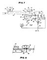
- FIGURES 6 and 7 illustrate the various structures utilized to supply air to both the manifold 33 (ultimately supplied to the tubular portions 28-31 of the fingers 11-14, respectively), and also for supplying air to the load bars 26 for each of the fingers.
- the air-ports 44, 54 in the manifold 33 supply air from the interior of the manifold 33 to the finger tubular portions 28, 29, respectively, a T-connection 55 supplying air to the manifold 33.
- the line (hose) 56 is connected to a source of compressed air at about 6,89 bar (100 psi) at the loading dock.
- Preferably quick connect/disconnect couplings 57 are provided for connection of the air hose 56 to the structure 39. Air passes through coupling 57 to the main on/off valve 58, which is preferably a hand operated ball valve. The air then passes through T-connection 59 to pressure regulator 60 for the air bearings (providing about a 1,1 bar (16 psi) maximum).
- the regulator 60 is connected to T-connection 61 which in turn is connected to the load on/off 31,75 mm (1 1/4 inch) hand operated ball valve 62, which in turn is connected to the adjustable load flow hand operated gate valve 63, and then to the connection 55. Also connected to connection 55 is the one inch hand operated globe valve 64, T-connection 65, quick connect/disconnect couplings 66, and line 67 which is the exhaust air line from the tractor 34.
- the other connection of the T-connection 65 is connected up to T-connection 68 and to relief valve 69 (preferably set at 20 psi maximum).
- Air is also supplied from hose 56 to the load bars 26.
- Connector 59 is also connected to T-connection 70, which in turn is connected to regulator 71, hand-operated 3-way valve 72, and manifolds 73, 74.
- Extending from manifolds 73, 74 are hoses 75-78, the hoses 76 are connected to the load bars for the finger 11, the hoses 75 ultimately are connected to the load bars for the finger 13, the hoses 78 are connected to the load bars for the finger 12, and the hoses 77 are ultimately connected to the load bars for the finger 14.
- the T-connector 70 is also connected through quick disconnect couplings 79 to the line 80 for supplying air to the tractor 34.
- FIGURE 8 illustrates the manner in which a hose is connected to a load bar 26, in this case for the first finger 11.
- the hose 76 passes from the manifold 73 through an opening in the finger to the bottom of the finger, as illustrated in FIGURE 8.
- Disposed in the interior of the load bar 26 is a nut 81 which receives the threaded end 83 of an L-shaped connector 82, the connector 82 end 84 being connected to the hose 76.
- FIGURE 4 also illustrated the manner in which air is supplied to the load bars 26 associated with the third and fourth connectors, in this case for the third connector 13.
- the hoses 75 are provided with couplings 86 at the ends thereof, and those couplings 86 cooperate with mating couplings 88 associated with hose sections 87 mounted on the finger 13 and passing from the top to the bottom thereof (the connection of the hose sections 87 to the load bars 26 associated therewith being the same as illustrated for the hose section 76 in FIGURE 8).
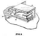
- FIGURE 9 An exemplary assembly 10 according to the invention having been described, an exemplary method according to the invention, which utilizes the assembly 10, will now be described, with reference in particular to FIGURE 9.
- the method may comprise or consist of the recited steps, which preferably are practiced sequentially as set forth.
- the air hose 56 is connected to the structure 39 by the elements 57, the main valve 58 and the load on/off valve 62 are opened, and the load flow valve 63 is adjusted to provide the desired flow to the manifold 33.
- a single operator then moves the fingers 11, 13 simultaneously (being connected by the combined structural cross-member/manifold 33) so that they are inserted beneath the pallet 96, between the spacers 97 thereof, the pallet 96 adapted to be loaded into or unloaded from the long distance transport container 95.
- the spacers 97 are preferably about 5 inches high.
- the manually operated three-way valve 72 is operated to supply air under pressure to the manifolds 73, 74, which in turn supply air under pressure to the load bars 26 associated with the fingers 11, 13.
- the inflation of the load bars 26 causes the pallet 96 to be lifted off of the horizontal surface on which it is disposed.
- the hand truck 34 may be operated to move the pallet 96 into or out of the container 95. Because of a construction of the assembly 10, only 2 inches of clearance are necessary between the pallet 96 (with goods thereon) and the top of the container 95, whereas about 6 inches of clearance is necessary if the loading/unloading is done with a conventional fork lift.
- the assembly 10 may be moved laterally, with the pallet 96 supported thereby, to facilitate direct transfer of the pallet 96 from the container 95 to a truck, train car, or the like that is at the loading dock.
- the third and fourth fingers 13, 14 are connected up to the first and second fingers 11, 12, and the steps set forth above performed as indicated, the assembly in this case supporting the pallet (or pallets) which completely fill a container that is 40 feet long.
- 4 mil flexible plastic sheeting 98 may be laid over a container 95 bottom, a sheet metal bridge between the container 95 and the loading dock 99, and/or other portions of the pathway to be traversed, to provide a non-porous smooth surface for the air casters to move over. This is preferably done as illustrated in FIGURES 10-16.
- FIGURES 10-16 an apparatus is provided for automatically dispensing sheet material beneath the fingers 11 through 14 so that they traverse as smooth a surface as possible during movement of a load thereby.
- the basic components of the apparatus for automatically dispensing sheet material are illustrated generally by reference numerals 140 and 142.
- the apparatus 140 is desirably mounted on the end of one or more fingers (e.g. on fingers 13, 14 in FIGURES 10 and 11), for traversing a deck surface 144.
- Plastic sheet material 146 is coiled on the apparatus 140.
- One form that the free end of the plastic sheet material 146 may take is illustrated in FIGURE 14, in which the sheet material 146 is wrapped around a bar 148 and means are provided defining an opening 150 for receipt of the structure 142.
- Sheeting 146 may be any sheet material which is flexible and may be readily dispensed and taken up, yet can provide a smooth surface over which the air bearings can move, and does not tear easily.
- One suitable sheet material is plastic, but others include rubber and metal. Reinforced plastic sheet material, such as ribbed nylon, is especially desirable.
- FIGURE 14 While a metal bar 148 and a semi-circular opening 150 are illustrated in FIGURE 14, other structures can be provided for engaging the apparatus 142.
- a grommeted hole may be provided at the end of the sheet material 146
- sheet material 146 preferably is disposed between flanges 152 on a shaft 153, being coiled around the shaft.
- a groove such as a groove having a l/8 inch width and 1/4 inch depth, may extend along the length of the shaft 153 to receive the blind end of the sheet material 146 therein, thereby connecting it to the shaft 153.
- Alternate arrangements for connecting the material 146 to the shaft 153 also may be provided.
- the apparatus 140 also comprises a means 155 for applying tension to the sheeting 146 as it is dispensed and taken up.
- the tension applying means 155 comprises an air driven motor which is connected by gears 156, 157 to the shaft 153.
- a lubricating assembly 159 may be mounted next to the motor 155.
- Motor 155 can be driven by the same air source as the bearings 124 or load bars 126. All of the components heretofore described preferably are mounted on a frame 161 having forward extending arm portions 162, with means defining an opening 163 in each arm 162 for receipt of the shaft 153, as seen most clearly in FIGURE 13.
- the shaft 153 is thus rotatable with respect to the frame 161, with a constant force being applied to the shaft 153 by the motor 155, through gears 156, 157.
- the motor 155 would apply force to the shaft 153 so that there was a substantially constant tension of about 10 lbs. per square inch on the sheeting 146.
- FIGURE 15 illustrates one particular structure 142 for engaging the free end of the sheeting 146.
- a hook 166 pivotally mounted at 167 within a recess 171 in the deck 144, is provided.
- the hook 66 will pass through the opening 50 and engage the bar 48.
- the hook 66 will be pivoted downwardly (leftmost position in FIGURE 6) until the bar 48 engages the deck 44, straddling the recess 71.
- the pivot point 167 may be mounted by a lever 168 to a shaft 149, to which spring tension or the like may be applied, to supply further tension to the sheeting 146.
- FIGURE 16 An alternative configuration is illustrated in FIGURE 16 where functionally comparable structures are illustrated by the same reference numeral as in FIGURE 15 only with a "2" instead of a "1".
- a permanent magnet 266 is mounted within the recess 271 in deck 244, and is adapted to operatively engage the metal bar 248 (or other magnetizable, or magnetic, material at the free end of the sheeting 246), to hold the sheeting 246 as it is dispensed beneath the fingers 13, etc
Landscapes
- Engineering & Computer Science (AREA)
- Transportation (AREA)
- Mechanical Engineering (AREA)
- Basic Packing Technique (AREA)
- Loading Or Unloading Of Vehicles (AREA)
- Stacking Of Articles And Auxiliary Devices (AREA)
Description
- In the overseas (long distance) transportation of products, it has been desirable for many years--and it is becoming increasingly desirable--to transport goods in transport containers. Transport containers conventionally are in 6m (20 feet) and 12m (40 feet) sizes, and a wide variety of goods--but by no means all types of goods--can be transported by container.
- Conventionally, transport containers are loaded and unloaded using fork lifts, and like devices. Typically, about 15-30 cm (6-12 inches) clearance space must be provided at the top of the goods in the container to allow effective access by a fork lift or the like, and container loading and unloading time can be significant.
- According to the present invention, an assembly and method are provided for loading and unloading overseas transport containers that decrease the amount of head space that need be provided in the container (thereby increasing the amount of space for receipt of goods), enhance the variety of goods that can be effectively transported by container, can provide effective loading and unloading of the container (requiring only one operator) in approximately one minute, and accomplish these advantageous results in a simple, effective, and relatively inexpensive manner, the assembly structure utilizible for loading and unloading being less expensive than present conventional equipment.
- US-A-3,958,701 discloses an assembly for moving a heavy load out of or into an overseas transport container comprising rollers for the actual active loading or unloading a container, and some other structure is necessary in order to bring the load to the cargo holder of channel steel that is mounted right in front of the container. It does not provide a hand truck with a handle, but merely provides a motor for powering the wheels. The device is totally impractical for moving cargo where any deviation from a straight line is necessary.
- It is an object of the invention to provide for an assembly and a method for loading and unloading a heavy load into and out of an overseas transport container that allows the cargo to be moved almost at will to deviate from a straight line in order to properly align the cargo.
- The invention relates to an assembly for moving a heavy load out of or into an overseas transport container, comprising:
first and second substantially identical fingers of relatively rigid material, each having first and second ends, the height of said fingers being such that they may be inserted underneath a pallet to effect lifting of the pallet;
at least one inflatable load bar extending along the length of the top of each of said finger;
a structural cross-member holding said first and second fingers together at said first ends thereof, so that they are spaced laterally from each other and extend substantially parallel to each other from said structural cross-member;
means for supplying air under pressure to said load bars, said means mounted in operative association with said structural cross-member; and
a powered hand truck mounted to said structural cross-member having a handle and a driven wheel steered by said handle for effecting horizontal movement of the assembly;
a plurality of air bearings disposed along the length of the bottom of each of said fingers, and each air bearing operatively connected to a source of air under pressure associated with its respective finger; and
a manifold for supplying air under pressure to both said fingers for inflating the air bearings of said fingers simultaneaously. - The above object is also achieved by a method of loading or unloading an overseas transport container about 6m (20 feet) long with goods mounted on a pallet, the pallet with goods completely effectively filling the container, utilizing an assembly for moving heavy load as recited in any of claims 1 to 5, said method
comprising the steps of: (a) inflating the air bearings; (b) moving fingers underneath the pallet by manipulating the handle of the hand truck; (c) inflating the load bars to lift the pallet off of a horizontal surface on which it is resting; (d) moving the pallet linearly into, or out of, a transport container with the pallet vertically supported only by the air inflating the bladders and load bars; (e) deflating the load bars; and (f) removing the fingers, at the same time, from underneath the pallet; characterized in that steps (a) and (f) are practiced by moving the fingers simultaneously and together beneath the pallet and out from the pallet. - When a 40 foot container is to be loaded or unloaded instead of a 20 foot container, third and fourth fingers are connected up to the first and second fingers, and then steps (a) through (f) are practiced as set forth above. In order to provide a non-porous smooth surface to facilitate movement of the assembly, one can spread 4 mil plastic over the container floor, over a sheet metal bridge in the transition area between the container and loading dock, or like areas which the assembly will traverse. Also, the assembly (with mounted pallet(s) and goods) can be moved laterally utilizing the steerable wheel of the hand truck.
- Since sometimes the loading dock, or other deck surface which the fingers traverse during the loading and/or unloading operation, is rough and uneven, it is desirable to place sheet material, such as flexible plastic sheet material, over the deck surface in order to smooth out the unevenness and facilitate the movement of the air bearings thereover. Thus, according to the present invention there also is provided an automated system and method are provided for disposing sheet material over the deck surface to be traversed during loading and unloading of containers, so as to make such loading and unloading as trouble free as possible. While the invention is particularly described with respect to assemblies and methods for loading and unloading transport containers, the invention also has applicability to other situations in which it is desirable to dispense, and then retract, flexible sheet material.
- An assembly according to the invention includes at least one finger having a plurality of air bearings disposed along the bottom thereof, the air bearings connected to a source of air under pressure associated with the finger. The height of the finger is such that it may be inserted underneath a pallet to effect lifting of the pallet. A coiled supply of sheet material capable of providing a smooth surface for the air bearings is preferably mounted on a front end of the finger. Means are provided for supplying a constant tension to the supply of sheet material, preferably an air driven motor mounted to the front end of the finger and connected to it by gears or the like for applying a tension of about 10 lbs. per square inch to the sheet material. An engaging means for engaging a free end of the sheet material is preferably mounted at a predetermined point along the deck surface. In this way the supply of sheet material and sheet material engaging means are mounted so that as the finger moves over the deck surface the engaging means automatically engages the free end of the sheet material and holds it stationary with respect to the deck while the sheet is dispensed underneath the finger and provides a smooth surface over which the air bearings move. The sheet material engaging means may comprise a hook or a magnet mounted in a recess in the deck surface, and the free end of the sheet material may contain a metal bar around which the sheet material is wrapped.
- A method of facilitating movement of a load over a deck surface is also provided, utilizing at least one finger having air bearings disposed along the bottom thereof, and plastic sheet material adapted to be disposed on the deck surface below the air bearings so as to smooth the deck surface and facilitate movement of the air bearings, and load carried thereby, thereover, the method comprising the steps of: (a) Automatically dispensing the sheet material so that as the finger moves over the deck surface the sheet material will be provided between the air bearings and the deck surface over a significant portion of the length of travel thereof. And, (b) automatically taking up the sheet material as the finger moves in a reverse direction with respect to the deck. Preferably steps (a) and (b) are practiced by: mounting a coil of sheet material to a front end of the finger; applying a constant tension to the sheet material; and engaging a free end of the sheet material to hold it stationary with respect to the deck while the finger moves over the deck.
- In general, apparatus for the automatic dispensing of sheet material is provided comprising: A frame. A shaft mounted for rotation with respect to the frame, the shaft having sheet material coiled therearound, the sheet material including a free end having an engageable means associated therewith. Means mounted on the frame for supplying a force to the shaft so that constant tension is applied to the sheet material as it is dispensed from the shaft; and means for engaging the engageable means at the free end of the sheet material and to hold the free end stationary while the frame moves with respect to the engaging means, so that the sheet material is dispensed below the frame.
- It is the primary object of the present invention to provide a simple, effective, and
- FIGURE 1 is a top view, with portions cut away for clarity of illustration, of an exemplary assembly according to the invention utilizing first through fourth fingers;
- FIGURE 2 is a side view of the assembly of FIGURE 1;
- FIGURE 3 is a perspective exploded view of a portion of the assembly of FIGURE 1, illustrating the interconnection between the structural cross-member/manifold and first finger;
- FIGURE 4 is a top perspective, exploded view illustrating the interconnection between the first and third fingers of the assembly of FIGURE 1;
- FIGURE 5 is a top and perspective view of the third finger of the assembly of FIGURE 1;
- FIGURE 6 is a top perspective view of the exemplary, fluidic components and controls for the supply of air under pressure to the load bars and air bearings of the assembly in FIGURE 1;
- FIGURE 7 is a fluidic circuit schematic of the apparatus in FIGURE 6;
- FIGURE 8 is a side partial cross-sectional view of a portion of the first finger, illustrating the manner of interconnection of a load bar with an air hose;
- FIGURE 9 is a perspective schematic view, with portions cut away for clarity, illustrating a transport container being loaded according to the invention;
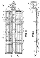
- FIGURE 10 is a top view, with portions cut away for clarity of illustration, of an exemplary assembly according to the invention;
- FIGURE 11 is a side view of the assembly of FIGURE 10;
- FIGURE 12 is an end view of an exemplary sheet dispensing apparatus according to the invention;
- FIGURE 13 is a side view of the apparatus of FIGURE 12;
- FIGURE 14 is a top perspective schematic view illustrating a potential end configuration of the sheet material associated with the apparatus of FIGURES 12 and 13;
- FIGURE 15 is a side schematic view illustrating a manner of dispensing of sheet material according to the invention; and
- FIGURE 16 is a side schematic view of an alternative form of apparatus to that illustrated in FIGURE 15.
- An
exemplary assembly 10 according to the present invention includes at least first andsecond fingers 11, 12, and when utilized for loading or unloading a 12m (40 foot) container, third andfourth fingers second fingers 11, 12 havefirst ends second ends fourth fingers first ends second ends air bearings 24 on the bottom thereof. - Preferably seven
conventional air bearings 24 are provided associated with each finger, each finger being between about 5.7 and 6m (19 and 20 feet) long. The air bearings may be obtained commercially from Air Float Corporation of Decatur, Illinois, or others. Each bearing has a lift capability of about 3628 kg (8,000 pounds). Air under pressure is supplied to the bearings at about 1,1 bar (16 psi) and discharged at about 0,273 bar (4 psi) (a low pressure system) and the air flow is typically about 0,266 m³/s (16 cubic feet per minute) per bearing (although it can be as low as 0,133 m³/s (8 ft. ³/min.) per bearing and still function). If desired, check valves may be incorporated in the bearings in order to provide greater stability for maneuverability and shifting loads. - Each finger 11-14 also has associated therewith, on the top surface thereof, at least one load bar, and preferably a pair of
inflatable load bars 26. The load bars are of inflatable, wear-resistant material. The free ends of the load bars 26 are inserted into slots in the vertical faces of the fingers 11-14, as illustrated at 26′ in FIGURE 5. - A central tubular portion is provided for each of the fingers 11-14 to supply air through the fingers to the
air bladders 24. The supply of air to the bearings may be provided by perforations (not shown) in the bottom of the central tubular portions communicating with each of the bearings using a conventional short pipe nipple (not shown) for each bladder. The central tubular portions for the fingers 11-14 are illustrated byreference numerals manifold 33 is connected to the first ends 15, 16 of thefingers 11, 12. - Operatively connected to the
structural manifold element 33 is a commercially available powered hand truck (also known as a tractor) 34. Preferably thehand truck 34 includes aninflatable bladder 35, which is utilized to facilitate transfer of some of the load from thefingers 11, 12 to the hand truck; ahandle 36 which includes controls for the hand truck thereon; and asteerable wheel 37. Asupport 38 rigidly attached to themember 33 connects theelement 33 to thehand truck 34, as does alink 38′. - Also mounted on the
element 33 are means for supplying air under pressure to the load bars 26, such means being schematically represented byreference numeral 39 in FIGURE 1, and shown in detail in FIGURES 6 and 7. - One exemplary manner in which each of the
fingers 11, 12 may be interconnected to theelement 33 is illustrated schematically in FIGURE 3 (for the element 11). A flange 41, having a pair of bolt receiving openings therein, extends downwardly from the end of theelement 33, and cooperates with aportion 42 of the finger 11, theportion 42 also having a pair of openings therein for receipt ofbolts 43 or like fasteners. Another set of flanges and fasteners is provided on the opposite side of thefirst end 15 of the finger 11. When the finger 11 is connected to theelement 33, theair port 44 associated with theelement 33 supplies air to the interior of thetubular element 28. - FIGURE 4 illustrates an exemplary interconnection between aligned fingers, in this case between the first and
third fingers 11, 13. The centraltubular air passageways resilient material gaskets 46, 47 (e g., of rubber), and metal (e.g., steel)ring 48.Gaskets portions portions metal ring 48 is sandwiched between thegaskets fingers 11, 13 are held together by the sets ofbolts 49 illustrated in FIGURE 4 at opposite sides thereof, thebolts 49 cooperating with openings (not shown) in theportions 49′ of thefingers 11, 13. - FIGURE 5 illustrates an end termination of the
fingers finger 13 being illustrated. Aplate 50 having the same approximate configuration as the circumference of the tubular passageway of theportion 30 fits over and blocks the passageway in theportion 30 with agasket 51 between the plate and thefinger 13.Bolts 52 or the like hold theplate 50 in place on theelement 13. - FIGURES 6 and 7 illustrate the various structures utilized to supply air to both the manifold 33 (ultimately supplied to the tubular portions 28-31 of the fingers 11-14, respectively), and also for supplying air to the load bars 26 for each of the fingers. The air-
ports tubular portions connection 55 supplying air to themanifold 33. - The following elements supply the air to the
bearings 24 associated with the fingers 11-13: The line (hose) 56 is connected to a source of compressed air at about 6,89 bar (100 psi) at the loading dock. Preferably quick connect/disconnect couplings 57 are provided for connection of theair hose 56 to thestructure 39. Air passes throughcoupling 57 to the main on/off valve 58, which is preferably a hand operated ball valve. The air then passes through T-connection 59 topressure regulator 60 for the air bearings (providing about a 1,1 bar (16 psi) maximum). Theregulator 60 is connected to T-connection 61 which in turn is connected to the load on/off 31,75 mm (1 1/4 inch) hand operatedball valve 62, which in turn is connected to the adjustable load flow hand operatedgate valve 63, and then to theconnection 55. Also connected toconnection 55 is the one inch hand operatedglobe valve 64, T-connection 65, quick connect/disconnect couplings 66, andline 67 which is the exhaust air line from thetractor 34. The other connection of the T-connection 65 is connected up to T-connection 68 and to relief valve 69 (preferably set at 20 psi maximum). - Air is also supplied from
hose 56 to the load bars 26. Connector 59 is also connected to T-connection 70, which in turn is connected toregulator 71, hand-operated 3-way valve 72, andmanifolds manifolds hoses 76 are connected to the load bars for the finger 11, thehoses 75 ultimately are connected to the load bars for thefinger 13, thehoses 78 are connected to the load bars for thefinger 12, and thehoses 77 are ultimately connected to the load bars for thefinger 14. - The T-
connector 70 is also connected throughquick disconnect couplings 79 to the line 80 for supplying air to thetractor 34. - FIGURE 8 illustrates the manner in which a hose is connected to a
load bar 26, in this case for the first finger 11. Thehose 76 passes from the manifold 73 through an opening in the finger to the bottom of the finger, as illustrated in FIGURE 8. Disposed in the interior of theload bar 26 is anut 81 which receives the threadedend 83 of an L-shapedconnector 82, theconnector 82end 84 being connected to thehose 76. - FIGURE 4 also illustrated the manner in which air is supplied to the load bars 26 associated with the third and fourth connectors, in this case for the
third connector 13. Thehoses 75 are provided withcouplings 86 at the ends thereof, and thosecouplings 86 cooperate withmating couplings 88 associated withhose sections 87 mounted on thefinger 13 and passing from the top to the bottom thereof (the connection of thehose sections 87 to the load bars 26 associated therewith being the same as illustrated for thehose section 76 in FIGURE 8). - An
exemplary assembly 10 according to the invention having been described, an exemplary method according to the invention, which utilizes theassembly 10, will now be described, with reference in particular to FIGURE 9. The method may comprise or consist of the recited steps, which preferably are practiced sequentially as set forth. - The
air hose 56 is connected to thestructure 39 by theelements 57, the main valve 58 and the load on/offvalve 62 are opened, and theload flow valve 63 is adjusted to provide the desired flow to themanifold 33. Air flowing intomanifold 33 and then throughair ports tubular elements bearings 24 associated with thefingers 11, 13. Using thehand truck 34, a single operator then moves thefingers 11, 13 simultaneously (being connected by the combined structural cross-member/manifold 33) so that they are inserted beneath thepallet 96, between thespacers 97 thereof, thepallet 96 adapted to be loaded into or unloaded from the longdistance transport container 95. - In order to most easily accommodate the fingers 11, 13 (which--when the
air bearings 24 are inflated--are about 4 inches high), thespacers 97 are preferably about 5 inches high. - Once the
fingers 11, 13 of theassembly 10 are completely beneath the pallet 96 (which may be multiple pallets disposed end-to-end), the manually operated three-way valve 72 is operated to supply air under pressure to themanifolds fingers 11, 13. The inflation of the load bars 26 causes thepallet 96 to be lifted off of the horizontal surface on which it is disposed. Then thehand truck 34 may be operated to move thepallet 96 into or out of thecontainer 95. Because of a construction of theassembly 10, only 2 inches of clearance are necessary between the pallet 96 (with goods thereon) and the top of thecontainer 95, whereas about 6 inches of clearance is necessary if the loading/unloading is done with a conventional fork lift. - In view of the provision of the
steerable wheel 37 on thehand truck 34, theassembly 10 may be moved laterally, with thepallet 96 supported thereby, to facilitate direct transfer of thepallet 96 from thecontainer 95 to a truck, train car, or the like that is at the loading dock. - Where a 40 foot container is to be loaded/unloaded instead of 20 foot container, the third and
fourth fingers second fingers 11, 12, and the steps set forth above performed as indicated, the assembly in this case supporting the pallet (or pallets) which completely fill a container that is 40 feet long. - If the surface which the
assembly 10 is to traverse is less even than desired, 4 mil flexibleplastic sheeting 98, or the like, may be laid over acontainer 95 bottom, a sheet metal bridge between thecontainer 95 and theloading dock 99, and/or other portions of the pathway to be traversed, to provide a non-porous smooth surface for the air casters to move over. This is preferably done as illustrated in FIGURES 10-16. - In FIGURES 10-16 an apparatus is provided for automatically dispensing sheet material beneath the fingers 11 through 14 so that they traverse as smooth a surface as possible during movement of a load thereby. The basic components of the apparatus for automatically dispensing sheet material are illustrated generally by
reference numerals - With particular reference to FIGURE 15, the
apparatus 140 is desirably mounted on the end of one or more fingers (e.g. onfingers deck surface 144.Plastic sheet material 146 is coiled on theapparatus 140. One form that the free end of theplastic sheet material 146 may take is illustrated in FIGURE 14, in which thesheet material 146 is wrapped around abar 148 and means are provided defining anopening 150 for receipt of thestructure 142. - The specific type of
sheet material 146 is not particularly critical. Sheeting 146 may be any sheet material which is flexible and may be readily dispensed and taken up, yet can provide a smooth surface over which the air bearings can move, and does not tear easily. One suitable sheet material is plastic, but others include rubber and metal. Reinforced plastic sheet material, such as ribbed nylon, is especially desirable. - While a
metal bar 148 and asemi-circular opening 150 are illustrated in FIGURE 14, other structures can be provided for engaging theapparatus 142. For example a grommeted hole may be provided at the end of thesheet material 146 - As seen most clearly in FIGURE 12,
sheet material 146 preferably is disposed betweenflanges 152 on ashaft 153, being coiled around the shaft. A groove, such as a groove having a l/8 inch width and 1/4 inch depth, may extend along the length of theshaft 153 to receive the blind end of thesheet material 146 therein, thereby connecting it to theshaft 153. Alternate arrangements for connecting thematerial 146 to theshaft 153 also may be provided. - The
apparatus 140 also comprises ameans 155 for applying tension to thesheeting 146 as it is dispensed and taken up. As illustrated in the drawings thetension applying means 155 comprises an air driven motor which is connected bygears shaft 153. A lubricatingassembly 159 may be mounted next to themotor 155.Motor 155 can be driven by the same air source as the bearings 124 or load bars 126. All of the components heretofore described preferably are mounted on aframe 161 having forward extendingarm portions 162, with means defining anopening 163 in eacharm 162 for receipt of theshaft 153, as seen most clearly in FIGURE 13. Theshaft 153 is thus rotatable with respect to theframe 161, with a constant force being applied to theshaft 153 by themotor 155, throughgears motor 155 would apply force to theshaft 153 so that there was a substantially constant tension of about 10 lbs. per square inch on thesheeting 146. - FIGURE 15 illustrates one
particular structure 142 for engaging the free end of thesheeting 146. In this embodiment ahook 166, pivotally mounted at 167 within a recess 171 in thedeck 144, is provided. As the finger 113 moves in the direction ofarrow 165 in FIGURE 6, thehook 66 will pass through theopening 50 and engage thebar 48. As movement of thefinger 13 continues, thehook 66 will be pivoted downwardly (leftmost position in FIGURE 6) until thebar 48 engages thedeck 44, straddling therecess 71. If desired, thepivot point 167 may be mounted by alever 168 to a shaft 149, to which spring tension or the like may be applied, to supply further tension to thesheeting 146. - An alternative configuration is illustrated in FIGURE 16 where functionally comparable structures are illustrated by the same reference numeral as in FIGURE 15 only with a "2" instead of a "1". In FIGURE 16, a
permanent magnet 266 is mounted within therecess 271 indeck 244, and is adapted to operatively engage the metal bar 248 (or other magnetizable, or magnetic, material at the free end of the sheeting 246), to hold thesheeting 246 as it is dispensed beneath thefingers 13, etc - In either the FIGURES 15 or 16 situations, as the
finger 13 ultimately moves back after loading, or unloading, a container (i.e. moves in a direction opposite to thedirection 165 in FIGURE 15), thesheeting 146 will automatically be taken up by themotor 155 on theshaft 153, and will automatically disengage from thehook 166 ormagnet 266 once its end of travel is reached. - It will be seen that where a common loading dock area is provided for loading and unloading transport containers, it is a simple matter to provide a recess 171 in the
deck 144 along the desired path of movement of the fingers 11 through 14, and thus easily automatically let out and take up thesheeting 146 to provide a smooth surface covering thedeck 144, over which the air bearings 124 move. - While the invention has been herein shown and described in what is presently conceived to be a practical and preferred embodiment thereof, it will be apparent that many modifications may be made within the scope of the invention. For example, in some environments it may be possible to mount the sheeting so that it is on the deck and the engaging structure is mounted on the fingers. A wide variety of other modifications are also possible, thus the invention is to be accorded the broadest interpretation of the appended claims so as encompass all equivalent structures and methods.
Claims (8)
- An assembly for moving a heavy load out of or into an overseas transport container, comprising:
first and second substantially identical fingers (11, 12) of relatively rigid material, each having first and second ends (17, 18), the height of said fingers being such that they may be inserted underneath a pallet (96) to effect lifting of the pallet;
at least one inflatable load bar (26) extending along the length of the top of each of said finger;
a structural cross-member (33) holding said first and second fingers together at said first ends thereof, so that they are spaced laterally from each other and extend substantially parallel to each other from said structural cross-member;
means (39) for supplying air under pressure to said load bars, said means mounted in operative association with said structural cross-member; and
a powered hand truck (34) mounted to said structural cross-member having a handle (36) and a driven wheel (37) steered by said handle for effecting horizontal movement of the assembly;
a plurality of air bearings (24) disposed along the length of the bottom of each of said fingers (11, 12), and each air bearing (24) operatively connected to a source (56) of air under pressure associated with its respective finger; and
a manifold (33) for supplying air under pressure to both said fingers (11, 12) for inflating the air bearings (24) of said fingers simultaneaously. - An assembly as recited in claim 1 further characterized in that said manifold (33) is a first manifold, and further characterized by a second manifold mounted on said structural cross-member, said second manifold (73, 74) comprising said means for supplying air to said load bars (26) of both said first and second fingers (11, 12).
- An assembly as recited in claim 2 further characterized in that said second manifold (73, 74) is connected to each said load bar by means comprising a length of hose (75-78) extending from said second manifold and extending to the bottom of the finger with which the load bar is associated; and a fitting (82) extending into the interior of the load bar adjacent said first end of said finger; said fitting connected to said hose; a nut (81) inside said inflatable load bar for holding said fitting in place with respect to said load bar
- An assembly as recited in claim 2 further characterized by a central rigid tubular portion (28, 30) of each of said fingers connected to said first manifold for supplying air from said first manifold to said bearings.
- An assembly as recited in claim 1 further characterized by third and fourth fingers (13, 14) laterally spaced from each other substantially identical to said first and second fingers, each having a first and second end (21, 22); and means (46-49) for connecting said third and fourth fingers to said first and second fingers, respectively, so that said third finger is an air-tight extension of said first finger with said first end of said third finger connected to the second end of said first finger, and said fourth finger is an air-tight extension of said second finger, with the first end of said fourth finger connected to the second end of said second finger.
- A method of loading or unloading an overseas transport container about 6m (20 feet) long with goods mounted on a pallet, the pallet with goods completely effectively filling the container, utilizing an assembly for moving heavy load as recited in any of claims 1 to 5, said method
comprising the steps of: (a) inflating the air bearings; (b) moving fingers underneath the pallet by manipulating the handle of the hand truck; (c) inflating the load bars to lift the pallet off of a horizontal surface on which it is resting; (d) moving the pallet linearly into, or out of, a transport container with the pallet vertically supported only by the air inflating the bladders and load bars; (e) deflating the load bars; and (f) removing the fingers, at the same time, from underneath the pallet; characterized in that steps (a) and (f) are practiced by moving the fingers simultaneously and together beneath the pallet and out from the pallet. - A method as recited in claim 6 characterized by the further step of automatically laying down a sheet of flexible sheet material (146) over the ground area to be traversed by the air bearings during the practice of steps (b) and (f) to facilitate movement therealong.
- A method as recited in claim 6 characterized by the further steps of connecting third and fourth fingers (13, 14), substantially identical to the first and second fingers, to the first and second fingers, respectively, so that the length of each of the first and third fingers combined, and the second fourth fingers combined, is approximately 12m (40 feet); and then repeating steps (a) through (f) for a 40 foot container.
Applications Claiming Priority (4)
| Application Number | Priority Date | Filing Date | Title |
|---|---|---|---|
| US42815 | 1987-04-27 | ||
| US07/042,815 US5129778A (en) | 1987-04-27 | 1987-04-27 | Container loading and unloading |
| US07/168,407 US4883140A (en) | 1987-04-27 | 1988-03-15 | Sheet material dispensing for air bearing structures |
| US168407 | 1998-10-08 |
Publications (3)
| Publication Number | Publication Date |
|---|---|
| EP0288914A2 EP0288914A2 (en) | 1988-11-02 |
| EP0288914A3 EP0288914A3 (en) | 1989-05-03 |
| EP0288914B1 true EP0288914B1 (en) | 1992-01-29 |
Family
ID=26719657
Family Applications (1)
| Application Number | Title | Priority Date | Filing Date |
|---|---|---|---|
| EP88106434A Expired - Lifetime EP0288914B1 (en) | 1987-04-27 | 1988-04-22 | Method and assembly for container loading and unloading |
Country Status (3)
| Country | Link |
|---|---|
| US (1) | US4883140A (en) |
| EP (1) | EP0288914B1 (en) |
| DE (1) | DE3868123D1 (en) |
Families Citing this family (1)
| Publication number | Priority date | Publication date | Assignee | Title |
|---|---|---|---|---|
| GB2291032A (en) * | 1994-06-01 | 1996-01-17 | Thornycroft Giles & Co Ltd | Load transportation |
Family Cites Families (7)
| Publication number | Priority date | Publication date | Assignee | Title |
|---|---|---|---|---|
| US2393655A (en) * | 1944-03-20 | 1946-01-29 | Robert B Robeck | Barricade traversing device for motor vehicles |
| US3108804A (en) * | 1961-05-05 | 1963-10-29 | Arthur W Wagner | Apparatus for covering outdoor athletic fields |
| JPS5237419Y2 (en) * | 1973-02-22 | 1977-08-25 | ||
| US3913854A (en) * | 1974-05-02 | 1975-10-21 | Phillips Petroleum Co | Tensioned unrolling device for fabric rolls |
| LU78224A1 (en) * | 1977-10-03 | 1979-06-01 | Eisgruber A | eOERDERWAGEN |
| US4440253A (en) * | 1981-07-06 | 1984-04-03 | Bertil Pernum | Crawler-type transport apparatus |
| US4705229A (en) * | 1983-10-17 | 1987-11-10 | Mounque Barazone | Compact apparatus for laying paving fabric |
-
1988
- 1988-03-15 US US07/168,407 patent/US4883140A/en not_active Expired - Fee Related
- 1988-04-22 DE DE8888106434T patent/DE3868123D1/en not_active Expired - Lifetime
- 1988-04-22 EP EP88106434A patent/EP0288914B1/en not_active Expired - Lifetime
Non-Patent Citations (1)
| Title |
|---|
| Bulletin d'Informations de la SICOS; "Pour une meilleure circulation", no. 28 (FR, juillet 1982), page 4 * |
Also Published As
| Publication number | Publication date |
|---|---|
| EP0288914A3 (en) | 1989-05-03 |
| US4883140A (en) | 1989-11-28 |
| EP0288914A2 (en) | 1988-11-02 |
| DE3868123D1 (en) | 1992-03-12 |
Similar Documents
| Publication | Publication Date | Title |
|---|---|---|
| US4240773A (en) | Roll handling apparatus | |
| US4684311A (en) | Load transporting apparatus | |
| AU687941B2 (en) | Container handling device | |
| CA2191013C (en) | Transportation and installation device for heavy pipes | |
| EP2173648A2 (en) | Cargo loader | |
| US4203697A (en) | Transfer apparatus for palletized loads | |
| US4533055A (en) | Storage rack for drilling tubulars | |
| WO2001007289A1 (en) | Container handling apparatus or cradle | |
| US6846144B2 (en) | Self-propelled load-bearing movement apparatus | |
| US5597282A (en) | Method and apparatus for unstacking and unloading a stacked load from one level to another level | |
| US5129778A (en) | Container loading and unloading | |
| WO2007106735A2 (en) | Apparatus for lifting and transporting a container | |
| US3887061A (en) | Portable modular materials distribution system | |
| US8226124B2 (en) | Mobile fluid storage tank with vertically adjustable hitch and rear support wheels | |
| US5378104A (en) | Apparatus for lifting a large roll of paper | |
| US20040093713A1 (en) | Method of an apparatus for assembling an aircraft wheel or brake component on an axle of an undercarriage | |
| US3825093A (en) | Modular air cushion transporting system | |
| EP0288914A2 (en) | Method and assembly for container loading and unloading | |
| US2932527A (en) | Wheeled conveyor for transportation containers | |
| US4718640A (en) | Apparatus for container handling | |
| US6460827B1 (en) | Pneumatic lift and movement system for shelving | |
| WO2005049461A1 (en) | Apparatus for carrying article, method of carrying article out from transportation container by using the apparatus, and method of carrying article into transportation container by using the apparatus | |
| US20070029170A1 (en) | Rolling conveyor support | |
| US20080029346A1 (en) | Go-between container transfer and system | |
| JP2740895B2 (en) | Method of unloading heavy work from transport container and loading heavy work into transport container |
Legal Events
| Date | Code | Title | Description |
|---|---|---|---|
| PUAI | Public reference made under article 153(3) epc to a published international application that has entered the european phase |
Free format text: ORIGINAL CODE: 0009012 |
|
| AK | Designated contracting states |
Kind code of ref document: A2 Designated state(s): BE DE ES FR GB GR IT NL SE |
|
| PUAL | Search report despatched |
Free format text: ORIGINAL CODE: 0009013 |
|
| AK | Designated contracting states |
Kind code of ref document: A3 Designated state(s): BE DE ES FR GB GR IT NL SE |
|
| RHK1 | Main classification (correction) |
Ipc: B65G 67/02 |
|
| 17P | Request for examination filed |
Effective date: 19891004 |
|
| 17Q | First examination report despatched |
Effective date: 19900904 |
|
| GRAA | (expected) grant |
Free format text: ORIGINAL CODE: 0009210 |
|
| AK | Designated contracting states |
Kind code of ref document: B1 Designated state(s): BE DE ES FR GB GR IT NL SE |
|
| PG25 | Lapsed in a contracting state [announced via postgrant information from national office to epo] |
Ref country code: SE Effective date: 19920129 Ref country code: NL Effective date: 19920129 Ref country code: BE Effective date: 19920129 Ref country code: IT Free format text: LAPSE BECAUSE OF FAILURE TO SUBMIT A TRANSLATION OF THE DESCRIPTION OR TO PAY THE FEE WITHIN THE PRE;WARNING: LAPSES OF ITALIAN PATENTS WITH EFFECTIVE DATE BEFORE 2007 MAY HAVE OCCURRED AT ANY TIME BEFORE 2007. THE CORRECT EFFECTIVE DATE MAY BE DIFFERENT FROM THE ONE RECORDED.SCRIBED TIME-LIMIT Effective date: 19920129 Ref country code: ES Free format text: THE PATENT HAS BEEN ANNULLED BY A DECISION OF A NATIONAL AUTHORITY Effective date: 19920129 Ref country code: GR Free format text: LAPSE BECAUSE OF FAILURE TO SUBMIT A TRANSLATION OF THE DESCRIPTION OR TO PAY THE FEE WITHIN THE PRESCRIBED TIME-LIMIT Effective date: 19920129 |
|
| REF | Corresponds to: |
Ref document number: 3868123 Country of ref document: DE Date of ref document: 19920312 |
|
| PG25 | Lapsed in a contracting state [announced via postgrant information from national office to epo] |
Ref country code: GB Effective date: 19920429 |
|
| EN | Fr: translation not filed | ||
| PG25 | Lapsed in a contracting state [announced via postgrant information from national office to epo] |
Ref country code: FR Effective date: 19920619 |
|
| NLV1 | Nl: lapsed or annulled due to failure to fulfill the requirements of art. 29p and 29m of the patents act | ||
| PLBE | No opposition filed within time limit |
Free format text: ORIGINAL CODE: 0009261 |
|
| STAA | Information on the status of an ep patent application or granted ep patent |
Free format text: STATUS: NO OPPOSITION FILED WITHIN TIME LIMIT |
|
| GBPC | Gb: european patent ceased through non-payment of renewal fee | ||
| 26N | No opposition filed | ||
| REG | Reference to a national code |
Ref country code: FR Ref legal event code: ST |
|
| PGFP | Annual fee paid to national office [announced via postgrant information from national office to epo] |
Ref country code: DE Payment date: 19930506 Year of fee payment: 6 |
|
| PG25 | Lapsed in a contracting state [announced via postgrant information from national office to epo] |
Ref country code: DE Effective date: 19950103 |