EP0287741A1 - Process for varying speech speed and device for implementing said process - Google Patents
Process for varying speech speed and device for implementing said process Download PDFInfo
- Publication number
- EP0287741A1 EP0287741A1 EP87430010A EP87430010A EP0287741A1 EP 0287741 A1 EP0287741 A1 EP 0287741A1 EP 87430010 A EP87430010 A EP 87430010A EP 87430010 A EP87430010 A EP 87430010A EP 0287741 A1 EP0287741 A1 EP 0287741A1
- Authority
- EP
- European Patent Office
- Prior art keywords
- sub
- band
- signal
- phase
- speech
- Prior art date
- Legal status (The legal status is an assumption and is not a legal conclusion. Google has not performed a legal analysis and makes no representation as to the accuracy of the status listed.)
- Granted
Links
Images


Classifications
-
- G—PHYSICS
- G10—MUSICAL INSTRUMENTS; ACOUSTICS
- G10L—SPEECH ANALYSIS OR SYNTHESIS; SPEECH RECOGNITION; SPEECH OR VOICE PROCESSING; SPEECH OR AUDIO CODING OR DECODING
- G10L21/00—Processing of the speech or voice signal to produce another audible or non-audible signal, e.g. visual or tactile, in order to modify its quality or its intelligibility
- G10L21/04—Time compression or expansion
Landscapes
- Engineering & Computer Science (AREA)
- Human Computer Interaction (AREA)
- Quality & Reliability (AREA)
- Signal Processing (AREA)
- Health & Medical Sciences (AREA)
- Audiology, Speech & Language Pathology (AREA)
- Computational Linguistics (AREA)
- Physics & Mathematics (AREA)
- Acoustics & Sound (AREA)
- Multimedia (AREA)
- Transmission Systems Not Characterized By The Medium Used For Transmission (AREA)
- Ultra Sonic Daignosis Equipment (AREA)
- Magnetic Resonance Imaging Apparatus (AREA)
- Compression, Expansion, Code Conversion, And Decoders (AREA)
Abstract
Description
- This invention deals with voice processing and more particularly with methods for speeding-up or slowing down speech messages.
- Sped speech, or variable speed speech usually denotes a means to either slow-down or speed-up recorded speech messages without over altering their quality.
- Such means are of great interest in voice processing systems, such as voice store and forward systems wherein voice signals are stored for being played-back later on at a varied speed. They are particularly useful to operators looking for a specific portion of speech within a recorded message, by enabling speeding-up the play back to locate rapidly the portion looked for, and then slowing down the process while listening said portion of message. It should be noted that while the speed varying might conventionally be achieved with mechanical means whenever speech is stored in its analog form on moving memories; but this would distort the signal (pitch) and in addition it would not apply to digital systems wherein speech is processed digitally.
- A sophisticated method for implementing sped speech has been proposed by M.R. Portnoff in IEEE Trans. on Acoust., Speech and Signal Processing, Vol. ASSP 24 No 3, pp. 243-248, June 1976 (Implementation of the digital phase vocoder using the Fast Fourier Transform). This method is based on adaptive measurement of the pitch period and insertion or deletion of speech samples on a pitch period basis. This technique requires the accurate estimation of the pitch period, which is both complex and expansive to achieve, more particularly in applications involving telephone signals wherein the low part of the frequency bandwitch (0-300 Hz) including the pitch has been removed.
- This invention proposes a technique for performing speech speed variation without needing pitch measurement while providing a quality level equivalent to the one provided by methods based on pitch consideration. The proposed method presents a low complexity once associated with sub-band coding, but can be considered separately. It can also apply to Voice-Excited Predictive Coding (VEPC).
- An object of this invention is thus to provide a process for digitally speeding-up or slowing-down a speech message, said process involving splitting at least a portion of the considered speech signal bandwidth into several narrow subbands, converting each sub-band contents into phase/magnitude representation and then performing sample deletion/insertion over each sub-band phase and magnitude data, according to the desired speech rate variation, then recombining the sub-band contents into speech.
- The foregoing and other objects, features and advantages of the invention will be apparent from the following more particular description of a preferred embodiment of the invention, as illustrated in the accompanying drawings.
-
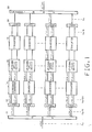
- Figure 1 is a block diagram of one embodiment of this invention.
- Figure 2-4 are circuits to be used in the device of figure 1.
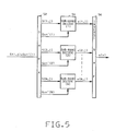
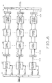
- Figures 5-7 are block diagrams showing the application of this invention in a system wherein the original voice signal was coded using split-band techniques.
- This invention will be described for a digitally encoded voice signal assuming said encoding did not involve band splitting. It will then be applied to split band coders.
- Figure 1 shows a preferred embodiment of this invention. The speech signal s(n) representing the contents of a limited bandwidth of the voice signal to be processed, sampled at a given frequency (e.g. Nyquist) fs and digitally encoded is first split into N sub-bands by a bank of quadrature mirror filters (QMF) 10. The QMFʹs are filters known in the voice processing art and presented by A. Croisier, D. Esteban and C. Galand, at the 1976 International Conference on Information Sciences and Systems, at Patras, in a presentation entitled "Perfect Channel splitting by use of interpolation/decimation/tree decomposition techniques". The
device 10 provides N subband signals x(1,n); x(2,n); ....; x(N,n). The sub-band resolution must be high enough to catch the harmonic structure of the speech signal in all cases. Since the human pitch frequency can be as low as 80 Hz, a bank of filters providing N=40 sub-bands would be theoretically necessary to cover the telephone bandwidth (300-3400Hz). - Each subband signal is down sampled to a rate fs/N to keep a constant overall sample rate throughout the system. The sub-band signals x(i,n), with i=1, 2, ... N are fed into complex QMF filters (CQMF)12, and processed to extract therefrom the analytical signal consisting in an in-phase component u(i,n), and a quadrature component v(i,n), which are down sampled by two by dropping every other sample. The complex QMF filtering means will be described further by referring to figure 2.
- In each sub-band, the in-phase u(n) and quadrature v(n) components of the signal are then processed by a cartesian to polar
coordinates converter circuit 14 to derive therefrom a digital magnitude signal M(i,n) and a digital phase signal P(i,n) according to:
M(i,n) = (u²(i,n) + v²(i,n))1/2 (1)
speeding device 16 to be described further.Device 16 provides speed varyed couples of output signals Mʹ(i,n) and Pʹ(i,n) which are then recombined back to cartesian coordinates in adevice 18 providing a couple of in-phase and quadrature components according to:
uʹ(i,n) = Mʹ(i,n). cos Pʹ(i,n) (3)
vʹ(i,n) = Mʹ(i,n). sin Pʹ(i,n) (4)
Pʹ(i,n) being the phase information of the speed varied sub-band signal, to be determined as indicated further on (see figure 4). - In each sub-band, the uʹ and vʹ components represent the original sub-band signal, at the new rate, and are then recombined by (inverse) complex quadrature mirror filters (CQMF) 20. The resulting sub-band signals xʹ(i,n) are processed by an inverse QMF bank of
filters 22 to generate the speed varied speech signal sʹ(n). - Represented in figure 2 is a circuit for performing the operations of direct and inverse complex QMF's i.e.,
devices - The complex QMF (CQMF) was described by H.J. Nussbaumer and C. Galand at the EUSIPCO 83 conference, in a presentation "Parallel filter banks using complex quadrature mirror filters". Using the CQMF techniques, the two quadrature signals u(n) and v(n) are derived from the real sub-band signal x(n) by:

X(Z), U(Z), V(Z) are the Z=transform of x(n), u(n) and v(n), and H(Z) is the Z transform of a low-pass M-tap CQMF filter, with M even. Assuming the linear distortion due to the CQMF filter (ripple) be neglected, then the magnitude M(n) and phase P(n) of x(n) can be evaluated from u(n) and v(n) according to equations (1) and (2). - In order to insure a perfect reconstruction, the filter H(Z) must have a 3dB attenuation at frequency fs/4N, and the magnitude H(w) of the Fourier transform must be such that:

w = 2π.f - In practice, the filter H(Z) must be sufficiently sharp to eliminate the cross-modulation terms appearing when computing (1) and (2).
- For further details on design rules for these filters, one may refer to the article, "Magnitude-Phase coding of base-band speech signals" presented by C. Galand, H. Nussbaumer and J. Perrini at the IEEE International Conference on Acoustics, Speech and Signal Processing (ICASSP), held in Tokyo in 1986. Assuming now that the input speech signal x(n) has a harmonic structure and the respective sub-bands are rather narrow, with no aliasing, then each subband would contain a single harmonic. If the input signal is stationary, then the magnitude M(n) of each sub-band signal is constant and its phase P(n) varies linearly.
- In fact, the speech signal is not stationary, but the above conditions are closely approximated. As a result, the magnitude M(n) of the signal in each sub-band is varying slowly (at the syllabic rate), and the phase P(n) of this same signal is varying almost linearly.
- Once converted into phase/magnitude data, the sub-band signals M(i, n) and P(i,n), are processed into an up/
down device 16. Prior to describing this device, let's consider pratical situations for up/down speeding ratios. In audio distribution systems, this ratio will be selected in the 0.5 to 2 range. In other words the speech can be played at least at half its original speed and at most at twice said original speed. Practically, this range is not covered continuously, but through a few discrete values in the interval (.5-2). The choices are not really critical and the ratios for speeding up and slowing down the speech have been selected to be according to ratios K/K-1 and K/K+ 1 respectively with the original speed being normalized to 1.
- Figure 3 shows a schematic representation of the up/down operations to be performed over the magnitude data M(n) within each sub-band.For speeding up the magnitude signals are simply decimated by the appropriate ratio. For example, assuming the desired speech speed should be doubled (K/K-1 = 2/1). Then, every second sample of the magnitude signal is just dropped. For a ratio of 1.5 , every third sample of the magnitude signal is suppressed. Generally speaking, for a K/K1 ratio, every Kth sample of the magnitude signal M(n) is dropped. The operation on each block of K input samples M(n), n=1, ...K, is described by the following relations.
Mʹ(n) = M(n) n=1,...,K-1 (8)
where M(n), n=1,...,K-1 represents the output sequence of magnitude samples. - For slowing-down process, a similar operation is performed. For a K/
K+ 1 ratio, every Kth sample of the magnitude signal is duplicated. The operation on each block of K input samples M(n), n=1,..,K is described by the following relations.
Mʹ(n) = M(n) n=1,...,K (9)
Mʹ(K+1) = M(K)
Where Mʹ(n), n=1,...,K+1 represents the output sequence of magnitude samples. - For example, a 2 to 1 slowing down operation will result in a repetition of every M(n) sample to derive Mʹ(n).
- Represented in figure 4 is the circuit used within the up/down
speed device 16 for processing the phase signal P(n) within each sub-band. The speed change over the phase signal is implemented as follows. The phase samples P(n) are first pre-processed to derive a difference signal or phase increment sequence D(n) using a one sample delay cell (T) 40 and a subtractor (42), both fed with the P(n) sequence.
D(n) = P(n) - P(n-1) (10)
For a K/K-1 ratio speeding up, every Kth sample of the difference signal D(n) is dropped. The operation on each block of K input samples D(n), n=1,...,K, is made intodevice 44 according to:
Dʹ(n) = D(n) n=1,...,K-1 (11)
Where Dʹ(n), n=1,...,K-1 represents the difference output sequence. - For a slowing down process, a similar operation is performed. Slowing down by a ratio K/
K+ 1 is achieved through a duplication indevice 46 of every Kth sample of the difference signal D(n). The operation on each block of K input samples D(n), n=1,...,K, is described by the following equations:
Dʹ(n) = D(n) n=1,...,K
Dʹ(K+1) = D(K)
where Dʹ(n), n=1,...,K+1 represents the output sequence of the difference samples once slowed down. - In both, slowing-down and speeding-up instances the recovery of the phase samples from the difference samples is implemented, using a one sample period delay cell (T) and an adder (+), according to the following relation.
Pʹ(n) = Pʹ(n-1) + Dʹ(n).
- Also in both slowing-down and speeding-up instances the ratio might be different from K/K+1 or K/K-1 by deleting or inserting more than one sample per block of length K.The above described process enables implementing a sped speech system independently of any consideration about the source of the speech signal. It can thus be used in combination with any digital coder. But, obviously, it suits particularly well to sub-band coders (SBC) wherein harmonic analysis by QMF filers is already available. These coders have heen extensively described in the litterature, but one may refer to the following publications or patents herein incorporated by reference:
"Voice excited predictive coder (VEPC), implementation on high-performance signal processor" by C. Galand, C. Couturier, G. Platel and R. Vermot-Gauchy, IBM Journal of Research and Development Volume 29,Number 2, March 1985
European Patent 0 002 998 (US counterpart 4216354)
French Patent 77 13225 (US counterpart 4142071). - In the sub-band coder as disclosed above the input signal bandwidth has been split into several sub-bands. Then the content of each sub-band has been coded with quantizers dynamically adjusted to the respective sub-band contents. In other words, the bits (or levels) quantizing resources for the overall original bandwidth are dynamically shared among the sub-bands. In addition, assuming the coding method involved using the Block Companded PCM techniques (BCPCM), then, the coding was performed on a blocks basis. In other words, the coderʹs quantizing parameters were adjusted for predetermined length consecutive blocks of samples. For each block of samples the coder provided and multiplexed in its output: sub-band quantized samples S(i,j), i=1, ...,N being the sub-band index, and j the time index within a block; one quantizer step Q; and, N terms nʹ(i) each representing the number of bits dynamically assigned for quantizing the considered sub-band contents. In practice, it should be noted that other types of data than Q and nʹ(i) might be used as long as these quantizer step data enable recovering the step to be assigned to the inverse quantizing operations to be performed to convert the quantized samples back into digitally encoded samples.
- Represented in figure 5 is a block diagram of the synthesizer to be used to recombine the S(i,j), Q and nʹ(i) data into the original voice signal s(n). Basically, the synthesizer input signal is first demultiplexed in 52 into its components before being sub-band decoded into an
inverse quantizer 54. For that purpose, each SUB-BAND DECODER is fed with a block of quantized samples S(i,j) and controlled by Q and nʹ(i). Each decoder or inverse quantizer provides a set of digital coded samples x(i,j), which are fed into an inverse QMF filter providing a recombined speech signal s(n). - This type of coder/decoder structure suits particularly well to this invention as shown in figure 6 representing a block diagram of the sped speech of this invention applied to the split band decoder represented in figure 5. The sub-bands decoded signals x(i,j), sampled at fs/N are directly fed into Complex. QMF filters 64 operating as the CQMF filters 12 of figure 1 do. In other words there is no need for the QMF filter bank of figure 1, since perfect band splitting has already been performed in the coding process and completed with the demultiplexing in 60 and sub-band decoding in 62.
- The remaining parts (64, 66, 68, 70, 72 and 74) are respectively made according to the circuits (12, 14, 16, 18, 20 and 22) of figure 1. Finally, the output signal sʹ(n) is a speeded-up or slowed/down speech signal as required. Basically, thus, applying this invention to the split band coded signal saves two banks of filters, i.e.
QMF 10 andinverse QMF 22. - The proposed sped speech technique may also be combined with the Voice Excited Predictive Coding (VEPC) process, since this type of coder involves using sub-band coding on the low frequency bandwidth (base band) of the voice signal. In addition, the bandwidth of each sub-band is narrow enough to ensure a proper operation of the sped speech device.
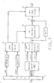
- Represented in figure 7 is a block diagram showing the insertion of the device of this invention within a VEPC synthesizer made according to device of figure 8 of the above cited European reference 0 002 998 or to device of figure 3 of the cited IBM Journal of Research and Development. The base-band sub-band signals S(i,j) provided by an input demultiplexer DMPX(71) are decoded into a set of signals x(i,n), which are fed into a speed-up/slow down device (70) made according to this invention (see figure 1). The speeded-up/slowed-down base-band signal xʹ(n) is then used to regenerate the high frequency bandwidth (HB) modulated by the decoded (DECODED1) high frequency energy (ENERG) in 72 as disclosed in the cited references. Then high band signal and low band signal delayed to compensate for the transit time within 72 are added together in 74. The adder output drives then a
vocal tract filter 76 the coefficients of which are adjusted with the decoded COEF data, and the output of which is the reconstructed speech signal sʹ(n). - The speech descriptors, i.e. high frequency energy (ENERG) and PARCOR coefficients (COEF) are up-dated on a block basis and linearly interpolated. The sped speech operation concerning these parameters are achieved into a
device 78 by adjusting the linear interpolation step size to the new block length. - While the invention has been particularly shown and described with reference to preferred embodiments applying two specific split band coding techniques, it will be understood by those skilled in the art that it may apply to other voice coding/decoding schemes.
Claims (8)
- splitting at least a portion of the speech frequency bandwidth into N consecutive narrow sub-bands;
- processing each sub-band contents to derive therefrom phase samples and magnitude samples representative of the sub-band signal contents expressed in polar coordinates;
- slowing-down or speeding-up said sub-band signal contents by repeating phase and magnitude samples or deleting samples therefrom at a rate depending upon the desired slowing-down or speeding-up rate respectively;
- recombing each sub-band phase/magnitude data into a sub-band signal; and
- recombing the sub-band signals into a speech, whereby said recombining speech is a slowed-down/speeded-up version of the processed speech signal.
- deriving from each sub-band signal contents an analytical signal consisting of an in-phase component and a quadrature component through use of complex quadrature mirror filtering techniques;
- sampling-down said analytical signal by dropping every other sample from said in-phase and quadrature components; and,
- converting said sampled down analytical signal into its phase/magnitude components.
- First bank of quadrature mirror filters (QMF) for splitting a limited bandwidth of said speech signal into N narrow sub-bands;
- down sampling means, connected to said QMF bank for down sampling each sub-band signal at a rate fs/N;
- complex quadrature mirror filtering (CQMF) means connected to said first bank of QMF's for converting each sub-band contents into an analytical signal represented by in-phase and quadrature components;
- 2nd down sampling means connected to said CQMF for down sampling said in-phase and quadrature components to fs/2N;
- coordinate converting means connected to said second down sampling means for converting said analytical signal into a magnitude M(i,n) and a phase components P(i, n), with i=1,...,N being the sub-band index and n being the time index;
- up-down speed means connected to said coordinate converting means for deleting/inserting samples at a rate depending upon the desired speech rate variation whereby Mʹ(i,n) and Pʹ(i,n)data are generated;
- coordinate converting means connected to said up/down speed means for converting said Mʹ(i,n) and Pʹ(i,n) into rate converted analytical data uʹ(i,n) and vʹ(i,n);
- means for up sampling said uʹ(i,n), vʹ(i,n) to fs/N;
- inverse complex QMF filters connected to said up sampling means;
- up sampling means for up sampling said CQMF filters to a rate fs; and,
- an inverse QMF filter bank connected to said up sampling means and providing a slowed down or speeded up speech signal sʹ(n).
- means for speeding up the speech signal at a rate K/K-1, K being a predetermined integer value, including, for each sub-band:
- means for converting the M(n) sequence into a speeded-up Mʹ(n) by deleting every Kth M(n) sample;
- means for generating a phase increment sequence D(n) according to
D(n) = P(n) - P(n-1)
- means for converting the D(n) sequence into Dʹ(n) by deleting every Kth sample from D(n); and,
- means for generating a speeded-up phase sequence Pʹ(n) with:
Pʹ(n) = Pʹ(n-1) + Dʹ(n)
- means for slowing-down the speech signal at a rate K/K+1, including for each sub-band:
- means for converting the M(n) sequence into a slowed-down sequence Mʹ(n) by repeating every Kth M(n) sample;
- means for converting the D(n) sequence into Dʹ(n) by duplicating every Kth sample.
Priority Applications (4)
| Application Number | Priority Date | Filing Date | Title |
|---|---|---|---|
| EP87430010A EP0287741B1 (en) | 1987-04-22 | 1987-04-22 | Process for varying speech speed and device for implementing said process |
| DE87430010T DE3785189T2 (en) | 1987-04-22 | 1987-04-22 | Method and device for changing speech speed. |
| JP63064756A JPS63273898A (en) | 1987-04-22 | 1988-03-19 | Digital method and apparatus for slowing down and speeding up voice signal |
| US07/423,732 US5073938A (en) | 1987-04-22 | 1989-10-17 | Process for varying speech speed and device for implementing said process |
Applications Claiming Priority (1)
| Application Number | Priority Date | Filing Date | Title |
|---|---|---|---|
| EP87430010A EP0287741B1 (en) | 1987-04-22 | 1987-04-22 | Process for varying speech speed and device for implementing said process |
Publications (2)
| Publication Number | Publication Date |
|---|---|
| EP0287741A1 true EP0287741A1 (en) | 1988-10-26 |
| EP0287741B1 EP0287741B1 (en) | 1993-03-31 |
Family
ID=8198300
Family Applications (1)
| Application Number | Title | Priority Date | Filing Date |
|---|---|---|---|
| EP87430010A Expired - Lifetime EP0287741B1 (en) | 1987-04-22 | 1987-04-22 | Process for varying speech speed and device for implementing said process |
Country Status (4)
| Country | Link |
|---|---|
| US (1) | US5073938A (en) |
| EP (1) | EP0287741B1 (en) |
| JP (1) | JPS63273898A (en) |
| DE (1) | DE3785189T2 (en) |
Cited By (2)
| Publication number | Priority date | Publication date | Assignee | Title |
|---|---|---|---|---|
| EP2360688A1 (en) * | 2009-10-21 | 2011-08-24 | Panasonic Corporation | Sound signal processing apparatus, sound encoding apparatus and sound decoding apparatus |
| US8611547B2 (en) | 2006-07-04 | 2013-12-17 | Electronics And Telecommunications Research Institute | Apparatus and method for restoring multi-channel audio signal using HE-AAC decoder and MPEG surround decoder |
Families Citing this family (14)
| Publication number | Priority date | Publication date | Assignee | Title |
|---|---|---|---|---|
| US5392044A (en) * | 1993-03-08 | 1995-02-21 | Motorola, Inc. | Method and apparatus for digitizing a wide frequency bandwidth signal |
| US5285499A (en) * | 1993-04-27 | 1994-02-08 | Signal Science, Inc. | Ultrasonic frequency expansion processor |
| US5787387A (en) * | 1994-07-11 | 1998-07-28 | Voxware, Inc. | Harmonic adaptive speech coding method and system |
| US5920842A (en) * | 1994-10-12 | 1999-07-06 | Pixel Instruments | Signal synchronization |
| JP3328080B2 (en) * | 1994-11-22 | 2002-09-24 | 沖電気工業株式会社 | Code-excited linear predictive decoder |
| US5727119A (en) * | 1995-03-27 | 1998-03-10 | Dolby Laboratories Licensing Corporation | Method and apparatus for efficient implementation of single-sideband filter banks providing accurate measures of spectral magnitude and phase |
| US5839099A (en) * | 1996-06-11 | 1998-11-17 | Guvolt, Inc. | Signal conditioning apparatus |
| JP2955247B2 (en) * | 1997-03-14 | 1999-10-04 | 日本放送協会 | Speech speed conversion method and apparatus |
| FR2768545B1 (en) * | 1997-09-18 | 2000-07-13 | Matra Communication | METHOD FOR CONDITIONING A DIGITAL SPOKEN SIGNAL |
| US6266643B1 (en) | 1999-03-03 | 2001-07-24 | Kenneth Canfield | Speeding up audio without changing pitch by comparing dominant frequencies |
| SE9903223L (en) * | 1999-09-09 | 2001-05-08 | Ericsson Telefon Ab L M | Method and apparatus of telecommunication systems |
| US6868377B1 (en) * | 1999-11-23 | 2005-03-15 | Creative Technology Ltd. | Multiband phase-vocoder for the modification of audio or speech signals |
| US20030187663A1 (en) * | 2002-03-28 | 2003-10-02 | Truman Michael Mead | Broadband frequency translation for high frequency regeneration |
| JP5243620B2 (en) | 2010-06-09 | 2013-07-24 | パナソニック株式会社 | Band extension method, band extension apparatus, program, integrated circuit, and audio decoding apparatus |
Citations (1)
| Publication number | Priority date | Publication date | Assignee | Title |
|---|---|---|---|---|
| EP0070948A1 (en) * | 1981-07-28 | 1983-02-09 | International Business Machines Corporation | Voice coding method and arrangment for carrying out said method |
Family Cites Families (11)
| Publication number | Priority date | Publication date | Assignee | Title |
|---|---|---|---|---|
| US3462555A (en) * | 1966-03-23 | 1969-08-19 | Bell Telephone Labor Inc | Reduction of distortion in speech signal time compression systems |
| US3816664A (en) * | 1971-09-28 | 1974-06-11 | R Koch | Signal compression and expansion apparatus with means for preserving or varying pitch |
| JPS5146808A (en) * | 1974-10-18 | 1976-04-21 | Matsushita Electric Ind Co Ltd | |
| FR2389277A1 (en) * | 1977-04-29 | 1978-11-24 | Ibm France | QUANTIFICATION PROCESS WITH DYNAMIC ALLOCATION OF THE AVAILABLE BIT RATE, AND DEVICE FOR IMPLEMENTING THE SAID PROCESS |
| FR2412987A1 (en) * | 1977-12-23 | 1979-07-20 | Ibm France | PROCESS FOR COMPRESSION OF DATA RELATING TO THE VOICE SIGNAL AND DEVICE IMPLEMENTING THIS PROCEDURE |
| JPS55147697A (en) * | 1979-05-07 | 1980-11-17 | Sharp Kk | Sound synthesizer |
| US4464784A (en) * | 1981-04-30 | 1984-08-07 | Eventide Clockworks, Inc. | Pitch changer with glitch minimizer |
| US4700391A (en) * | 1983-06-03 | 1987-10-13 | The Variable Speech Control Company ("Vsc") | Method and apparatus for pitch controlled voice signal processing |
| JPS606998A (en) * | 1983-06-24 | 1985-01-14 | ソニー株式会社 | Signal processor |
| US4709390A (en) * | 1984-05-04 | 1987-11-24 | American Telephone And Telegraph Company, At&T Bell Laboratories | Speech message code modifying arrangement |
| US4852168A (en) * | 1986-11-18 | 1989-07-25 | Sprague Richard P | Compression of stored waveforms for artificial speech |
-
1987
- 1987-04-22 DE DE87430010T patent/DE3785189T2/en not_active Expired - Lifetime
- 1987-04-22 EP EP87430010A patent/EP0287741B1/en not_active Expired - Lifetime
-
1988
- 1988-03-19 JP JP63064756A patent/JPS63273898A/en active Pending
-
1989
- 1989-10-17 US US07/423,732 patent/US5073938A/en not_active Expired - Lifetime
Patent Citations (1)
| Publication number | Priority date | Publication date | Assignee | Title |
|---|---|---|---|---|
| EP0070948A1 (en) * | 1981-07-28 | 1983-02-09 | International Business Machines Corporation | Voice coding method and arrangment for carrying out said method |
Non-Patent Citations (2)
| Title |
|---|
| IEEE TRANSACTIONS ON ACOUSTICS, SPEECH, AND SIGNAL PROCESSING, vol. ASSP-29, no. 3, June 1981, pages 374-390, IEEE, New York, US; M.R. PORTNOFF: "Time-scale modification of speech based on short-time Fourier analysis" * |
| IEEE TRANSACTIONS ON ACOUSTICS, SPEECH, AND SIGNAL PROCESSING, vol. ASSP-34, no. 6, December 1986, pages 1449-1464, IEEE, New York, US; T.F. QUATIERI et al.: "Speech transformations based on a sinusoidal representation" * |
Cited By (6)
| Publication number | Priority date | Publication date | Assignee | Title |
|---|---|---|---|---|
| US8611547B2 (en) | 2006-07-04 | 2013-12-17 | Electronics And Telecommunications Research Institute | Apparatus and method for restoring multi-channel audio signal using HE-AAC decoder and MPEG surround decoder |
| US8848926B2 (en) | 2006-07-04 | 2014-09-30 | Electronics And Telecommunications Research Institute | Apparatus and method for restoring multi-channel audio signal using HE-AAC decoder and MPEG surround decoder |
| EP2360688A1 (en) * | 2009-10-21 | 2011-08-24 | Panasonic Corporation | Sound signal processing apparatus, sound encoding apparatus and sound decoding apparatus |
| EP2360688A4 (en) * | 2009-10-21 | 2013-09-04 | Panasonic Corp | Sound signal processing apparatus, sound encoding apparatus and sound decoding apparatus |
| EP2704143A3 (en) * | 2009-10-21 | 2014-04-02 | Panasonic Corporation | Audio signal processing apparatus, audio coding apparatus, and audio decoding apparatus |
| US9026236B2 (en) | 2009-10-21 | 2015-05-05 | Panasonic Intellectual Property Corporation Of America | Audio signal processing apparatus, audio coding apparatus, and audio decoding apparatus |
Also Published As
| Publication number | Publication date |
|---|---|
| JPS63273898A (en) | 1988-11-10 |
| EP0287741B1 (en) | 1993-03-31 |
| US5073938A (en) | 1991-12-17 |
| DE3785189T2 (en) | 1993-10-07 |
| DE3785189D1 (en) | 1993-05-06 |
Similar Documents
| Publication | Publication Date | Title |
|---|---|---|
| EP0287741B1 (en) | Process for varying speech speed and device for implementing said process | |
| US4569075A (en) | Method of coding voice signals and device using said method | |
| EP0002998B1 (en) | Method and system for speech data compression | |
| US4677671A (en) | Method and device for coding a voice signal | |
| US5067158A (en) | Linear predictive residual representation via non-iterative spectral reconstruction | |
| US6680972B1 (en) | Source coding enhancement using spectral-band replication | |
| US4631746A (en) | Compression and expansion of digitized voice signals | |
| US5357594A (en) | Encoding and decoding using specially designed pairs of analysis and synthesis windows | |
| US6173255B1 (en) | Synchronized overlap add voice processing using windows and one bit correlators | |
| JPS6326947B2 (en) | ||
| Crochiere et al. | Real-time speech coding | |
| JPH06503186A (en) | Speech synthesis method | |
| RU2256293C2 (en) | Improving initial coding using duplicating band | |
| JP3065343B2 (en) | Signal transmission method | |
| US3071652A (en) | Time domain vocoder | |
| US5392231A (en) | Waveform prediction method for acoustic signal and coding/decoding apparatus therefor | |
| JPS63201700A (en) | Band pass division encoding system for voice and musical sound | |
| CA2053133C (en) | Method for coding and decoding a sampled analog signal having a repetitive nature and a device for coding and decoding by said method | |
| KR100727276B1 (en) | Transmission system with improved encoder and decoder | |
| Galand et al. | Voice-excited predictive coder (VEPC) implementation on a high-performance signal processor | |
| JPH0784595A (en) | Band dividing and encoding device for speech and musical sound | |
| JP3292228B2 (en) | Signal encoding device and signal decoding device | |
| JPH07273656A (en) | Method and device for processing signal | |
| Foo et al. | Hybrid frequency-domain coding of speech signals | |
| Davie | Channel vocoder based on ccd discrete-Fourier-transform processors |
Legal Events
| Date | Code | Title | Description |
|---|---|---|---|
| PUAI | Public reference made under article 153(3) epc to a published international application that has entered the european phase |
Free format text: ORIGINAL CODE: 0009012 |
|
| AK | Designated contracting states |
Kind code of ref document: A1 Designated state(s): DE FR GB |
|
| 17P | Request for examination filed |
Effective date: 19890222 |
|
| 17Q | First examination report despatched |
Effective date: 19910131 |
|
| GRAA | (expected) grant |
Free format text: ORIGINAL CODE: 0009210 |
|
| AK | Designated contracting states |
Kind code of ref document: B1 Designated state(s): DE FR GB |
|
| REF | Corresponds to: |
Ref document number: 3785189 Country of ref document: DE Date of ref document: 19930506 |
|
| ET | Fr: translation filed | ||
| PLBE | No opposition filed within time limit |
Free format text: ORIGINAL CODE: 0009261 |
|
| STAA | Information on the status of an ep patent application or granted ep patent |
Free format text: STATUS: NO OPPOSITION FILED WITHIN TIME LIMIT |
|
| 26N | No opposition filed | ||
| REG | Reference to a national code |
Ref country code: GB Ref legal event code: IF02 |
|
| PGFP | Annual fee paid to national office [announced via postgrant information from national office to epo] |
Ref country code: DE Payment date: 20030331 Year of fee payment: 17 |
|
| PGFP | Annual fee paid to national office [announced via postgrant information from national office to epo] |
Ref country code: GB Payment date: 20030401 Year of fee payment: 17 |
|
| PGFP | Annual fee paid to national office [announced via postgrant information from national office to epo] |
Ref country code: FR Payment date: 20030424 Year of fee payment: 17 |
|
| PG25 | Lapsed in a contracting state [announced via postgrant information from national office to epo] |
Ref country code: GB Free format text: LAPSE BECAUSE OF NON-PAYMENT OF DUE FEES Effective date: 20040422 |
|
| PG25 | Lapsed in a contracting state [announced via postgrant information from national office to epo] |
Ref country code: DE Free format text: LAPSE BECAUSE OF NON-PAYMENT OF DUE FEES Effective date: 20041103 |
|
| GBPC | Gb: european patent ceased through non-payment of renewal fee |
Effective date: 20040422 |
|
| PG25 | Lapsed in a contracting state [announced via postgrant information from national office to epo] |
Ref country code: FR Free format text: LAPSE BECAUSE OF NON-PAYMENT OF DUE FEES Effective date: 20041231 |
|
| REG | Reference to a national code |
Ref country code: FR Ref legal event code: ST |