EP0287706A2 - Hydrogen discharge lamp and method of manufacturing it - Google Patents
Hydrogen discharge lamp and method of manufacturing it Download PDFInfo
- Publication number
- EP0287706A2 EP0287706A2 EP87114255A EP87114255A EP0287706A2 EP 0287706 A2 EP0287706 A2 EP 0287706A2 EP 87114255 A EP87114255 A EP 87114255A EP 87114255 A EP87114255 A EP 87114255A EP 0287706 A2 EP0287706 A2 EP 0287706A2
- Authority
- EP
- European Patent Office
- Prior art keywords
- bulb
- lamp
- borosilicate glass
- boron oxide
- lamp bulb
- Prior art date
- Legal status (The legal status is an assumption and is not a legal conclusion. Google has not performed a legal analysis and makes no representation as to the accuracy of the status listed.)
- Granted
Links
Images

Classifications
-
- C—CHEMISTRY; METALLURGY
- C03—GLASS; MINERAL OR SLAG WOOL
- C03C—CHEMICAL COMPOSITION OF GLASSES, GLAZES OR VITREOUS ENAMELS; SURFACE TREATMENT OF GLASS; SURFACE TREATMENT OF FIBRES OR FILAMENTS MADE FROM GLASS, MINERALS OR SLAGS; JOINING GLASS TO GLASS OR OTHER MATERIALS
- C03C17/00—Surface treatment of glass, not in the form of fibres or filaments, by coating
- C03C17/02—Surface treatment of glass, not in the form of fibres or filaments, by coating with glass
-
- H—ELECTRICITY
- H01—ELECTRIC ELEMENTS
- H01J—ELECTRIC DISCHARGE TUBES OR DISCHARGE LAMPS
- H01J61/00—Gas-discharge or vapour-discharge lamps
- H01J61/02—Details
- H01J61/30—Vessels; Containers
- H01J61/35—Vessels; Containers provided with coatings on the walls thereof; Selection of materials for the coatings
-
- H—ELECTRICITY
- H01—ELECTRIC ELEMENTS
- H01J—ELECTRIC DISCHARGE TUBES OR DISCHARGE LAMPS
- H01J9/00—Apparatus or processes specially adapted for the manufacture, installation, removal, maintenance of electric discharge tubes, discharge lamps, or parts thereof; Recovery of material from discharge tubes or lamps
- H01J9/24—Manufacture or joining of vessels, leading-in conductors or bases
- H01J9/245—Manufacture or joining of vessels, leading-in conductors or bases specially adapted for gas discharge tubes or lamps
- H01J9/247—Manufacture or joining of vessels, leading-in conductors or bases specially adapted for gas discharge tubes or lamps specially adapted for gas-discharge lamps
Definitions
- the invention relates to a hydrogen discharge lamp with a lamp bulb, and electrodes arranged therein, which contains, at least in the emission area, an area which is permeable to UV light and has boron oxide, and a method for its production.
- hydrogen lamps is to be understood as meaning gas discharge lamps which are either filled with hydrogen or deuterium or with a mixture of the two.
- hydrogen lamps experience a loss in intensity over the course of their operating time, which is essentially due to a decrease in the bulb transmission.
- This decrease in transmission is caused in particular by emitter material originating from the cathode, such as barium, strontium, calcium, which is deposited on the inner wall of the bulb. The material diffuses into the quartz glass and reacts with it. This greatly reduces the high UV radiation transmission of the pure quartz glass, in particular in the 250 nm wavelength range.
- the lifespan of a hydrogen lamp is generally defined as the period of time that it can be operated until its intensity at a predetermined wavelength has decreased by at least 50% compared to its initial intensity.
- the lifespan at a wavelength of 230 nm for lamps with conventional cathode construction is approximately 750 hours.
- a discharge lamp filled with hydrogen or deuterium is known from US Pat. No. 3,956,655, in which borosilicate glass is used as the bulb material, a lifespan that is longer by a factor of 2 in the wavelength range in question being achieved. This longer lifespan is due to the chemically higher resistance of borosilicate glass to alkaline earth than is the case with quartz glass.
- the lower UV permeability of borosilicate glass compared to quartz glass must be compensated for here by a thinner wall. This is done either by ring-shaped thin drawing or tubular blowing out of the glass bulb.
- the object of the invention is to improve the service life of hydrogen lamps which have a lamp bulb made of quartz glass; the transmission of the lamp bulb should only be reduced by less than 10% in the wavelength range of ⁇ 300 nm.
- a borosilicate layer is provided at least in one area on the inside of the lamp bulb facing the discharge.
- the inside of the lamp bulb facing the discharge contains boron oxide that has diffused in at least in one region to a thickness of 10 ⁇ m.
- a layer of a suspension containing at least boron oxide is applied to the inside of the lamp bulb at least in one area, the layer is baked after a drying process and the surface facing the discharge is glazed to form borosilicate glass; the baking temperature is advantageously chosen so high that the borosilicate glass is formed during the baking process.
- the higher transmission in the wavelength range below 250 nm proves to be advantageous with the same wall thickness compared to known lamps; the subject of the invention is also applicable to lamps with pistons made of synthetic quartz glass, the field of use of which also extends to wavelengths below 200 nm.
- the lamp according to the invention in an environment at a higher temperature, in particular in high-temperature applications such as those e.g. may be required in exhaust systems, test systems or chimneys.
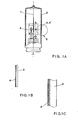
- FIGS. 1A, 1B, 1C and 2 show a broken longitudinal section through the lamp;
- FIG. 1B shows a longitudinal section through the layer structure of the piston wall at the level of the electrode arrangement;
- FIG. 1C shows a longitudinal section through the bulb wall with a diffused borosilicate glass layer.
- Figure 2 shows a transmission diagram for the various arrangements.
- the electrode system consisting of anode and cathode is located in the housing 3 in the area of the axis 1 of the cylindrical lamp bulb 2, a screen made of high-melting metal, such as molybdenum, being arranged between the electrodes designed as a coil in order to achieve the highest possible radiance .
- the opening angle of the emitted radiation is, for example, in the range of 30-40 °.
- the layer 4 according to the invention is located on the inside of the lamp bulb 2 made of quartz glass. Its layer thickness lies in a range between 50 nm and 10 ⁇ . To make it easier to see, this extremely thin layer 4 is shown in the figure by broken lines.
- FIGS. 1B and 1C each show longitudinal sections of the piston wall in the area of the dashed circle 5.
- FIG. 1B shows a longitudinal section of the wall of the lamp according to the invention at the level of the electrode system; In this figure, layer 4 is shown by hatching for a better overview.
- boron oxide can also be applied to the inside of the lamp bulb by sputtering or by thermal evaporation.
- a baking process is carried out after drying, through which the surface of the quartz glass layer is glazed to form borosilicate glass.
- FIG. 1C shows in longitudinal section a lamp bulb 2 which has a borosilicate surface 4 ⁇ on its inside, but which no longer represents an independent layer as in FIG. 1B. Rather, the quartz glass of the bulb and the borosilicate glass form a continuous structure, the inside having borosilicate glass as the surface; the borosilicate surface 4 ⁇ is symbolically represented by dots according to Figure 1C for a better overview.
- the inside of the quartz glass bulb is provided with a thin layer of a boron oxide suspension, which after a short drying, e.g. with a flame.
- a boron oxide suspension which after a short drying, e.g. with a flame.
- This borosilicate glass surface makes the inside of the bulb chemically resistant to the alkaline earths that are deposited during lamp operation. This results in a lower transmission decrease and thus a longer lifespan for the hydrogen lamp.
- Figure 2 shows the spectral transmission in percent for various piston materials in the ultraviolet range from 200 to 300 nm wavelength.
- Curve A shows the transmission of 1 mm thick borosilicate glass. It can be seen here that the transmission at 200 nm is just under 50%, while it increases with increasing wavelength and a transmittance of approximately 85% is already achieved in the region of 250 nm.
- Curve B shows the transmission of borosilicate glass with a thickness of 0.3 mm; due to the lower strength there is a considerably improved transmission, so that a transmission value of 74% is already achieved at 200 nm, the increase with increasing wavelength being small in relation to curve A. The transmission at a wavelength of 250 nm reaches a value of approx. 88%.
- Curve C shows the course of the transmission for 1 mm thick quartz glass. It can be seen here that a transmission value of approx. 82% is achieved even at a wavelength of 200 nm, while the transmission is approx. 90% in the wavelength range of 250 nm.
- the dash-dotted curve D shows the spectral transmission for 1 mm thick piston material which, according to FIG. 1c, contains boron oxide diffused on its inside. It can be seen here that the absorption is very low compared to pure quartz glass.
- the transmission values of curve D in the wavelength range from 200 to 260 nm are considerably higher than the values of curve A, which applies to borosilicate glass of the same thickness; With a deviation of at most 2%, the transmission values of curve D almost reach the transmission values of curve C.
Landscapes
- Chemical & Material Sciences (AREA)
- Engineering & Computer Science (AREA)
- Life Sciences & Earth Sciences (AREA)
- Chemical Kinetics & Catalysis (AREA)
- General Chemical & Material Sciences (AREA)
- Geochemistry & Mineralogy (AREA)
- Materials Engineering (AREA)
- Organic Chemistry (AREA)
- Manufacturing & Machinery (AREA)
- Vessels And Coating Films For Discharge Lamps (AREA)
- Discharge Lamp (AREA)
Abstract
Bei Wasserstoff-Entladungslampen mit einem Quarzglaskolben (2) und darin angeordneten Elektroden, die als Emittermaterial Mischoxide aus Barium, Kalzium oder Strontium aufweisen, schlägt sich Emittermaterial an der Kolbeninnenwand nieder und reduziert durch chemische Reaktion die hohe UV-Strahlungsdurchlässigkeit des reinen Quarzglases.In the case of hydrogen discharge lamps with a quartz glass bulb (2) and electrodes arranged therein, which have mixed oxides of barium, calcium or strontium as the emitter material, emitter material is deposited on the inside of the bulb and reduces the high UV radiation permeability of the pure quartz glass through chemical reaction.
Auf der der Entladung zugekehrten Innenseite (4) des Kolbens (2) ist Borosilikatglas vorgesehen. Borosilicate glass is provided on the inside (4) of the bulb (2) facing the discharge.
Description
Die Erfindung betrifft eine Wasserstoff-Entladungslampe mit einem Lampenkolben, und darin angeordneten Elektroden, der wenigstens im Emissionsbereich einen für UV-Licht durchlässigen Bereich, der Boroxid aufweist, enthält sowie ein Verfahren zu ihrer Herstellung.The invention relates to a hydrogen discharge lamp with a lamp bulb, and electrodes arranged therein, which contains, at least in the emission area, an area which is permeable to UV light and has boron oxide, and a method for its production.
Unter dem Begriff Wasserstofflampen sollen in vorliegender Erfindung Gasentladungslampen verstanden werden, die entweder mit Wasserstoff oder Deuterium oder mit einem Gemisch beider gefüllt sind.In the present invention, the term hydrogen lamps is to be understood as meaning gas discharge lamps which are either filled with hydrogen or deuterium or with a mixture of the two.
Im Vergleich zu ihrer Anfangsintensität erfahren Wasserstofflampen im Laufe ihrer Betriebszeit einen Intensitätsverlust, der im wesentlichen auf eine Abnahme der Kolbentransmission zurückzuführen ist. Diese Transmissionsabnahme wird hervorgerufen insbesondere durch von der Kathode stammendes Emittermaterial, wie beispielsweise Barium, Strontium, Kalzium, das sich an der Kolbeninnenwand niederschlägt. Das Material diffundiert in das Quarzglas hinein und reagiert mit diesem. Hierdurch wird die hohe UV-Strahlungsdurchlässigkeit des reinen Quarzglases, insbesondere im Wellenlängenbereich 250 nm, stark reduziert.Compared to their initial intensity, hydrogen lamps experience a loss in intensity over the course of their operating time, which is essentially due to a decrease in the bulb transmission. This decrease in transmission is caused in particular by emitter material originating from the cathode, such as barium, strontium, calcium, which is deposited on the inner wall of the bulb. The material diffuses into the quartz glass and reacts with it. This greatly reduces the high UV radiation transmission of the pure quartz glass, in particular in the 250 nm wavelength range.
Als Lebensdauer einer Wasserstofflampe wird im allgemeinen die Zeitdauer definiert, die sie betrieben werden kann, bis bei einer vorgegebenen Wellenlänge ihre Intensität um wenigstens 50 % gegenüber ihrer Anfangsintensität abgesunken ist. So beträgt die Lebensdauer bei einer Wellenlänge von 230 nm bei Lampen mit herkömmlicher Kathodenkonstruktion ca. 750 Stunden.The lifespan of a hydrogen lamp is generally defined as the period of time that it can be operated until its intensity at a predetermined wavelength has decreased by at least 50% compared to its initial intensity. The lifespan at a wavelength of 230 nm for lamps with conventional cathode construction is approximately 750 hours.
Aus der US-PS 3,956,655 ist eine mit Wasserstoff oder Deuterium gefüllte Entla- dungslampe bekannt, bei der Borosilikatglas als Kolbenmaterial verwendet wird, wobei eine um den Faktor 2 längere Lebensdauer im fraglichen Wellenlängen-Be- reich erzielt wird. Diese längere Lebensdauer beruht auf der chemisch gesehen höheren Resistenz von Borosilikatglas gegenüber Erdalkalien, als es bei Quarz- glas der Fall ist. Die gegenüber Quarzglas geringere UV-Durchlässigkeit des Borosilikatglases muß hier durch eine dünnere Wand kompensiert werden. Dies geschieht entweder durch ringförmiges Dünnziehen oder tubusförmiges Ausblasen des Glaskolbens.A discharge lamp filled with hydrogen or deuterium is known from US Pat. No. 3,956,655, in which borosilicate glass is used as the bulb material, a lifespan that is longer by a factor of 2 in the wavelength range in question being achieved. This longer lifespan is due to the chemically higher resistance of borosilicate glass to alkaline earth than is the case with quartz glass. The lower UV permeability of borosilicate glass compared to quartz glass must be compensated for here by a thinner wall. This is done either by ring-shaped thin drawing or tubular blowing out of the glass bulb.
Es ist hier ein zusätzlicher mechanischer Aufwand notwendig. Weiterhin besteht aufgrund der verringerten Wandstärke mit ca. 0,3 mm eine erhöhte Bruchgefahr.An additional mechanical effort is necessary here. Furthermore, there is an increased risk of breakage due to the reduced wall thickness of approx. 0.3 mm.
Die Erfindung stellt sich die Aufgabe, die Lebensdauer von Wasserstofflampen zu verbessern, die einen Lampenkolben aus Quarzglas aufweisen; dabei soll die Transmission des Lampenkolbens im Wellenlängenbereich von < 300 nm nur um weniger als 10 % reduziert werden.The object of the invention is to improve the service life of hydrogen lamps which have a lamp bulb made of quartz glass; the transmission of the lamp bulb should only be reduced by less than 10% in the wavelength range of <300 nm.
Die Aufgabe wird erfindungsgemäß durch die kennzeichnenden Merkmale des Anspruchs 1 gelöst.The object is achieved by the characterizing features of
In einer bevorzugten Ausführungsform des Gegenstandes der Erfindung ist auf der der Entladung zugekehrten Innenseite des Lampenkolbens wenigstens in einem Bereich eine Borosilikatschciht aufgebacht.In a preferred embodiment of the subject matter of the invention, a borosilicate layer is provided at least in one area on the inside of the lamp bulb facing the discharge.
Bei einer weiteren bevorzugten Ausführungsform des Gegenstandes der Erfindung enthält die der Entladung zugekehrte Innenseite des Lampenkolbens wenigstens in einem Bereich eindiffundiertes Boroxid bis zu einer Stärke von 10 µm.In a further preferred embodiment of the subject matter of the invention, the inside of the lamp bulb facing the discharge contains boron oxide that has diffused in at least in one region to a thickness of 10 μm.
In einem bevorzugten Verfahren zur Herstellung einer erfindungsgemäßen Wasserstofflampe wird auf die Innenseite des Lampenkolbens wenigstens in einem Bereich eine Schicht aus einer mindestens Boroxid enthaltenden Suspension aufgebracht, die Schicht nach einem Trockenvorgang eingebrannt und die der Entladung zugewandte Oberfläche unter Bildung von Borosilikatglas verglast; dabei wird vorteilhafterweise die Einbrenntemperatur so hoch gewählt, daß während des Einbrennvorganges das Borosilikatglas gebildet wird.In a preferred method for producing a hydrogen lamp according to the invention, a layer of a suspension containing at least boron oxide is applied to the inside of the lamp bulb at least in one area, the layer is baked after a drying process and the surface facing the discharge is glazed to form borosilicate glass; the baking temperature is advantageously chosen so high that the borosilicate glass is formed during the baking process.
Weitere vorteilhafte Ausgestaltungen des Gegenstandes der Erfindung sind den Unteransprüchen zu entnehmen.Further advantageous refinements of the subject matter of the invention can be found in the subclaims.
Als vorteilhaft erweist sich die bei gleicher Wandstärke gegenüber bekannten Lampen höhere Transmission im Wellenlängenbereich unterhalb 250 nm; der Gegenstand der Erfindung ist auch auf Lampen mit Kolben aus synthetischem Quarzglas anwendbar, deren Einsatzbereich sich auch auf Wellenlängen unterhalb 200 nm erstreckt.The higher transmission in the wavelength range below 250 nm proves to be advantageous with the same wall thickness compared to known lamps; the subject of the invention is also applicable to lamps with pistons made of synthetic quartz glass, the field of use of which also extends to wavelengths below 200 nm.
Weiterhin erweist es sich als vorteilhaft, die erfindungsgemäße Lampe in einem Umfeld höherer Temperatur einsetzen zu können, insbesondere bei Hochtemperatureinsätzen, wie sie z.B. in Abgassystemen, Testsystemen oder Schornsteinen erforderlich sein können.Furthermore, it proves to be advantageous to be able to use the lamp according to the invention in an environment at a higher temperature, in particular in high-temperature applications such as those e.g. may be required in exhaust systems, test systems or chimneys.
Im folgenden ist der Gegenstand der Erfindung anhand der Figuren 1A, 1B, 1C, und 2 näher erläutert. Figur 1A zeigt einen aufgebrochenen Längsschnitt durch die Lampe; Figur 1B zeigt einen Längsschnitt durch den Schichtenaufbau der Kolbenwand in Höhe der Elektrodenanordnung; Figur 1C zeigt einen Längsschnitt durch die Kolbenwand mit eindiffundierter Borosilikatglasschicht. Figur 2 zeigt ein Transmissionsdiagramm für die verschiedenen Anordnungen.The subject matter of the invention is explained in more detail below with reference to FIGS. 1A, 1B, 1C and 2. Figure 1A shows a broken longitudinal section through the lamp; FIG. 1B shows a longitudinal section through the layer structure of the piston wall at the level of the electrode arrangement; FIG. 1C shows a longitudinal section through the bulb wall with a diffused borosilicate glass layer. Figure 2 shows a transmission diagram for the various arrangements.
Gemäß Figur 1A befindet sich im Bereich der Achse 1 des zylindrischen Lampenkolbens 2 das aus Anode und Kathode bestehende Elektrodensystem im Gehäuse 3, wobei zur Erzielung einer möglichst hohen Strahldichte zwischen den als Wendel ausgeführten Elektroden eine Blende aus hochschmelzendem Metall, wie z.B. Molybdän, angeordnet ist. Der Öffnungswinkel der emittierten Strahlung liegt z.B. im Bereich von 30 - 40°.According to FIG. 1A, the electrode system consisting of anode and cathode is located in the
Auf der Innenseite des aus Quarzglas bestehenden Lampenkolbens 2 befindet sich die erfindungsgemäße Schicht 4. Ihre Schichtstärke liegt in einem Bereich zwischen 50 nm und 10 µ. Zur besseren Erkennbarkeit ist diese äußerst dünne Schicht 4 in der Figur durch gestrichelte Linien dargestellt. Die Figuren 1B und 1C stellen jeweils Längschnitte der Kolbenwand im Bereich des gestrichelten Kreises 5 dar.The
Figur 1B zeigt einen Längsschnitt der Wand der erfindungsgemäßen Lampe in Höhe des Elektrodensystems; in dieser Figur ist die Schicht 4 zwecks besserer Übersicht durch Schraffierung dargestellt.FIG. 1B shows a longitudinal section of the wall of the lamp according to the invention at the level of the electrode system; In this figure,
Es ist möglich, durch Tauchen in eine Lösung, wie z.B. Borsäure, die Innenseite des Lampenkolbens 2 zu beschichten, doch kann Boroxid auch durch Kathodenzerstäubung oder durch thermisches Aufdampfen auf die Innenseite des Lampenkolbens aufgebracht werden.It is possible to immerse in a solution such as e.g. Boric acid to coat the inside of the
Beim Aufbringen einer Boroxidsuspension durch Tauchen, Aufspritzen oder Auftragen wird nach Antrocknen ein Einbrennvorgang durchgeführt, durch den die Oberfläche der Quarzglasschicht unter Bildung von Borosilikatglas verglast wird.When a boron oxide suspension is applied by dipping, spraying or applying, a baking process is carried out after drying, through which the surface of the quartz glass layer is glazed to form borosilicate glass.
Durch Maskierung der Innenseite des Lampenkolbens 2 oder partielles Aufsprühen oder Auftragen der Suspension ist es auch möglich, nur den für den Durchtritt des Strahlenbündels vorgesehenen Teil der Innenseite des Lampenkolbens mit der erfindungsgemäßen Schicht zu versehen. Hierbei ist allerdings eine möglichst genaue Justierung der Strahlenaustrittsrichtung erforderlich.By masking the inside of the
Figur 1C zeigt im Längsschnitt einen Lampenkolben 2, der auf seiner Innenseite eine Borosilikatfläche 4ʹ aufweist, die jedoch keine eigenständige Schicht wie in Figur 1B mehr darstellt. Vielmehr bilden das Quarzglas des Kolbens und das Borosilikatglas eine durchgehende Struktur, wobei die Innenseite Borosilikatglas als Oberfläche aufweist; die Borosilikatfläche 4ʹ ist gemäß Figur 1C zwecks besserer Übersicht durch Punkte symbolisch dargestellt.FIG. 1C shows in longitudinal section a
Zur Herstellung wird die Innenseite des Quarzglaskolbens mit einer dünnen Schicht einer Boroxidsuspension versehen, die nach kurzem Antrocknen, z.B. mit einer Flamme, eingebrannt wird. Hierdurch wird eine Borosilikatglas-Oberfläche gebildet, die wegen ihrer geringen Stärke die Transmission des Quarzglases nicht nachteilig beeinflußt. Durch diese Borosilikatgals-Oberfläche wird die Innenseite des Kolbens chemisch resistent gegen die sich während des Lampenbetriebs niederschlagenden Erdalkalien. Hieraus resultiert eine geringere Transmissionsabnahme und somit eine längere Lebensdauer der Wasserstofflampe.For the production, the inside of the quartz glass bulb is provided with a thin layer of a boron oxide suspension, which after a short drying, e.g. with a flame. This forms a borosilicate glass surface which, because of its low thickness, does not adversely affect the transmission of the quartz glass. This borosilicate glass surface makes the inside of the bulb chemically resistant to the alkaline earths that are deposited during lamp operation. This results in a lower transmission decrease and thus a longer lifespan for the hydrogen lamp.
Figur 2 zeigt die spektrale Transmission in Prozent für verschiedene Kolbenmaterialien im Ultraviolett-Bereich von 200 bis 300 nm Wellenlänge. Dabei zeigt Kurve A die Transmission 1 mm starken Borosilikatglases. Hier ist erkennbar, daß die Transmission bei 200 nm knapp unter 50 % liegt, während sie mit zunehmender Wellenlänge steigt und im Bereich von 250 nm bereits ein Transmissionsgrad von ca. 85 % erzielt wird. Kurve B zeigt die Transmission von Borosilikatglas mit einer Stärke von 0,3 mm; aufgrund der geringeren Stärke liegt eine erheblich verbesserte Transmission vor, so daß bei 200 nm bereits ein Transmissionswert von 74 % erzielt wird, wobei der Anstieg mit zunehmender Wellenlänge im Verhältnis zur Kurve A gering ist. So erreicht die Transmission bei einer Wellenlänge von 250 nm Wert von ca. 88 %.Figure 2 shows the spectral transmission in percent for various piston materials in the ultraviolet range from 200 to 300 nm wavelength. Curve A shows the transmission of 1 mm thick borosilicate glass. It can be seen here that the transmission at 200 nm is just under 50%, while it increases with increasing wavelength and a transmittance of approximately 85% is already achieved in the region of 250 nm. Curve B shows the transmission of borosilicate glass with a thickness of 0.3 mm; due to the lower strength there is a considerably improved transmission, so that a transmission value of 74% is already achieved at 200 nm, the increase with increasing wavelength being small in relation to curve A. The transmission at a wavelength of 250 nm reaches a value of approx. 88%.
Kurve C zeigt den Verlauf der Transmission für 1 mm starkes Quarzglas. Hier ist erkennbar, daß bereits bei einer Wellenlänge von 200 nm ein Transmissionswert von ca. 82 % erzielt wird, während im Wellenlängenbereich von 250 nm die Transmission bei ca. 90 % liegt.Curve C shows the course of the transmission for 1 mm thick quartz glass. It can be seen here that a transmission value of approx. 82% is achieved even at a wavelength of 200 nm, while the transmission is approx. 90% in the wavelength range of 250 nm.
Die strichpunktierte Kurve D zeigt die spektrale Transmission für 1 mm starkes Kolbenmaterial, das gemäß Figur 1c auf seiner Innenseite eindiffundiertes Boroxid enthält. Hier ist erkannbar, daß die Absorption gegenüber reinem Quarzglas sehr gering ist. Die Transmissionswerte der Kurve D liegen im Wellenlängenbereich von 200 bis 260 nm erheblich über den Werten der für Borosilikatglas gleicher Stärke geltenden Kurve A; die Transmissionswerte der Kuve D erreichen mit einer Abweichung von höchstens 2 % nahezu die Transmissionswerte der Kurve C.The dash-dotted curve D shows the spectral transmission for 1 mm thick piston material which, according to FIG. 1c, contains boron oxide diffused on its inside. It can be seen here that the absorption is very low compared to pure quartz glass. The transmission values of curve D in the wavelength range from 200 to 260 nm are considerably higher than the values of curve A, which applies to borosilicate glass of the same thickness; With a deviation of at most 2%, the transmission values of curve D almost reach the transmission values of curve C.
Im Wellenlängenbereich von 270 bis 300 nm ist erkennbar, daß die Wirkung der Absorption mit zunehmender Wellenlänge nachläßt, wobei der Transmissionswert praktisch nur noch aus Reflexionsverlusten an den Grenzflächen resultiert.In the wavelength range from 270 to 300 nm it can be seen that the effect of the absorption diminishes with increasing wavelength, the transmission value practically only resulting from reflection losses at the interfaces.
Claims (7)
Applications Claiming Priority (2)
| Application Number | Priority Date | Filing Date | Title |
|---|---|---|---|
| DE19873713704 DE3713704A1 (en) | 1987-04-24 | 1987-04-24 | HYDROGEN DISCHARGE LAMP AND METHOD FOR THE PRODUCTION THEREOF |
| DE3713704 | 1987-04-24 |
Publications (3)
| Publication Number | Publication Date |
|---|---|
| EP0287706A2 true EP0287706A2 (en) | 1988-10-26 |
| EP0287706A3 EP0287706A3 (en) | 1990-09-12 |
| EP0287706B1 EP0287706B1 (en) | 1994-01-19 |
Family
ID=6326196
Family Applications (1)
| Application Number | Title | Priority Date | Filing Date |
|---|---|---|---|
| EP87114255A Expired - Lifetime EP0287706B1 (en) | 1987-04-24 | 1987-09-30 | Hydrogen discharge lamp and method of manufacturing it |
Country Status (3)
| Country | Link |
|---|---|
| EP (1) | EP0287706B1 (en) |
| JP (1) | JPS63274052A (en) |
| DE (2) | DE3713704A1 (en) |
Cited By (1)
| Publication number | Priority date | Publication date | Assignee | Title |
|---|---|---|---|---|
| WO1990009032A1 (en) * | 1989-01-25 | 1990-08-09 | Heraeus Instruments Gmbh | Deuterium lamp for spectral analysis devices |
Families Citing this family (2)
| Publication number | Priority date | Publication date | Assignee | Title |
|---|---|---|---|---|
| DE102006040613B3 (en) * | 2006-08-30 | 2007-11-29 | Heraeus Noblelight Gmbh | Translucent low pressure discharge hydrogen lamp for spectral analytical application, has metallic housing construction protecting discharge chamber in bulb filled with deuterium |
| DE102009014425B4 (en) | 2009-03-26 | 2011-02-03 | Heraeus Noblelight Gmbh | deuterium lamp |
Family Cites Families (10)
| Publication number | Priority date | Publication date | Assignee | Title |
|---|---|---|---|---|
| BE351245A (en) * | 1929-08-30 | |||
| US2030390A (en) * | 1929-08-30 | 1936-02-11 | Gen Electric | Glass |
| DE1042115B (en) * | 1955-11-26 | 1958-10-30 | Kern & Sprenger K G Dr | Water-cooled hydrogen lamp with quartz discharge vessel |
| US3390298A (en) * | 1965-03-31 | 1968-06-25 | Gen Electric | Electric discharge lamp envelope having molten inner surface at operating temperature |
| US3505553A (en) * | 1966-05-12 | 1970-04-07 | Philips Corp | Radio-interference-free low-pressure mercury-vapor lamp |
| JPS5039948A (en) * | 1973-08-15 | 1975-04-12 | ||
| US3956655A (en) * | 1974-12-23 | 1976-05-11 | Westinghouse Electric Corporation | Ultraviolet radiation source |
| US4016445A (en) * | 1975-11-28 | 1977-04-05 | Gte Sylvania Incorporated | Deuterium arc lamp |
| DE2906038A1 (en) * | 1979-02-16 | 1980-08-28 | Siemens Ag | LAMP PISTON |
| JPS61179052A (en) * | 1985-02-04 | 1986-08-11 | Hitachi Ltd | Hydrogen luminous tube |
-
1987
- 1987-04-24 DE DE19873713704 patent/DE3713704A1/en active Granted
- 1987-09-30 EP EP87114255A patent/EP0287706B1/en not_active Expired - Lifetime
- 1987-09-30 DE DE87114255T patent/DE3788870D1/en not_active Expired - Fee Related
- 1987-12-04 JP JP62306075A patent/JPS63274052A/en active Pending
Cited By (1)
| Publication number | Priority date | Publication date | Assignee | Title |
|---|---|---|---|---|
| WO1990009032A1 (en) * | 1989-01-25 | 1990-08-09 | Heraeus Instruments Gmbh | Deuterium lamp for spectral analysis devices |
Also Published As
| Publication number | Publication date |
|---|---|
| EP0287706A3 (en) | 1990-09-12 |
| DE3788870D1 (en) | 1994-03-03 |
| EP0287706B1 (en) | 1994-01-19 |
| DE3713704C2 (en) | 1990-03-29 |
| DE3713704A1 (en) | 1988-11-03 |
| JPS63274052A (en) | 1988-11-11 |
Similar Documents
| Publication | Publication Date | Title |
|---|---|---|
| DE69514710T2 (en) | Metal halide lamp | |
| DE2431128C2 (en) | High pressure mercury vapor lamp | |
| EP0706201A2 (en) | Mercury vapour lamp with short arc | |
| DE2908890C2 (en) | ||
| DE69903685T2 (en) | Fluorescent lamp with a protective layer consisting of spherical metal oxide particles and method for producing the same | |
| DE2951741A1 (en) | ELECTRODE FOR A DISCHARGE LAMP | |
| DE69117316T2 (en) | Fluorescent lamp and its manufacturing process | |
| DE69413439T2 (en) | Metal vapor discharge lamp | |
| DD289850A5 (en) | GEFAERTE ELECTRIC LAMP | |
| DE3876158T2 (en) | THIN FILM ELECTROLUMINESCENCE DEVICE. | |
| DE3246656C2 (en) | Fluorescent display tube | |
| DE1068380B (en) | ||
| EP0287706B1 (en) | Hydrogen discharge lamp and method of manufacturing it | |
| DE2418131C3 (en) | Fluorescent lamp with window | |
| DE68927166T2 (en) | Ultraviolet radiation protection tube | |
| DE69823623T2 (en) | Fluorescent Lamp | |
| EP0520248B1 (en) | Electric lamp | |
| DE3910431C2 (en) | ||
| DE3024438A1 (en) | LOW PRESSURE MERCURY STEAM DISCHARGE LAMP | |
| EP0290669B1 (en) | Hydrogen lamp and method for production thereof | |
| DE102009014425B4 (en) | deuterium lamp | |
| DE2032639C3 (en) | Process for depositing a thin layer of gold on a carrier by cathodic sputtering | |
| DE3624186A1 (en) | FLUORESCENT TUBE LAMP | |
| DE2517962C3 (en) | Electric gas discharge lamp with a layer of a core-shaped phosphor | |
| DE102006037859A1 (en) | External electrode fluorescent lamp for background lighting of displays or screens, comprises a covering glass having an inner coating, which contains doping materials, and a gas mixture |
Legal Events
| Date | Code | Title | Description |
|---|---|---|---|
| PUAI | Public reference made under article 153(3) epc to a published international application that has entered the european phase |
Free format text: ORIGINAL CODE: 0009012 |
|
| 17P | Request for examination filed |
Effective date: 19871009 |
|
| AK | Designated contracting states |
Kind code of ref document: A2 Designated state(s): DE FR GB |
|
| PUAL | Search report despatched |
Free format text: ORIGINAL CODE: 0009013 |
|
| RAP1 | Party data changed (applicant data changed or rights of an application transferred) |
Owner name: HERAEUS INSTRUMENTS GMBH |
|
| AK | Designated contracting states |
Kind code of ref document: A3 Designated state(s): DE FR GB |
|
| 17Q | First examination report despatched |
Effective date: 19930114 |
|
| GRAA | (expected) grant |
Free format text: ORIGINAL CODE: 0009210 |
|
| AK | Designated contracting states |
Kind code of ref document: B1 Designated state(s): DE FR GB |
|
| GBT | Gb: translation of ep patent filed (gb section 77(6)(a)/1977) |
Effective date: 19940124 |
|
| REF | Corresponds to: |
Ref document number: 3788870 Country of ref document: DE Date of ref document: 19940303 |
|
| ET | Fr: translation filed | ||
| PLBE | No opposition filed within time limit |
Free format text: ORIGINAL CODE: 0009261 |
|
| STAA | Information on the status of an ep patent application or granted ep patent |
Free format text: STATUS: NO OPPOSITION FILED WITHIN TIME LIMIT |
|
| 26N | No opposition filed | ||
| REG | Reference to a national code |
Ref country code: FR Ref legal event code: TP |
|
| REG | Reference to a national code |
Ref country code: GB Ref legal event code: 732E |
|
| REG | Reference to a national code |
Ref country code: GB Ref legal event code: IF02 |
|
| PGFP | Annual fee paid to national office [announced via postgrant information from national office to epo] |
Ref country code: GB Payment date: 20020904 Year of fee payment: 16 |
|
| PGFP | Annual fee paid to national office [announced via postgrant information from national office to epo] |
Ref country code: DE Payment date: 20020907 Year of fee payment: 16 |
|
| PGFP | Annual fee paid to national office [announced via postgrant information from national office to epo] |
Ref country code: FR Payment date: 20020909 Year of fee payment: 16 |
|
| PG25 | Lapsed in a contracting state [announced via postgrant information from national office to epo] |
Ref country code: GB Free format text: LAPSE BECAUSE OF NON-PAYMENT OF DUE FEES Effective date: 20030930 |
|
| PG25 | Lapsed in a contracting state [announced via postgrant information from national office to epo] |
Ref country code: DE Free format text: LAPSE BECAUSE OF NON-PAYMENT OF DUE FEES Effective date: 20040401 |
|
| GBPC | Gb: european patent ceased through non-payment of renewal fee |
Effective date: 20030930 |
|
| PG25 | Lapsed in a contracting state [announced via postgrant information from national office to epo] |
Ref country code: FR Free format text: LAPSE BECAUSE OF NON-PAYMENT OF DUE FEES Effective date: 20040528 |
|
| REG | Reference to a national code |
Ref country code: FR Ref legal event code: ST |