EP0287573B1 - Verteilerventil zum steuern der öffnung eines dämpfenden ablassventils - Google Patents
Verteilerventil zum steuern der öffnung eines dämpfenden ablassventils Download PDFInfo
- Publication number
- EP0287573B1 EP0287573B1 EP87904483A EP87904483A EP0287573B1 EP 0287573 B1 EP0287573 B1 EP 0287573B1 EP 87904483 A EP87904483 A EP 87904483A EP 87904483 A EP87904483 A EP 87904483A EP 0287573 B1 EP0287573 B1 EP 0287573B1
- Authority
- EP
- European Patent Office
- Prior art keywords
- valve
- pressure
- fluid
- load piston
- force transmitting
- Prior art date
- Legal status (The legal status is an assumption and is not a legal conclusion. Google has not performed a legal analysis and makes no representation as to the accuracy of the status listed.)
- Expired - Lifetime
Links
Images

Classifications
-
- F—MECHANICAL ENGINEERING; LIGHTING; HEATING; WEAPONS; BLASTING
- F16—ENGINEERING ELEMENTS AND UNITS; GENERAL MEASURES FOR PRODUCING AND MAINTAINING EFFECTIVE FUNCTIONING OF MACHINES OR INSTALLATIONS; THERMAL INSULATION IN GENERAL
- F16D—COUPLINGS FOR TRANSMITTING ROTATION; CLUTCHES; BRAKES
- F16D48/00—External control of clutches
- F16D48/02—Control by fluid pressure
- F16D48/0206—Control by fluid pressure in a system with a plurality of fluid-actuated clutches
-
- F—MECHANICAL ENGINEERING; LIGHTING; HEATING; WEAPONS; BLASTING
- F02—COMBUSTION ENGINES; HOT-GAS OR COMBUSTION-PRODUCT ENGINE PLANTS
- F02M—SUPPLYING COMBUSTION ENGINES IN GENERAL WITH COMBUSTIBLE MIXTURES OR CONSTITUENTS THEREOF
- F02M61/00—Fuel-injectors not provided for in groups F02M39/00 - F02M57/00 or F02M67/00
- F02M61/16—Details not provided for in, or of interest apart from, the apparatus of groups F02M61/02 - F02M61/14
- F02M61/166—Selection of particular materials
-
- F—MECHANICAL ENGINEERING; LIGHTING; HEATING; WEAPONS; BLASTING
- F02—COMBUSTION ENGINES; HOT-GAS OR COMBUSTION-PRODUCT ENGINE PLANTS
- F02M—SUPPLYING COMBUSTION ENGINES IN GENERAL WITH COMBUSTIBLE MIXTURES OR CONSTITUENTS THEREOF
- F02M61/00—Fuel-injectors not provided for in groups F02M39/00 - F02M57/00 or F02M67/00
- F02M61/16—Details not provided for in, or of interest apart from, the apparatus of groups F02M61/02 - F02M61/14
- F02M61/168—Assembling; Disassembling; Manufacturing; Adjusting
-
- F—MECHANICAL ENGINEERING; LIGHTING; HEATING; WEAPONS; BLASTING
- F02—COMBUSTION ENGINES; HOT-GAS OR COMBUSTION-PRODUCT ENGINE PLANTS
- F02M—SUPPLYING COMBUSTION ENGINES IN GENERAL WITH COMBUSTIBLE MIXTURES OR CONSTITUENTS THEREOF
- F02M61/00—Fuel-injectors not provided for in groups F02M39/00 - F02M57/00 or F02M67/00
- F02M61/16—Details not provided for in, or of interest apart from, the apparatus of groups F02M61/02 - F02M61/14
- F02M61/18—Injection nozzles, e.g. having valve seats; Details of valve member seated ends, not otherwise provided for
-
- F—MECHANICAL ENGINEERING; LIGHTING; HEATING; WEAPONS; BLASTING
- F16—ENGINEERING ELEMENTS AND UNITS; GENERAL MEASURES FOR PRODUCING AND MAINTAINING EFFECTIVE FUNCTIONING OF MACHINES OR INSTALLATIONS; THERMAL INSULATION IN GENERAL
- F16D—COUPLINGS FOR TRANSMITTING ROTATION; CLUTCHES; BRAKES
- F16D48/00—External control of clutches
- F16D48/02—Control by fluid pressure
- F16D48/04—Control by fluid pressure providing power assistance
-
- F—MECHANICAL ENGINEERING; LIGHTING; HEATING; WEAPONS; BLASTING
- F16—ENGINEERING ELEMENTS AND UNITS; GENERAL MEASURES FOR PRODUCING AND MAINTAINING EFFECTIVE FUNCTIONING OF MACHINES OR INSTALLATIONS; THERMAL INSULATION IN GENERAL
- F16D—COUPLINGS FOR TRANSMITTING ROTATION; CLUTCHES; BRAKES
- F16D48/00—External control of clutches
- F16D48/02—Control by fluid pressure
- F16D2048/0224—Details of conduits, connectors or the adaptors therefor specially adapted for clutch control
-
- F—MECHANICAL ENGINEERING; LIGHTING; HEATING; WEAPONS; BLASTING
- F16—ENGINEERING ELEMENTS AND UNITS; GENERAL MEASURES FOR PRODUCING AND MAINTAINING EFFECTIVE FUNCTIONING OF MACHINES OR INSTALLATIONS; THERMAL INSULATION IN GENERAL
- F16D—COUPLINGS FOR TRANSMITTING ROTATION; CLUTCHES; BRAKES
- F16D48/00—External control of clutches
- F16D48/02—Control by fluid pressure
- F16D2048/0227—Source of pressure producing the clutch engagement or disengagement action within a circuit; Means for initiating command action in power assisted devices
- F16D2048/0233—Source of pressure producing the clutch engagement or disengagement action within a circuit; Means for initiating command action in power assisted devices by rotary pump actuation
- F16D2048/0251—Electric motor driving a piston, e.g. for actuating the primary cylinder
-
- F—MECHANICAL ENGINEERING; LIGHTING; HEATING; WEAPONS; BLASTING
- F16—ENGINEERING ELEMENTS AND UNITS; GENERAL MEASURES FOR PRODUCING AND MAINTAINING EFFECTIVE FUNCTIONING OF MACHINES OR INSTALLATIONS; THERMAL INSULATION IN GENERAL
- F16D—COUPLINGS FOR TRANSMITTING ROTATION; CLUTCHES; BRAKES
- F16D48/00—External control of clutches
- F16D48/02—Control by fluid pressure
- F16D2048/0257—Hydraulic circuit layouts, i.e. details of hydraulic circuit elements or the arrangement thereof
- F16D2048/0272—Two valves, where one valve is supplying fluid to the cylinder and the other valve is for draining fluid to the sump
-
- Y—GENERAL TAGGING OF NEW TECHNOLOGICAL DEVELOPMENTS; GENERAL TAGGING OF CROSS-SECTIONAL TECHNOLOGIES SPANNING OVER SEVERAL SECTIONS OF THE IPC; TECHNICAL SUBJECTS COVERED BY FORMER USPC CROSS-REFERENCE ART COLLECTIONS [XRACs] AND DIGESTS
- Y10—TECHNICAL SUBJECTS COVERED BY FORMER USPC
- Y10T—TECHNICAL SUBJECTS COVERED BY FORMER US CLASSIFICATION
- Y10T29/00—Metal working
- Y10T29/49—Method of mechanical manufacture
- Y10T29/49229—Prime mover or fluid pump making
- Y10T29/49298—Poppet or I.C. engine valve or valve seat making
- Y10T29/49306—Valve seat making
-
- Y—GENERAL TAGGING OF NEW TECHNOLOGICAL DEVELOPMENTS; GENERAL TAGGING OF CROSS-SECTIONAL TECHNOLOGIES SPANNING OVER SEVERAL SECTIONS OF THE IPC; TECHNICAL SUBJECTS COVERED BY FORMER USPC CROSS-REFERENCE ART COLLECTIONS [XRACs] AND DIGESTS
- Y10—TECHNICAL SUBJECTS COVERED BY FORMER USPC
- Y10T—TECHNICAL SUBJECTS COVERED BY FORMER US CLASSIFICATION
- Y10T29/00—Metal working
- Y10T29/49—Method of mechanical manufacture
- Y10T29/49428—Gas and water specific plumbing component making
- Y10T29/49432—Nozzle making
Definitions
- This invention relates generally to a fluid system having a modulating relief valve for controlling the rate of pressure rise to a fluid actuator and more particularly to a ratio valve used to control the unloading of the modulating relief valve to fully reset the load piston of the modulating relief valve prior to pressurizing the fluid actuator, as defined in the preamble of claim 1, as known from US-A-4583624.
- US-A-3,799,308 teaches a control system for a transmission having directional and speed clutches.
- This system includes a modulating pressure reducing valve that has a load piston which controls the rate of pressure rise in the clutch actuator during engagement of the respective clutch.
- the load piston resets only in response to the clutch actuator pressure reducing to a low pressure, such as 30 psi (1psi ⁇ 6894.757Pa). Since the load piston is in direct communication with the pressure of the clutch actuator pressure, it is necessary for both pressure levels to be reduced to the low pressure level quickly.
- the pressure level in the clutch actuator normally has a tendency to reduce at a slower rate since this reduction is directly proportional to the speed that the clutches fill. This inhibits the ability of the load piston to reach the fully reset position prior to the clutch being filled and engagement initiated. Consequently, harsh clutch engagement results.
- US-A-4,046,160 teaches a control system for a transmission having directional and speed clutches.
- This system also includes a load piston which acts to control the rate of pressure rise during engagement of the respective clutches.
- This arrangement also includes a separate piston which responds to both the pressure in the directional clutches and to the pressure in the speed clutches to control opening of a quick vent passage that allows the load piston to quickly reset during directional and speed changes in the transmission.
- the separate piston in this arrangement acts as a differential valve to establish a higher fill pressure in the directional clutch as compared to the fill pressure in the speed clutch.
- the pressure in the system In order for the load piston to quickly reset, the pressure in the system must be reduced to the pressure level of the directional clutch fill pressure. Consequently, the clutch could possibly be filled prior to the system pressure reducing to the required level which results in the load piston not being fully reset prior to initial clutch engagement. This normally results in harsh or jerky clutch engagement.
- US-A-4,132,302 teaches a control for a transmission having directional and speed clutches.
- This system includes a load piston which controls the rate of pressure rise in the respective clutch actuators.
- This arrangement also has another piston which automatically connects the load piston pressure chamber with the drain for quick load piston resetting in response to the pressure in the clutch actuators.
- the pressure in the clutch actuators must be reduced to the level equivalent to clutch fill pressure in order for the other piston to quickly respond and reset the load piston. Consequently, if the clutch is filled before the system pressure reaches the required reduced pressure, the load piston will not fully reset. This, as above, results in harsh clutch engagement.
- a fluid system having a source of pressurized fluid, a reservoir, a force transmitting mechanism adapted to receive fluid from said source, and a selector valve connected between the source and the force transmitting mechanism and movable to selectively direct fluid from the source to fill and pressurize the force transmitting mechanism and to vent the force transmitting mechanism to the reservoir.
- a modulating pressure relief valve has a valve element and a load piston movable between a substantially unloaded position and a load position is connected to the source and to the force transmitting mechanism. The modulating relief valve is adapted to control the rate of pressure rise of the fluid directed to the force transmitting mechanism.
- a means is provided for establishing a ratio between the pressure of the fluid being directed to the force transmitting mechanism and the pressure of the fluid acting on the load piston of the modulating pressure relief valve so that the pressurized fluid acting on the load piston during the filling of the force transmitting mechanism can be vented to the reservoir for resetting of the load piston to the substantially unloaded position even though the pressure of the fluid available to the force transmitting mechanism is still temporarily at a higher pressure.
- the valve assembly of the present invention includes a housing defining a single bore, an inlet port, a control port and a plurality of drain ports each intersecting the single bore in axially spaced relation.
- a load piston is slidably disposed in the single bore of the housing and a valving element is slidably disposed in the single bore adjacent the load piston and is movable between a first position at which the inlet port is blocked from one of the plurality of drain ports and a second position at which the inlet port is open to the one drain port.
- the valving element defines a blind bore in one end and an annular groove in the outer periphery thereof.
- a passage is defined in the valving element interconnecting the blind bore in the valving element with the annular groove thereof and another one of the plurality of drain ports.
- the valving element defines another passage interconnecting the blind bore in the valving element and the control port in the housing while a pressure chamber is defined in the single bore between the load piston and the valving element.
- a ratio valve mechanism is slidably disposed in the blind bore of the valving element and movable between a first position at which the first mentioned passage in the valving element is blocked from the pressure chamber and a second position at which the first passage is open to the pressure chamber.
- the ratio valve mechanism defines a predetermined effective cross-sectional area in communication with the pressure chamber and a smaller effective cross-sectional area in continuous open communication with the control port through the another passage in the valving element.
- the present invention provides a fluid system adapted for use in a transmission that provides a control for a load piston to ensure that the load piston is fully reset when there is a directional or speed change made in the transmission.
- the establishing means provides a ratio between the pressure fluid being directed to the force transmitting mechanism or clutch and the pressure of the fluid acting on the load piston so that the pressure acting on the load piston can be vented to the reservoir for fully resetting of the load piston even though the pressure available to the force transmitting mechanism is still temporarily at a higher pressure level.
- This arrangement allows the load piston to be fully reset even when the system pressure has not been lowered to the pressure of the fluid acting on the load piston which in the prior art systems is the same as the system pressure.
- the main relief valve spool opens to vent the system pressure since there is no longer any fluid pressure in the load piston chamber.
- a fluid system 10 is shown for use in a vehicle (not shown) to selectively control the engagement and disengagement of a plurality of force transmitting mechanisms, such as speed clutches 12,14 and directional clutches 16,18 and to control the rate of pressure rise therein.
- a plurality of force transmitting mechanisms such as speed clutches 12,14 and directional clutches 16,18
- the fluid system includes a source of pressurized fluid, such as a pump 20, adapted to receive fluid from a reservoir 22 through a conduit 24.
- Speed and directional selector valves 26, 28 are connected to the pump 20 by distribution conduits 30,32,34.
- Conduits 36,38 respectively connect speed clutches 12 and 14 to the speed selector valve 26 while conduits 40,42 respectively connect directional clutches 16,18 to the directional selector valve 28.
- Each of the selector valves 26,28 are respectively connected to the reservoir 22 by conduits 44,46.
- a modulating pressure relief valve 50 is connected to the pump 30 through the distribution conduit 34.
- An orifice 52 is located in the distribution conduit 34 upstream of the directional selector valve 28 and operative to establish a differential pressure between the fluid flow to the speed clutches 12,14 and the directional clutches 16,18.
- Another orifice 54 is located in the distribution conduit 34 downstream of the connection of the modulating pressure relief valve 50 to the distribution conduit 34 and is operative to control the rate of fluid flow to the directional clutches 16,18.
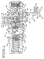
- the modulating relief valve 50 includes a housing 56 having a single bore 58 defined therein, an inlet port 60, a control port 62, an outlet port 64 which is in continuous communication with the control port 62, and a plurality of drain ports 66,68,70,72,74,76. With the exception of the outlet port 64 which is in transverse alignment with control port 62, each of the above-noted ports intersect the single bore 58 at axially spaced locations.
- a valving or valve element such as a spool 80, is slidably disposed in the single bore 58 of the housing 56.
- the valving element 80 has a blind bore 82 defined in one end thereof, and first and second passages 84,86 which interconnect the blind bore 82 and the single bore 58.
- the first and second passages are axially spaced from each other.
- An annular groove 88 is defined on an outer periphery of the spool 80 and the first passage 84 opens into the annular groove 88.
- Another blind bore 90 is defined in the other end of the valve spool 80.
- a second annular groove 92 is defined on the outer periphery of the spool 80 and another passage 94 is defined in the spool 80 and interconnects the blind bore 90 and the annular groove 92.
- the first annular groove 88 is in continuous communication with the drain port 72 while the second annular groove 92 is in continuous communication with the inlet port 60 and in selective communication with the drain port 68.
- a slug 96 is slidably disposed in the second blind bore 90 and defines a pressure chamber 98 between the bottom of the blind bore 90 and one end of the slug 96.
- a load piston 100 is slidably disposed in the single bore 58 adjacent the spool 80 and a pressure chamber 102 is defined in the single bore between the load piston 100 and the spool 80.
- a spring 104 is located in the single bore 58 and contacts the load piston on the side opposite the pressure chamber 102 and biases the load piston 100 towards a first position.
- the load piston moves towards a second position in response to an increase of pressure in the pressure chamber 102 and in opposition to the bias of the spring 104.
- a relief valve 108 is disposed in the load piston 100 and is operative to limit the maximum pressure in the pressure chamber 102.
- the relief valve 108 includes a seat member 110, a ball 112 which is normally in contact with the seat member 110 and a spring 114 which bias the ball to a closed position.
- a means 120 is provided for establishing a ratio between the pressure of the fluid being directed to the force transmitting mechanisms 12,14,16,18 and the pressure of the fluid acting on the load piston 100 of the modulating relief valve 50.
- the establishing means 120 is slidably disposed in the blind bore 82 and retained therein by a lock assembly 122.
- the establishing means 120 includes a ratio valve mechanism 124 movable between first and second positions.
- the ratio valve mechanism 124 includes a valve member 126 which is slidably disposed in the blind bore 82 of the spool 80 and has a first end portion 128, a second end portion 130, and an intermediate portion 132.
- a bore 134 is defined in the valve member 126 and an annular groove 136 is defined in the outer periphery thereof and is in open communication with the bore 134 through a passage 138.
- a restrictive passage, such as an orifice 140 is defined in the second end portion 130 of the valve member 126 adjacent the pressure chamber 102.
- a slug 142 is slidably disposed in the bore 134 of the first end portion 128 and a pressure chamber 144 is defined in the bore 134 between the orifice 140 and the slug 142.
- the second end portion 130 adjacent the pressure chamber 102 has a predetermined cross-sectional area while the cross-sectional area of the slug 142 in the pressure chamber 144 is smaller.
- Figure 3 illustrates a typical pressure curve depicting the various pressure levels in the speed and directional clutches versus time during a change in direction and/or speed when the clutches are being filled and subsequently increasing the pressure therein.
- the solid line 146 represents the pressure in the speed clutches from a point at which the fluid in the clutch is being dumped, filled, and followed by a subsequent controlled rate of rise in the pressure level to the maximum pressure level.
- the dashed line 148 likewise represents the pressure of the fluid in the directional clutches from the time that they are being dumped, filled, and subsequently controllably increased in pressure.
- the ratio establishing means 94 could be in a separate housing.
- the distribution conduit 34 does not need to pass through the housing 56 of the modulating relief valve 50.
- the portion of the distribution conduit 34 downstream of the orifice 54 could be directly connected to the selector valve 28 and another conduit could connect the control port 62 to the distribution conduit 34 thus eliminating the outlet port 64.
- the modulating relief valve with its integral ratio establishing means make up a modulating relief valve assembly.
- pressurized fluid from the pump 20 is directed the speed selector valve 26 through the distribution conduits 30,32 while simultaneously being directed to the directional selector valve 28 through the distribution conduit 34 across the orifices 52,54.
- the distribution conduit 34 also directs the pressurized fluid to the inlet port 60 of the modulating relief valve 50.
- the modulating relief valve 50 maintains the system pressure at the inlet port 60 at its maximum pressure level. Any excess fluid flow is controllably bypassed to the drain port 68 by the movement of the spool 80.
- the spool 80 is movable between a first position at which the spool 80 blocks fluid communication between the inlet port 60 and the drain port 68 and a second position at which the inlet port 60 is in fluid communication with the drain port 68 across the annular groove 92.
- the pressurized fluid from the pump 20 is in continuous communication with the pressure chamber 98 through the annular groove 92 and the passage 94.
- the pressurized fluid in the chamber 98 acting against the slug 96 and the bottom of the blind bore 90 is operative to bias the spool 80 towards its second position thus controllably communicating fluid at the inlet port 60 with the drain port 68.
- the pressurized fluid from the pump 20 is directed through the distribution conduit 34 across the orifice 54 to the control port 62 and subsequently to the pressure chamber 102 through the passage 86, the annular groove 136, the passage 138, the pressure chamber 144, and the orifice 140.
- the fluid pressure in the pressure chamber 102 acting on the end of the spool 80 biases the spool 80 in opposition to the force of the pressurized fluid in the pressure chamber 98.
- the pressurized fluid in the chamber 102 acts against the end of the load piston 100 to move the load piston from its first position towards its second position as shown in Fig. 1 against the bias of the spring 104. Once the load piston 100 reaches the position as shown in Fig.
- the pressurized fluid from the pressure chamber 102 is controllably bypassed to the reservoir 22 through the drain port 74 to maintain a predetermined maximum pressure level in the pressure chamber 102.
- the pressure level in the pressure chamber 98 is approximately four times greater than the pressure in the pressure chamber 102.
- the valve member 126 of the ratio valve mechanism 124 is movable between a first position, as shown in Fig. 1, at which the pressure chamber 102 is blocked from the drain port 72 and a second position at which the pressure chamber 102 is in open communication with the drain port 72 through the passage 84 and the annular groove 88.
- the valve member 126 of the ratio valve mechanism 124 is biased to the first position in response to the pressurized fluid in pressure chamber 144 acting against the slug 142 and is biased towards the second position in response to the fluid pressure in pressure chamber 102.
- the valve member 126 moves to the second position when the pressure of the fluid in pressure chamber 102 exceeds a preselected value with respect to the pressure in the pressure chamber 144.
- the pressure level of the fluid in the pressure chamber 144 is approximately three times higher than the pressure level in the pressure chamber 102 to maintain the valving element 126 in its first position.
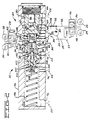
- Fig. 2 illustrates the operation of the fluid system 10 upon placing the directional selector valve 28 and the speed selector valve 26 in one of the operational modes. Due to the filling of the directional clutch 16 and the speed clutch 12, in the operational mode shown, the pressure level of the fluid in the distribution conduits 30,32,34 drops to a very low level, as clearly shown by the representation in Fig. 3 of the lines illustrated at the lower portion of the drawing.
- the pressurized fluid in pressure chamber 102 is quickly dropped to a very low level thus allowing the load piston 100 to fully reset to the position as illustrated in Fig. 2. This happens even though the pressure level in the pressure chamber 144 is still be at a higher pressure level.
- the valving element 80 moves to the left, as viewed in Fig. 2, allowing communication between the inlet port 60 and the drain port 68 to quickly reduce the system pressure.
- the valving element 80 moves to the left since the force established in the pressure chamber 98 is now greater than the resisting force in pressure chamber 102. Consequently, the load piston 100 is totally reset at of prior to the time at which the respective clutches 12,16 are filled and engagement is initiated.
- the pressure level in the respective direction and speed clutches is increased as illustrated by the solid and dashed lines in Fig. 3.
- the fluid pressure in the speed clutch 12 increases from the low fill pressure to the low pressure setting of the relief valve quickly while the pressure level in the directional clutch 16 remains at the lower fill pressure. This is primarily attributed to the differential pressure created by the resistance to fluid flow across the orifice 52. The difference in pressure between the speed clutch and the directional clutch is directly proportional to the size of the orifice 52.
- the flat portion of the solid line 146 which follows the quick increase in pressure is representative of the time needed to complete the filling of the directional clutch 16.
- the corresponding flat portion of the dashed line 148 which parallels the above-noted solid line represents the final filling of the directional clutch before any additional increase in pressure occurs.
- the sudden transition of the solid and dashed lines from flat to vertical indicates that the directional clutch is filled.
- the pressure level then quickly increases to a point at which the spool 80 is in its fluid bypassing condition and the pressure level in chamber 102 is at the level to initiate movement of the load piston 100 against the bias of the spring 104. At this point the rate of pressure rise is controlled by the movement of the load piston 100 against the bias of the spring 104 as illustrated by the slope of the lines in Fig. 3. While the difference in pressure between the two lines of Fig.
- the fluid system as set forth above which incorporates the ratio establishing means provides an arrangement that ensures the load piston being fully reset during tilling of the clutches even though the pressure level in the fluid system reduces at a slower rate.
- This arrangement eliminates the possibility of the clutches being initially engaged at a higher pressure level which creates narsh snocks to the system components. Furthermore, this relationship provides a compact arrangement that is simple in construction and utilizes easy manufacturing techniques.
Landscapes
- Engineering & Computer Science (AREA)
- General Engineering & Computer Science (AREA)
- Mechanical Engineering (AREA)
- Physics & Mathematics (AREA)
- Fluid Mechanics (AREA)
- Chemical & Material Sciences (AREA)
- Combustion & Propulsion (AREA)
- Manufacturing & Machinery (AREA)
- Hydraulic Clutches, Magnetic Clutches, Fluid Clutches, And Fluid Joints (AREA)
- Gear-Shifting Mechanisms (AREA)
Claims (9)
ein modellierendes Druckbegrenzungsventil (50) mit einem Ventilelement (80) und einem Lastkolben (100) beweglich zwischen einer im wesentlichen unbelasteten Position und einer belasteten Position und betriebsmäßig verbunden mit der Quelle (20) und dem Kraftübertragungsmechanismus (16, 18), wobei das modulierende Begrenzungsventil geeignet ist, um die Rate bzw. Geschwindigkeit des Druckanstiegs des Strömungsmittels geleitet zu dem Kraftübertragungsmechanismus zu steuern;
ein Ventilmechanismus einschließlich eines Ventilglieds (126), gleitend in dem einen Ende des Ventilelements (80), benachbart zum Lastkolben (100) und zusammenarbeitet mit letzterem und dem Ventilelement (80), um, das unter Druck stehende Strömungsmittel zum Reservoir abzulassen, wobei das Druckströmungsmittel, auf den Lastkolben während des Füllens des Kraftübertragungsmechanismus wirkt, um den Lastkolben in die im wesentlichen nicht belastete Postition zurückzusetzen; dadurch gekennzeichnet, daß der Ventilmechnismus
ein Verhältnisventil (124) ist mit einer vorbestimmten effektiven Querschnittsfläche ansprechend auf den Druck des auf den Lastkolben wirkenden Strömungsmittels und mit einer kleineren effektiven Querschnittsfläche ansprechend auf den Druck des Strömungsmittels, welches zum Kraftübertragungsmechanismus hingerichtet ist, wobei das Verhältnisventil in der Lage ist, das unter Druck stehende Strömungsmittel zum Reservoir hin abzulassen, und zwar des auf den Lastkolben wirkenden, unter Druck stehenden Strömungsmittels während des Füllens des Kraftübertragungsmechanismus um den Lastkolben in die im wesentlichen nicht belastete Position zurückzusetzen, obwohl der für den Kraftübertragungsmechanismus verfügbare Strömungsmitteldruck auf einem höheren Druck liegt.
ein Gehäuse (56), welches eine Einzelbohrung (58) definiert, einen Einlaßanschluß (60), einen Steueranschluß (62) und eine Vielzahl von Abflußanschlüssen (68, 72, 74), deren jeder die einzelne Bohrung (58) in axial mit Abstand angeordneter Beziehung schneidet;
wobei das Ventilelement (80) zwischen einer ersten Position und einer zweiten Position bewegbar ist, wobei in der ersten Position der Einlaßanschluß (60) gegenüber einem Anschluß (68) der Vielzahl von Abflußanschlüssen blockiert ist, und wobei in der zweiten Position der Einlaßanschluß (60) zu diesem einen Abflußanschluß (68) offen ist, wobei ferner das Ventilelement (80) eine Sackbohrung (82) in einem Ende und eine Ringnut (88) im Außenumfang desselben definiert, wobei ferner ein erster Durchlaß (84) in dem Ventilelement (80) definiert ist, und zwar die Sackbohrung (82) im Ventilelement mit der Ringnut (88) desselben und einem weiteren (72) der Vielzahl von Abflußanschlüssen verbindend, und wobei schließlich ein zweiter Durchlaß (86) in dem Ventilelement (80) definiert ist, und zwar die Sackbohrung (82) in dem Ventilelement und dem Steueranschluß (62) in dem Gehäuse (56) verbindend;
eine in der einzigen Bohrung (58) zwischen dem Lastkolben (100) und dem Ventilelement (80) definierte Druckkammer (102); und
wobei das Verhältnisventil (124) gleitbar zwischen einer ersten Position und einer zweiten Position angeordnet ist, wobei in der ersten Position der erste Durchlaß (84) im Ventilelement gegenüber der Druckkammer (102) blockiert ist, während in der zweiten Position der erste Durchlaß (84) zur Druckkammer (102) hin offen ist, wobei ferner das Verhältnisventil (124) eine vorbestimmte effektive Querschnittsfläche definiert, und zwar in Verbindung mit der Druckkammer (102) sowie eine kleinere effektive Querschnittsfläche in kontinuierlicher offener Verbindung mit dem Steueranschluß (62) durch den zweiten Durchlaß (86) im Ventilelement.
Applications Claiming Priority (2)
| Application Number | Priority Date | Filing Date | Title |
|---|---|---|---|
| US914974 | 1986-10-03 | ||
| US06/914,974 US4751866A (en) | 1986-10-03 | 1986-10-03 | Ratio valve to control unloading of modulating relief valve |
Publications (2)
| Publication Number | Publication Date |
|---|---|
| EP0287573A1 EP0287573A1 (de) | 1988-10-26 |
| EP0287573B1 true EP0287573B1 (de) | 1992-03-18 |
Family
ID=25435029
Family Applications (1)
| Application Number | Title | Priority Date | Filing Date |
|---|---|---|---|
| EP87904483A Expired - Lifetime EP0287573B1 (de) | 1986-10-03 | 1986-12-16 | Verteilerventil zum steuern der öffnung eines dämpfenden ablassventils |
Country Status (11)
| Country | Link |
|---|---|
| US (1) | US4751866A (de) |
| EP (1) | EP0287573B1 (de) |
| JP (1) | JP2776505B2 (de) |
| CN (1) | CN1009748B (de) |
| BR (1) | BR8607212A (de) |
| CA (2) | CA1269913A1 (de) |
| DE (1) | DE3684481D1 (de) |
| HK (1) | HK24394A (de) |
| SG (1) | SG13694G (de) |
| WO (1) | WO1988002449A1 (de) |
| ZA (1) | ZA876964B (de) |
Families Citing this family (16)
| Publication number | Priority date | Publication date | Assignee | Title |
|---|---|---|---|---|
| JPH085394Y2 (ja) * | 1988-05-11 | 1996-02-14 | 株式会社小松製作所 | クラッチ油圧制御装置 |
| US4920861A (en) * | 1989-03-21 | 1990-05-01 | Caterpillar Inc. | Load piston reset control mechanism |
| DE19813982C2 (de) * | 1998-03-28 | 2002-06-20 | Bosch Gmbh Robert | Kupplungssteuerung |
| DE19915557A1 (de) * | 1999-04-07 | 2000-10-12 | Zahnradfabrik Friedrichshafen | Kupplungssystem in einem Getriebe |
| US6227238B1 (en) | 1999-06-21 | 2001-05-08 | Caterpillar Inc. | Valve providing pressure differential proportional to downstream pressure |
| DE10253492A1 (de) * | 2002-11-16 | 2004-05-27 | Zf Friedrichshafen Ag | Einrichtung zur Herstellung der Betriebsbereitschaft einer hydraulischen Betätigungsvorrichtung |
| US8826680B2 (en) * | 2005-12-28 | 2014-09-09 | Johnson Controls Technology Company | Pressure ratio unload logic for a compressor |
| DE102006003517A1 (de) * | 2006-01-24 | 2007-07-26 | Borgwarner Inc., Auburn Hills | Hydraulische Steuereinrichtung und Verfahren zur Ansteuerung zweier Aktuatoren |
| CN103925252B (zh) * | 2014-03-10 | 2017-01-18 | 杭州前进齿轮箱集团股份有限公司 | 一种电控微动阀 |
| SE542286C2 (en) * | 2016-01-25 | 2020-04-07 | Kongsberg Automotive As | Clutch Actuator for reducing Vibrations in a Clutch by a force-reducing gap |
| DE102017203988A1 (de) * | 2017-03-10 | 2018-09-13 | Robert Bosch Gmbh | Überströmventil zur Druckregelung in einem Niederdruckkreislauf eines Kraftstoffeinspritzsystems, Kraftstoffeinspritzsystem |
| FR3080660B1 (fr) * | 2018-04-30 | 2020-03-27 | Poclain Hydraulics Industrie | <P>ENGAGEMENT ET DESENGAGEMENT PROGRESSIF D'UN DISPOSITIF D'EMBRAYAGE POUR VEHICULE</P> |
| JP7014071B2 (ja) * | 2018-07-12 | 2022-02-01 | トヨタ自動車株式会社 | クラッチの断接装置 |
| CN109058319B (zh) * | 2018-09-14 | 2023-12-22 | 中国船舶重工集团公司第七0三研究所 | 阶梯油压调节装置 |
| DE102019110710B3 (de) * | 2019-04-25 | 2020-08-13 | Schaeffler Technologies AG & Co. KG | Ansteuerverfahren für ein Hydrauliksystem mit einer Pumpe und mehreren Ventilen; sowie Hydrauliksystem |
| DE102019110711B4 (de) | 2019-04-25 | 2025-01-30 | Schaeffler Technologies AG & Co. KG | Ansteuerverfahren für ein Hydrauliksystem mit einer Pumpe und Ventilen zum Versorgen mehrerer Verbraucher sowie einer Kühl- und/oder Schmiereinrichtung; und Hydrauliksystem |
Family Cites Families (8)
| Publication number | Priority date | Publication date | Assignee | Title |
|---|---|---|---|---|
| US3566716A (en) * | 1969-07-22 | 1971-03-02 | Int Harvester Co | Clutch cylinder circuit and charging valve therefor |
| US3799308A (en) * | 1972-10-20 | 1974-03-26 | Int Harvester Co | Transmission clutches with feedback controlled pressure modulator |
| US4046160A (en) * | 1976-02-02 | 1977-09-06 | International Harvester Company | Transmission clutches with sequence valve and piston-controlled pressure modulator |
| US4132302A (en) * | 1976-06-07 | 1979-01-02 | International Harvester Company | Transmission clutches with fully-resetting modulator-load-piston |
| IT1084155B (it) * | 1977-08-16 | 1985-05-25 | Trensfluid S R L | Dispositivo idraulico per l'azionamento modulato degli innesti a frizione |
| US4583624A (en) * | 1984-12-10 | 1986-04-22 | Caterpillar Tractor Co. | Fluid system with selective differential pressure control |
| US4676348A (en) * | 1986-03-06 | 1987-06-30 | Caterpillar Inc. | Fluid pressure control system having a timed pressure cutback device |
| US4676349A (en) * | 1986-03-06 | 1987-06-30 | Caterpillar Inc. | Fluid pressure control system having a pressure cutback device |
-
1986
- 1986-10-03 US US06/914,974 patent/US4751866A/en not_active Expired - Lifetime
- 1986-12-16 JP JP62502117A patent/JP2776505B2/ja not_active Expired - Lifetime
- 1986-12-16 WO PCT/US1986/002701 patent/WO1988002449A1/en not_active Ceased
- 1986-12-16 DE DE8787904483T patent/DE3684481D1/de not_active Expired - Fee Related
- 1986-12-16 EP EP87904483A patent/EP0287573B1/de not_active Expired - Lifetime
- 1986-12-16 BR BR8607212A patent/BR8607212A/pt not_active IP Right Cessation
-
1987
- 1987-09-16 ZA ZA876964A patent/ZA876964B/xx unknown
- 1987-09-30 CA CA000548265A patent/CA1269913A1/en active Granted
- 1987-09-30 CN CN87106712A patent/CN1009748B/zh not_active Expired
-
1989
- 1989-09-25 CA CA000612870A patent/CA1272663A/en not_active Expired - Fee Related
-
1994
- 1994-01-26 SG SG13694A patent/SG13694G/en unknown
- 1994-03-17 HK HK243/94A patent/HK24394A/xx unknown
Also Published As
| Publication number | Publication date |
|---|---|
| CN1009748B (zh) | 1990-09-26 |
| EP0287573A1 (de) | 1988-10-26 |
| WO1988002449A1 (en) | 1988-04-07 |
| CA1272663A (en) | 1990-08-14 |
| BR8607212A (pt) | 1988-11-01 |
| SG13694G (en) | 1994-06-10 |
| CN87106712A (zh) | 1988-09-14 |
| DE3684481D1 (de) | 1992-04-23 |
| HK24394A (en) | 1994-03-25 |
| US4751866A (en) | 1988-06-21 |
| JP2776505B2 (ja) | 1998-07-16 |
| ZA876964B (en) | 1988-03-21 |
| JPH01501651A (ja) | 1989-06-08 |
| CA1272663C (de) | 1990-08-14 |
| CA1269913A1 (en) | 1990-06-05 |
Similar Documents
| Publication | Publication Date | Title |
|---|---|---|
| EP0287573B1 (de) | Verteilerventil zum steuern der öffnung eines dämpfenden ablassventils | |
| EP0066151B1 (de) | Hydrauliches Steuersystem mit vorgesteuertem Rückschlagventil | |
| EP0331076B1 (de) | Hydraulische Schaltung für Zylinder | |
| US4480527A (en) | Power transmission | |
| US3878864A (en) | Bypass valve | |
| US4089166A (en) | Automatic pump control system | |
| US4204459A (en) | Combination check and flow control valve for hydraulic systems | |
| US4353289A (en) | Power transmission | |
| JPS6242839B2 (de) | ||
| US4620560A (en) | Modulating relief valve with dual functioning load piston | |
| US4102250A (en) | Load check and bypass valve | |
| US4583624A (en) | Fluid system with selective differential pressure control | |
| US5778929A (en) | Directional control valve assembly having a pressure compensation valve | |
| US4865176A (en) | Modulating inching valve with automatic pressure control | |
| US4286502A (en) | Hydraulic load lifting system with automatic blocking valve | |
| EP0414826B1 (de) | Steuervorrichtung zur rückstellung eines lastkolbens | |
| US4062374A (en) | Hydraulic valves and hydraulic systems | |
| US4650048A (en) | Control system for transmission engagement | |
| US4320691A (en) | Hydraulic load lifting system with hydraulic surcharge to make up valve pilot lines | |
| EP0053608B1 (de) | Ventilsystem | |
| US3612088A (en) | Throttling draft control valve | |
| CA2010702A1 (en) | Laod piston reset control mechanism | |
| WO1993013319A1 (en) | Fluid control for two independent actuators | |
| GB1585139A (en) | Load responsive fluid control valve | |
| JP3708725B2 (ja) | 油圧制御装置 |
Legal Events
| Date | Code | Title | Description |
|---|---|---|---|
| PUAI | Public reference made under article 153(3) epc to a published international application that has entered the european phase |
Free format text: ORIGINAL CODE: 0009012 |
|
| 17P | Request for examination filed |
Effective date: 19880614 |
|
| AK | Designated contracting states |
Kind code of ref document: A1 Designated state(s): DE FR GB IT |
|
| 17Q | First examination report despatched |
Effective date: 19891010 |
|
| GRAA | (expected) grant |
Free format text: ORIGINAL CODE: 0009210 |
|
| AK | Designated contracting states |
Kind code of ref document: B1 Designated state(s): DE FR GB IT |
|
| REF | Corresponds to: |
Ref document number: 3684481 Country of ref document: DE Date of ref document: 19920423 |
|
| ITF | It: translation for a ep patent filed | ||
| ET | Fr: translation filed | ||
| PGFP | Annual fee paid to national office [announced via postgrant information from national office to epo] |
Ref country code: FR Payment date: 19921103 Year of fee payment: 7 |
|
| PLBE | No opposition filed within time limit |
Free format text: ORIGINAL CODE: 0009261 |
|
| STAA | Information on the status of an ep patent application or granted ep patent |
Free format text: STATUS: NO OPPOSITION FILED WITHIN TIME LIMIT |
|
| 26N | No opposition filed | ||
| PG25 | Lapsed in a contracting state [announced via postgrant information from national office to epo] |
Ref country code: FR Effective date: 19940831 |
|
| REG | Reference to a national code |
Ref country code: FR Ref legal event code: ST |
|
| PGFP | Annual fee paid to national office [announced via postgrant information from national office to epo] |
Ref country code: GB Payment date: 19941107 Year of fee payment: 9 |
|
| PG25 | Lapsed in a contracting state [announced via postgrant information from national office to epo] |
Ref country code: GB Effective date: 19951216 |
|
| GBPC | Gb: european patent ceased through non-payment of renewal fee |
Effective date: 19951216 |
|
| PGFP | Annual fee paid to national office [announced via postgrant information from national office to epo] |
Ref country code: DE Payment date: 20010917 Year of fee payment: 16 |
|
| PG25 | Lapsed in a contracting state [announced via postgrant information from national office to epo] |
Ref country code: DE Free format text: LAPSE BECAUSE OF NON-PAYMENT OF DUE FEES Effective date: 20030701 |
|
| PG25 | Lapsed in a contracting state [announced via postgrant information from national office to epo] |
Ref country code: IT Free format text: LAPSE BECAUSE OF NON-PAYMENT OF DUE FEES Effective date: 20051216 |