EP0287494A2 - Drahtbearbeitungsmaschine - Google Patents
Drahtbearbeitungsmaschine Download PDFInfo
- Publication number
- EP0287494A2 EP0287494A2 EP88600005A EP88600005A EP0287494A2 EP 0287494 A2 EP0287494 A2 EP 0287494A2 EP 88600005 A EP88600005 A EP 88600005A EP 88600005 A EP88600005 A EP 88600005A EP 0287494 A2 EP0287494 A2 EP 0287494A2
- Authority
- EP
- European Patent Office
- Prior art keywords
- wire
- rollers
- bending
- pins
- cutter
- Prior art date
- Legal status (The legal status is an assumption and is not a legal conclusion. Google has not performed a legal analysis and makes no representation as to the accuracy of the status listed.)
- Withdrawn
Links
- 238000012545 processing Methods 0.000 title claims abstract 4
- 238000005452 bending Methods 0.000 claims abstract description 28
- 238000005520 cutting process Methods 0.000 claims abstract description 10
- 230000007246 mechanism Effects 0.000 claims abstract description 5
- 230000005540 biological transmission Effects 0.000 claims description 17
- 239000002184 metal Substances 0.000 claims description 12
- 239000003550 marker Substances 0.000 claims description 4
- 230000003068 static effect Effects 0.000 claims description 3
- 241000743339 Agrostis Species 0.000 claims description 2
- 230000002844 continuous effect Effects 0.000 claims 2
- 150000001875 compounds Chemical class 0.000 claims 1
- 230000033001 locomotion Effects 0.000 description 10
- 238000013459 approach Methods 0.000 description 3
- 238000007789 sealing Methods 0.000 description 3
- 241001442234 Cosa Species 0.000 description 1
- 239000005018 casein Substances 0.000 description 1
- BECPQYXYKAMYBN-UHFFFAOYSA-N casein, tech. Chemical compound NCCCCC(C(O)=O)N=C(O)C(CC(O)=O)N=C(O)C(CCC(O)=N)N=C(O)C(CC(C)C)N=C(O)C(CCC(O)=O)N=C(O)C(CC(O)=O)N=C(O)C(CCC(O)=O)N=C(O)C(C(C)O)N=C(O)C(CCC(O)=N)N=C(O)C(CCC(O)=N)N=C(O)C(CCC(O)=N)N=C(O)C(CCC(O)=O)N=C(O)C(CCC(O)=O)N=C(O)C(COP(O)(O)=O)N=C(O)C(CCC(O)=N)N=C(O)C(N)CC1=CC=CC=C1 BECPQYXYKAMYBN-UHFFFAOYSA-N 0.000 description 1
- 235000021240 caseins Nutrition 0.000 description 1
- 230000003247 decreasing effect Effects 0.000 description 1
- 238000000034 method Methods 0.000 description 1
- 238000012544 monitoring process Methods 0.000 description 1
- 238000010008 shearing Methods 0.000 description 1
- 239000000126 substance Substances 0.000 description 1
- 238000012800 visualization Methods 0.000 description 1
- 230000001755 vocal effect Effects 0.000 description 1
Images

Classifications
-
- B—PERFORMING OPERATIONS; TRANSPORTING
- B21—MECHANICAL METAL-WORKING WITHOUT ESSENTIALLY REMOVING MATERIAL; PUNCHING METAL
- B21F—WORKING OR PROCESSING OF METAL WIRE
- B21F1/00—Bending wire other than coiling; Straightening wire
- B21F1/02—Straightening
Definitions
- the invention refers to a machine which process circular section wire, including straightening, two directional bending and cutting.
- the machine consists of: -a system forcing torsion , pulling and steaightening.
- -a bending system capable of bending the wire in two directions with adjustable curvutuve radius and mounted cutter, which follows wire while bending and may cut the wire in any position.
- the upper straightening rollers are not driven directly and they force a slight wire torsion, as it is explained analytically in the following.
- the advantage of the bending system is that only two pins are used for two direction bending. In each bending one acts as the pin around which wire is bent and the other one as the bending pin. For counter bents functions of both pins alternate.
- the on the benter fixed cutter enables cutting of wire while bender is rotated or directly after bent, without leaving a straight portion if desirable.
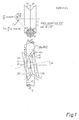
- the above mentioned function is explained analytically using figs 1,2,3.
- roller plane is rotated by an angle(w), around an axis vertical to OX and passing through the roller centerpoint, torsion of the straightened and pulled rod is achieved as it is proved theoretically and practically.
- the rotation of the roller plane thus deviating from the up to now used through OXpassing plane and the important result achieved through this rotation on the controlled rod torsion build the substance of the here described invention.
- This controlled torsion enables forming of perfect 2 - D shapes and complicated 3-D shapes on automatic rod bending machines.
- roller (1) is rotated by an angle (w), counterclockwise in Fig (1), taking position (1′) and contacting rods on points (E1) and (E2).
- Points (E1) and (E2) move both on the with a relocity ( u ) pulled rod (2) and on the with the vocational speed ( V ) rotating roller.
- the number of the non adjustable rollers (1) as well as of the adjustable ones(2) may be anyone.
- the numbers of non adjustable and adjustable rollers may be equal to each other or differ by one.
- the distances between the non adjustable rollers and the distances between the adjustable ones may be equal to each other or differ from each other.
- Non adjustable and adjustable rollers may have or may not have grooves.
- metal wire(14) is put between rollers(1)and (2). Trapping of metal wire (14) between non adjustable(1)and adjustable rollers(2) is acheived by moving the laters to the formers. Moveme- is acheived by pistons(12), which stretch out pressing through housing (11) shaft(10), bearing the disks with adjustable pins(9).
- the number of disks(9) is equal to the number of the adjustable rollers(2).Each disk(9) bears some adjustable pins(15), placed if possible on the corners of a regular polygon. The length of each pin (15) may be adjusted through a bolt.
- the pins (15) are grouped. Each group has a pin number, equal to the disks(9) and the pins of every group, belonging one to each disk, lay on the same, through shaft (10) passing level.
- the disks (9) are actually normal to the shaft (10), but for visualization purposes are drawn , turned by 90° on the drawing level.
- the disk shaft positioner (13) defines the pin group, which will press the adjustable roller supports(4) through rotation of shaft(10).
- non adjustable rollers (1) are driven by motor (3) in rotation direction (17) , wire moves towards pulling direction(16).
- Any type of motor may be used , but the hydraulic one gives best performance.
- Roller driving may be also supplied by more than one motors , each motor driv ing one group of rollers(1). In Fig.2 , only one motor (3) is presented schematically through a chain of all the non adjustable rollers(1). If the rotation direction (17) of motor (3) is reversed wire pulling direction(16) changes.
- a group of pins (15) is preset, having preset the lengths of the pins to give best pulling and straightening, as it is described later on.
- setting of the feeder is acheived very quickly and preciselyfor the wire diameter to be feeded.
- the end of the approach between rollers is determined by the pistons.(12).
- adjustable rollers (2) in respect to the non adjustable rollers(1) guarantees a plastic deformation of the wire on the contact points between wire and rollers. This deformation differs from roller to roller depending on the setting of the respective pin(15)
- the elastic comeback of the wire after its plastic deformation is exactly sufficient to give ti the wir a straight form on the level, which is normal to the paper level of the drawing.
- a second mechanism is required, similar to the one described above. Its rollers should lay in a level normal to the drawing level, and it should be located directly after the first one in a distance not causin plastic deformation to the processed wire.
- the adjustable rollers supports(4) may be rotated round the axis of rotation(18), using levers(6) and the common transmission bar(7), driven by the double direction piston (8) to left or to right.
- the roller support(4) rotates in its housing (5) around axis (18) by a small angle to the right or to the left in respect to the drawing level.Due to friction , rotation of rollers(2) around axis (18) results to torsional movement of the pulled rod. This achievement is documented in my patent Nr87.0596/t.8 76/s.-191 of April 14th 1987, 00.30am.
- Housing (10) remain always , parallel to itself, on level O ⁇ X.
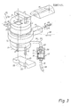
- the rotating body (1) of the bender may rotate freely , driven by a motor, fixed on body(1), through the chain gear(23) and the chain(24).
- chain motion may have two directions: (31) and (32).
- the rotating body(1) ends up at the interchangeable upper part(2) and down at the interchangeable lower part(3).
- Parts (2) and (3) are fastened to body(1) by means of belts
- the interchangeable upper parts(2) bears: a square opening through which passes the moving cutter (9), the upper left(6) and upper right (7) pins of the cutter (8).
- Pins (6) and (7) locate the fixed cutter (8) at a certain distance from the upper level of (2) and on the other hand, they provide bending of the rod(21) passing between them.
- the interchangeable lower part (3) bears only the lower left pin (5) and the lower right pin.
- the draw-back spring (22) keeps housing (10) in such a position that at least of pins (4) or (5) is placed inside the grooves (25) or (26) of plate (13) respectively.
- the distance between the centerpoints of the semicircular grooves(25) and (26), the distance between the centerpoints of the upper pins (6) and (7) are equal to each other Pins (4) and (5), as well as pins (6) and (7) may bear outer rings, to prevent their wear.
- the outer diameter of pins(4) and (5) is equal to the diameter of grooves (25) and (26) respectively.
- the outer diameter of pins (6) and (7) is equal to the inner diameter of the circles we want to form on the processed rod.
- Metal rod (21) goes through pins (6) and (7) after passing through the fixed wire guide(11).
- Moving cutter is driven by a hydraulic piston, located in the rotating body. (1). These are one direction pistons . They are pushed by high pressure oil and they are drawn back by a strong spring. Position of moving cutter(9) is of great importance for a) decreasing the moving cutter stroke in small diameter rods and b) for givving next command to the bending head, directly after cutting.
- the position marker (17) supplies outside information about the position of transmission piston (14).Both resulting spaces of the flexible pipe, (27) and (28), are filled with oil after removing air.
Landscapes
- Engineering & Computer Science (AREA)
- Mechanical Engineering (AREA)
- Wire Processing (AREA)
Applications Claiming Priority (6)
| Application Number | Priority Date | Filing Date | Title |
|---|---|---|---|
| GR870596 | 1987-04-14 | ||
| GR870596A GR870596B (en) | 1987-04-14 | 1987-04-14 | Method for rotating a metallic rod around the axis of it during the lining by rowls |
| GR870865A GR870865B (en) | 1987-06-03 | 1987-06-03 | Arrangement for providing machines with circular cross section wire able to push revolve line the wires and regulation for all diameters |
| GR870865 | 1987-06-03 | ||
| GR870866 | 1987-06-03 | ||
| GR870866A GR870866B (en) | 1987-06-03 | 1987-06-03 | Bending machine for small diameter wires |
Publications (2)
| Publication Number | Publication Date |
|---|---|
| EP0287494A2 true EP0287494A2 (de) | 1988-10-19 |
| EP0287494A3 EP0287494A3 (de) | 1990-08-01 |
Family
ID=27269862
Family Applications (1)
| Application Number | Title | Priority Date | Filing Date |
|---|---|---|---|
| EP88600005A Withdrawn EP0287494A3 (de) | 1987-04-14 | 1988-04-06 | Drahtbearbeitungsmaschine |
Country Status (2)
| Country | Link |
|---|---|
| EP (1) | EP0287494A3 (de) |
| ES (1) | ES2023101A4 (de) |
Cited By (5)
| Publication number | Priority date | Publication date | Assignee | Title |
|---|---|---|---|---|
| EP0564444A1 (de) * | 1992-04-03 | 1993-10-06 | EVG Entwicklungs- u. Verwertungs- Gesellschaft m.b.H. | Vorrichtung zum kontinuierlichen Fördern eines Materialstranges zu einer Verarbeitungsanlage |
| EP0800876A3 (de) * | 1996-04-12 | 1998-05-20 | Progress Ag | Richtmaschine |
| CN109175155A (zh) * | 2018-11-19 | 2019-01-11 | 无锡腾佳机械科技有限公司 | 双速钢筋调直切断机 |
| CN118371630A (zh) * | 2024-05-09 | 2024-07-23 | 万臻(山东)稀土科技有限公司 | 一种铝钛硼丝送丝机构 |
| CN119076832A (zh) * | 2024-11-08 | 2024-12-06 | 新乡妃她医疗科技有限公司 | 一种矫治器用钢丝自动弯制设备 |
Family Cites Families (2)
| Publication number | Priority date | Publication date | Assignee | Title |
|---|---|---|---|---|
| US3706215A (en) * | 1971-02-19 | 1972-12-19 | Herbert D Horton | Rotary pipe straightener |
| FR2591132B1 (fr) * | 1985-12-05 | 1989-09-15 | Senelonge Henri | Dresse-fil et installation de redressement de fils a plusieurs dresse-fils. |
-
1988
- 1988-04-06 EP EP88600005A patent/EP0287494A3/de not_active Withdrawn
- 1988-04-06 ES ES88600005T patent/ES2023101A4/es active Pending
Cited By (6)
| Publication number | Priority date | Publication date | Assignee | Title |
|---|---|---|---|---|
| EP0564444A1 (de) * | 1992-04-03 | 1993-10-06 | EVG Entwicklungs- u. Verwertungs- Gesellschaft m.b.H. | Vorrichtung zum kontinuierlichen Fördern eines Materialstranges zu einer Verarbeitungsanlage |
| EP0800876A3 (de) * | 1996-04-12 | 1998-05-20 | Progress Ag | Richtmaschine |
| CN109175155A (zh) * | 2018-11-19 | 2019-01-11 | 无锡腾佳机械科技有限公司 | 双速钢筋调直切断机 |
| CN109175155B (zh) * | 2018-11-19 | 2024-01-19 | 无锡腾佳机械科技有限公司 | 双速钢筋调直切断机 |
| CN118371630A (zh) * | 2024-05-09 | 2024-07-23 | 万臻(山东)稀土科技有限公司 | 一种铝钛硼丝送丝机构 |
| CN119076832A (zh) * | 2024-11-08 | 2024-12-06 | 新乡妃她医疗科技有限公司 | 一种矫治器用钢丝自动弯制设备 |
Also Published As
| Publication number | Publication date |
|---|---|
| EP0287494A3 (de) | 1990-08-01 |
| ES2023101A4 (es) | 1992-01-01 |
Similar Documents
| Publication | Publication Date | Title |
|---|---|---|
| EP0152224B1 (de) | Vorrichtung zum Herstellen von in mehreren Richtungen gebogenen Gegenständen | |
| KR101419698B1 (ko) | 열간 코일스프링 제조장치 | |
| US3680347A (en) | Bending machine | |
| EP0491195B1 (de) | Biege-Formeinrichtung von Stangen und Verfahren zum Einbringen von Biegungen der hinteren Enden von Stangen | |
| US5014533A (en) | Wire processing machine | |
| CA1332805C (en) | Automatic machine for producing frames for spring mattresses from circular or flat wire | |
| US4843859A (en) | Pipe bender | |
| GB2245850A (en) | Automatic spring-making machine | |
| GB1227614A (de) | ||
| US3296851A (en) | Wire-bending machine | |
| GB1604963A (en) | Bending machines | |
| US5904059A (en) | Straightening apparatus | |
| EP0880415B1 (de) | Vorrichtung zum richten von draht | |
| US6782728B2 (en) | Tube bending machine | |
| US296269A (en) | Machine for bending wire | |
| US4112727A (en) | Method and apparatus for making pipe flanges | |
| US2295953A (en) | Material handling apparatus | |
| RU2622197C1 (ru) | Устройство для изготовления изогнутых труб | |
| EP0063041A2 (de) | Verfahren und Vorrichtung zum stufenweisen Biegen | |
| EP0037415B1 (de) | Federwicklungsmaschine mit verbesserter antriebsvorrichtung für die zuführrolle | |
| CN113102649A (zh) | 一种蛇形折弯机 | |
| EP0827791A2 (de) | Vorrichtung zum Richten von Draht | |
| US4090381A (en) | Device for drawing-off and straightening cylindrically shaped stock | |
| US3053307A (en) | Stock straightening apparatus | |
| KR100388641B1 (ko) | 커팅블레이드의 절곡 및 절단장치 |
Legal Events
| Date | Code | Title | Description |
|---|---|---|---|
| PUAI | Public reference made under article 153(3) epc to a published international application that has entered the european phase |
Free format text: ORIGINAL CODE: 0009012 |
|
| AK | Designated contracting states |
Kind code of ref document: A2 Designated state(s): AT CH DE ES FR GB IT LI |
|
| PUAL | Search report despatched |
Free format text: ORIGINAL CODE: 0009013 |
|
| AK | Designated contracting states |
Kind code of ref document: A3 Designated state(s): AT CH DE ES FR GB IT LI |
|
| 17P | Request for examination filed |
Effective date: 19901012 |
|
| REG | Reference to a national code |
Ref country code: ES Ref legal event code: BA2A Ref document number: 2023101 Country of ref document: ES Kind code of ref document: A4 |
|
| 17Q | First examination report despatched |
Effective date: 19920331 |
|
| RAP3 | Party data changed (applicant data changed or rights of an application transferred) |
Owner name: ANAGNOSTOPOULOS, PANAGHIOTIS A. |
|
| STAA | Information on the status of an ep patent application or granted ep patent |
Free format text: STATUS: THE APPLICATION IS DEEMED TO BE WITHDRAWN |
|
| 18D | Application deemed to be withdrawn |
Effective date: 19941026 |