EP0287058B1 - Manikin for practising artificial respiration - Google Patents
Manikin for practising artificial respiration Download PDFInfo
- Publication number
- EP0287058B1 EP0287058B1 EP88105873A EP88105873A EP0287058B1 EP 0287058 B1 EP0287058 B1 EP 0287058B1 EP 88105873 A EP88105873 A EP 88105873A EP 88105873 A EP88105873 A EP 88105873A EP 0287058 B1 EP0287058 B1 EP 0287058B1
- Authority
- EP
- European Patent Office
- Prior art keywords
- manikin
- mouth
- bag
- cover
- simulating
- Prior art date
- Legal status (The legal status is an assumption and is not a legal conclusion. Google has not performed a legal analysis and makes no representation as to the accuracy of the status listed.)
- Expired
Links
- 230000029058 respiratory gaseous exchange Effects 0.000 title claims description 4
- 210000004072 lung Anatomy 0.000 claims description 13
- 238000000034 method Methods 0.000 claims description 3
- 239000000463 material Substances 0.000 description 5
- 210000003625 skull Anatomy 0.000 description 5
- 239000012528 membrane Substances 0.000 description 3
- 239000004033 plastic Substances 0.000 description 3
- 238000007789 sealing Methods 0.000 description 3
- 230000007423 decrease Effects 0.000 description 2
- 239000013013 elastic material Substances 0.000 description 2
- 238000009825 accumulation Methods 0.000 description 1
- 239000011324 bead Substances 0.000 description 1
- 230000008602 contraction Effects 0.000 description 1
- 208000015181 infectious disease Diseases 0.000 description 1
- 230000002458 infectious effect Effects 0.000 description 1
- 239000002985 plastic film Substances 0.000 description 1
- 229920006255 plastic film Polymers 0.000 description 1
- 238000004088 simulation Methods 0.000 description 1
Images


Classifications
-
- G—PHYSICS
- G09—EDUCATION; CRYPTOGRAPHY; DISPLAY; ADVERTISING; SEALS
- G09B—EDUCATIONAL OR DEMONSTRATION APPLIANCES; APPLIANCES FOR TEACHING, OR COMMUNICATING WITH, THE BLIND, DEAF OR MUTE; MODELS; PLANETARIA; GLOBES; MAPS; DIAGRAMS
- G09B23/00—Models for scientific, medical, or mathematical purposes, e.g. full-sized devices for demonstration purposes
- G09B23/28—Models for scientific, medical, or mathematical purposes, e.g. full-sized devices for demonstration purposes for medicine
- G09B23/288—Models for scientific, medical, or mathematical purposes, e.g. full-sized devices for demonstration purposes for medicine for artificial respiration or heart massage
Definitions
- This invention relates to a manikin for practising artificial respiration by the mouth-to-mouth or mouth-to-nose method, said manikin comprising an inflatable element simulating a lung (in the following referred to as the lung), an element simulating a chest (in the following referred to as the chest) and a hollow element simulating a head (in the following referred to as the head), said head having a cavity containing a replaceable inflatable bag having an air inlet which is airtightly connected with a replaceable element simulating a mouth and nose, the cavity in the head being connected with the lung through an air duct.
- a manikin for practising artificial respiration by the mouth-to-mouth or mouth-to-nose method
- said manikin comprising an inflatable element simulating a lung (in the following referred to as the lung), an element simulating a chest (in the following referred to as the chest) and a hollow element simulating a head (in the following referred to as the head), said
- the replaceable inflatable bag of the prior art manikin is preferably made from a non-elastic material and it has such a shape that it collapses when the lung returns to its non-inflated state which occurs when the user removes his mouth from the nose and mouth element of the manikin and allows the pressure within the bag to return to atmospheric pressure. Concurrently with the collapse of the bag, air which during the inflation of the bag was introduced into the cavity of the head and further into the lung through the air duct flows back to the cavity in the head.
- the bag does not collapse completely when the lung has returned to its non-inflated state.
- the object of the invention is to eliminate or reduce the above mentioned drawbacks caused by leakages, if any, in the secondary air system.
- manikin of the invention which manikin is characterized in that the bag is surrounded by an elastically expandable cover made from a woven or knitted body wholly or partially consisting of elastic threads or yarn, said cover having a predetermined internal volume in its state of rest.
- the elastically expandable cover ensures that the bag following each cycle, i.e. inflation followed by deflation by pressure relief, collapses to the same extent i.e. corresponding to the internal volume of the cover in its state of rest. Consequently, there will be no accumulation of air in the bag even after extended use of the manikin.
- the use of a combination of a bag and a surrounding elastically expandable cover also presents the advantage that it is possible to use a simple and inexpensive bag.
- the bag may be prepared from an inexpensive plastic film or paper.
- the cover does not have to be airtight and it should only be capable of ensuring that the bag collapses in a reproducible manner and should not present an unacceptable resistance against expansion.
- the cover is preferably tubular.
- a tubular dressing material which is commercially available under the trade mark "Surgifix" is a particularly suitable cover material.
- the cover is preferably permanently attached to the head because it does not have to be replaced when the bag is replaced.
- a subatmospheric pressure may be created in connection with the collapse of the bag caused by the cover.
- the manikin illustrated in the drawings comprises a head 1 which via a neck portion 2 is connected with a chest 3.
- the head 1 comprises a skull 4 having a cavity 5.
- the front side of the skull 4 comprises a hole, and a sealing ring 6, e.g. a rubber ring, is inserted in the hole.
- the inner side of the sealing ring 6 comprises an annular groove 7, and a ring 8, e.g. consisting of a hard plastic material, is mounted in the groove 7.
- the ring 8 maintains one end of a tubular, elastically expandable cover 9 in the groove 7.
- the opposite end of the tubular cover 9 is located close to the rear side of the skull 4 both in the state of rest (Fig. 1) and in its expanded state (Fig. 2).
- the head 1 also comprises a replaceable mouth and nose element 10 e.g. made from soft plastic material and comprising a hole 11 simulating a mouth and openings 12 simulating nostrils.
- a replaceable mouth and nose element 10 e.g. made from soft plastic material and comprising a hole 11 simulating a mouth and openings 12 simulating nostrils.
- the mouth and nose element 10 comprises an internal groove and a radially extending annular flange 13 of a bushing 14, e.g. made from a hard plastic material, is inserted in the annular groove.
- the bushing 14 is inserted in the opening of an inflatable bag 15, said bag 15 being maintained between the exterior side of the bushing 14 and an internal annular bead 16 on the sealing ring 6.
- the manikin illustrated in the drawings also comprises an air duct 20 connected with the cavity 5 and comprising a spring activated one-way valve 21 which opens when the pressure within the air duct 20 decreases to a subatmospheric pressure.
- the air duct 20 is connected to a cavity 22 in the chest 3, said cavity 22 being covered by an expandable membrane 23.
- the manikin illustrated is used in the following manner: Before staring the use of the manikin the mouth and nose element 10 is removed together with the bushing 14 so as to allow a previously used bag 15, if any, to be removed and replaced with a new one together with a new mouth and nose element 10 and a bushing 14.
- the user blows air into the mouth and nose element 10 through the openings 12 and the hole 11, respectively, and the hole 11 or the openings 12 are covered by a finger.
- the bag 15 By introducing air into the nose and mouth element 10, the bag 15 is caused to be inflated and the cover 9 is expanded.
- the collapse of the bag 15 is caused partly by the superatmospheric pressure in the cavity 5 and partly by the cover 9 which contracts to its state of rest.
- the state of rest of the cover 9 is predetermined and does not depend on leakages, if any, in the secondary air system.
- the bag 15 will have the same content of air at the start of each practising cycle.
Landscapes
- Engineering & Computer Science (AREA)
- Health & Medical Sciences (AREA)
- General Physics & Mathematics (AREA)
- Physics & Mathematics (AREA)
- Mathematical Analysis (AREA)
- Mathematical Optimization (AREA)
- Medical Informatics (AREA)
- Medicinal Chemistry (AREA)
- Chemical & Material Sciences (AREA)
- Algebra (AREA)
- Computational Mathematics (AREA)
- Heart & Thoracic Surgery (AREA)
- Cardiology (AREA)
- General Health & Medical Sciences (AREA)
- Mathematical Physics (AREA)
- Pure & Applied Mathematics (AREA)
- Business, Economics & Management (AREA)
- Educational Administration (AREA)
- Educational Technology (AREA)
- Theoretical Computer Science (AREA)
- Respiratory Apparatuses And Protective Means (AREA)
- Toys (AREA)
- Instructional Devices (AREA)
- Orthopedics, Nursing, And Contraception (AREA)
Description
- This invention relates to a manikin for practising artificial respiration by the mouth-to-mouth or mouth-to-nose method, said manikin comprising an inflatable element simulating a lung (in the following referred to as the lung), an element simulating a chest (in the following referred to as the chest) and a hollow element simulating a head (in the following referred to as the head), said head having a cavity containing a replaceable inflatable bag having an air inlet which is airtightly connected with a replaceable element simulating a mouth and nose, the cavity in the head being connected with the lung through an air duct.
- Document DE-A-2 144 931 describes a manikin of the above mentioned type.
- The replaceable inflatable bag of the prior art manikin is preferably made from a non-elastic material and it has such a shape that it collapses when the lung returns to its non-inflated state which occurs when the user removes his mouth from the nose and mouth element of the manikin and allows the pressure within the bag to return to atmospheric pressure. Concurrently with the collapse of the bag, air which during the inflation of the bag was introduced into the cavity of the head and further into the lung through the air duct flows back to the cavity in the head.
- If the secondary air system, i.e. that part of the cavity of the head which surrounds the bag, the air duct and the lung, leaks - and in practise leakages often occur - air will pass from the secondary air system to the surrounding atmosphere during the inflation of the lung.
- Therefore, the bag does not collapse completely when the lung has returned to its non-inflated state.
- Consequently a reduced amount of air will be introduced into the air duct and the lung during a new inflation of the bag and the amount of air introduced will decrease further during each subsequent cycle.
- Due to the accumulating amounts of air in the bag even minor leakages in the secondary air system will cause such changes during each practising cycle that the manikin gradually ceases to function anatomically correct and in a reproducible manner.
- It has been attempted to use a bag of an elastic material, e.g. a rubber balloon, but in that case the simulation of the resistance against inflation of the lung and the chest rather depends on the properties of the rubber balloon than on the properties of the lung, and consequently the use of the manikin becomes less realistic. Furthermore, such a rubber balloon has to meet high quality requirements which make the balloon expensive and increase the costs of practising. Thus, for hygienic reasons and in particular in order to reduce the risk of spreading of infectious matter a new balloon has to be inserted when a new person starts practising.
- The object of the invention is to eliminate or reduce the above mentioned drawbacks caused by leakages, if any, in the secondary air system.
- This object and other objects which will appear from the following description are achieved by the manikin of the invention which manikin is characterized in that the bag is surrounded by an elastically expandable cover made from a woven or knitted body wholly or partially consisting of elastic threads or yarn, said cover having a predetermined internal volume in its state of rest.
- The elastically expandable cover ensures that the bag following each cycle, i.e. inflation followed by deflation by pressure relief, collapses to the same extent i.e. corresponding to the internal volume of the cover in its state of rest. Consequently, there will be no accumulation of air in the bag even after extended use of the manikin.
- It is unnecessary to replace the elastically expandable cover after each person's use of the manikin because the cover is not contacted by the expiration air of the user. Thus, it is possible to use a relatively expensive cover without any significant increase in the costs of using the manikin.
- The use of a combination of a bag and a surrounding elastically expandable cover also presents the advantage that it is possible to use a simple and inexpensive bag. Thus, the bag may be prepared from an inexpensive plastic film or paper.
- The cover does not have to be airtight and it should only be capable of ensuring that the bag collapses in a reproducible manner and should not present an unacceptable resistance against expansion.
- The cover is preferably tubular.
- A tubular dressing material which is commercially available under the trade mark "Surgifix" is a particularly suitable cover material.
- The cover is preferably permanently attached to the head because it does not have to be replaced when the bag is replaced.
- In case of minor leakages in the secondary air system a subatmospheric pressure may be created in connection with the collapse of the bag caused by the cover. In such cases it is preferably to provide a one-way valve in the secondary air system, the one-way valve allowing air to flow from the surrounding atmosphere into the secondary air system when the pressure within the secondary air system is subatmospheric.
- The invention will now be described in further detail with reference to the drawings in which
- Fig. 1
- shows a sectional view of a preferred embodiment of a manikin according to the invention with a collapsed bag and a collapsed cover.
- Fig. 2
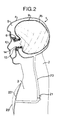
- shows a sectional view of the manikin according to Fig. 1 with an inflated bag and an expanded cover and
- Fig. 3
- shows a sectional view of the nose and mouth element of the manikin according to the invention on an enlarged scale
- The manikin illustrated in the drawings comprises a head 1 which via a
neck portion 2 is connected with a chest 3. The head 1 comprises askull 4 having acavity 5. The front side of theskull 4 comprises a hole, and asealing ring 6, e.g. a rubber ring, is inserted in the hole. The inner side of thesealing ring 6 comprises an annular groove 7, and a ring 8, e.g. consisting of a hard plastic material, is mounted in the groove 7. The ring 8 maintains one end of a tubular, elasticallyexpandable cover 9 in the groove 7. The opposite end of thetubular cover 9 is located close to the rear side of theskull 4 both in the state of rest (Fig. 1) and in its expanded state (Fig. 2). - The head 1 also comprises a replaceable mouth and
nose element 10 e.g. made from soft plastic material and comprising ahole 11 simulating a mouth andopenings 12 simulating nostrils. - The mouth and
nose element 10 comprises an internal groove and a radially extendingannular flange 13 of a bushing 14, e.g. made from a hard plastic material, is inserted in the annular groove. Thebushing 14 is inserted in the opening of aninflatable bag 15, saidbag 15 being maintained between the exterior side of thebushing 14 and an internalannular bead 16 on the sealingring 6. - The manikin illustrated in the drawings also comprises an
air duct 20 connected with thecavity 5 and comprising a spring activated one-way valve 21 which opens when the pressure within theair duct 20 decreases to a subatmospheric pressure. Theair duct 20 is connected to acavity 22 in the chest 3, saidcavity 22 being covered by anexpandable membrane 23. The manikin illustrated is used in the following manner:
Before staring the use of the manikin the mouth andnose element 10 is removed together with thebushing 14 so as to allow a previously usedbag 15, if any, to be removed and replaced with a new one together with a new mouth andnose element 10 and abushing 14. - When the new mouth and
nose element 10 has been correctly mounted the manikin is ready for use. - Depending on whether the practising of the artificial respiration is to be conducted by the mouth-to-nose or mouth-to-mouth method, the user blows air into the mouth and
nose element 10 through theopenings 12 and thehole 11, respectively, and thehole 11 or theopenings 12 are covered by a finger. - By introducing air into the nose and
mouth element 10, thebag 15 is caused to be inflated and thecover 9 is expanded. - During the inflation of the
bag 15 air is pressed out of theskull 4 and into theair duct 20 and further into thecavity 22 so as to cause themembrane 23 to expand. - When the introduction of air into the mouth and
nose element 10 is stopped the contraction of themembrane 23 covering thecavity 22 will cause the air to flow back into thecavity 5 in theskull 4 and thebag 15 will collapse. - The collapse of the
bag 15 is caused partly by the superatmospheric pressure in thecavity 5 and partly by thecover 9 which contracts to its state of rest. - The state of rest of the
cover 9 is predetermined and does not depend on leakages, if any, in the secondary air system. - If the flow of air through leakages, if any, in the secondary air system is too slow and a subatmospheric pressure is created in the system, air will pass into the system through the one-
way valve 21. - Thus, the
bag 15 will have the same content of air at the start of each practising cycle.
Claims (4)
- A manikin for practising artificial respiration by the mouth-to-mouth or mouth-to-nose method, said manikin comprising an inflatable element (23) simulating a lung, an element (3) simulating a chest and a hollow element (4) simulating a head, said head element (4) comprising a cavity (5) containing a replaceable inflatable bag (15) having an air inlet which is airtightly connected with a replaceable element (10) simulating a mouth and nose, the cavity (5) in the head (4) being connected with the lung simulating element (23) through an air duct (20), characterized in that the bag (15) is surrounded by an elastically expandable cover (9) made from a woven or knitted body wholly or partially consisting of elastic threads or yarn, said cover having a predetermined internal volume in its state of rest.
- A manikin as in claim 1, characterized in that the cover (9) is tubular.
- A manikin as in claim 1 or claim 2, characterized in that the cover (9) is permanently attached to the head element (4).
- A manikin as in any of the preceding claims, characterized in that the air duct (20) comprises a one-way valve (21) allowing air to flow into the air duct when the pressure therein is subatmospheric.
Applications Claiming Priority (2)
| Application Number | Priority Date | Filing Date | Title |
|---|---|---|---|
| DK200287A DK156929C (en) | 1987-04-15 | 1987-04-15 | EXERCISE MODEL FOR THE EXERCISE OF THE ARTIFICIAL SPIRIT |
| DK2002/87 | 1987-04-15 |
Publications (3)
| Publication Number | Publication Date |
|---|---|
| EP0287058A2 EP0287058A2 (en) | 1988-10-19 |
| EP0287058A3 EP0287058A3 (en) | 1988-11-30 |
| EP0287058B1 true EP0287058B1 (en) | 1992-09-16 |
Family
ID=8109367
Family Applications (1)
| Application Number | Title | Priority Date | Filing Date |
|---|---|---|---|
| EP88105873A Expired EP0287058B1 (en) | 1987-04-15 | 1988-04-13 | Manikin for practising artificial respiration |
Country Status (6)
| Country | Link |
|---|---|
| US (1) | US4801268A (en) |
| EP (1) | EP0287058B1 (en) |
| JP (1) | JPH0833708B2 (en) |
| AU (1) | AU598988B2 (en) |
| DE (2) | DE287058T1 (en) |
| DK (1) | DK156929C (en) |
Families Citing this family (17)
| Publication number | Priority date | Publication date | Assignee | Title |
|---|---|---|---|---|
| DE58909070D1 (en) * | 1989-05-11 | 1995-04-06 | Laerdal Asmund S As | Model for practicing artificial ventilation and simulating a ventilation tract for this. |
| US4984987A (en) * | 1989-11-09 | 1991-01-15 | Actar Airforce, Inc. | CPR manikin |
| DE4201768C2 (en) * | 1992-01-23 | 1996-12-19 | Laerdal Asmund S As | Model for practicing cardiopulmonary resuscitation (CPR) in a human |
| DE4201777A1 (en) * | 1992-01-23 | 1993-07-29 | Laerdal Asmund S As | MODEL FOR PRACTICING CARDIOPULMONARY RESUME (CPR) OF A PEOPLE |
| DK32992A (en) * | 1992-03-12 | 1993-09-13 | Ambu Int As | Exercise model for exercising external heart massage |
| CA2065184C (en) * | 1992-04-06 | 1996-12-03 | Richard Brault | Valve means for training manikin |
| US5295835A (en) * | 1992-08-12 | 1994-03-22 | The Seaberg Company, Inc. | Training manikin for cardio-pulmonary resuscitation having nested infant-size manikin |
| US5423685A (en) * | 1993-05-28 | 1995-06-13 | Adamson; Ian A. | CPR training manikin |
| US5885084A (en) * | 1997-03-12 | 1999-03-23 | Cpr Prompt, L.L.C. | Cardiopulmonary resuscitation manikin |
| US6780017B2 (en) | 1998-09-21 | 2004-08-24 | Cardiac Science, Inc. | Cardiopulmonary resuscitation manikin with replaceable lung bag and installation tool |
| US6500009B1 (en) | 1999-11-18 | 2002-12-31 | Vital Signs, Inc. | CPR manikin with optional automatic external defibrillation |
| NO319006B1 (en) * | 2003-05-09 | 2005-06-06 | Laerdal Medical As | Training doll for revitalizing innovation, including an inflatable body |
| NO318226B1 (en) * | 2003-10-01 | 2005-02-21 | Laerdal Medical As | Apparatus for training on mask ventilation |
| US8465293B2 (en) | 2005-09-01 | 2013-06-18 | Prestan Products Llc | Medical training device |
| US9092995B2 (en) | 2005-09-01 | 2015-07-28 | Prestan Products Llc | Medical training device |
| WO2018140779A1 (en) * | 2017-01-27 | 2018-08-02 | Gaumard Scientific Company, Inc. | Patient simulator and associated devices, systems, and methods |
| USD895724S1 (en) * | 2018-01-17 | 2020-09-08 | Passy-Muir, Inc. | Tracheostomy pediatric airway model |
Family Cites Families (8)
| Publication number | Priority date | Publication date | Assignee | Title |
|---|---|---|---|---|
| US3049811A (en) * | 1958-11-10 | 1962-08-21 | Holger Hesse | Artificial human body form for demonstrating reviving of unconscious persons |
| DE1134537B (en) * | 1959-09-07 | 1962-08-09 | Holger Hesse Dr | Device for practicing resuscitation attempts |
| US3199225A (en) * | 1963-10-08 | 1965-08-10 | Robertson Edwin | Resuscitation teaching apparatus |
| US4001950A (en) * | 1970-09-08 | 1977-01-11 | Testa-Laboratorium A/S | Resuscitation training apparatus |
| FR2924273B1 (en) | 2007-11-28 | 2010-02-19 | Commissariat Energie Atomique | DEFORMATION MODERATION METHOD |
| JP5638952B2 (en) | 2008-07-22 | 2014-12-10 | 古河電気工業株式会社 | Surface treated copper foil and copper clad laminate |
| EP2617112B2 (en) | 2010-09-17 | 2024-12-11 | Roxtec AB | Modular connector for cables or pipes and system comprising such modular connector |
| JP6132669B2 (en) | 2013-06-11 | 2017-05-24 | ポリプラスチックス株式会社 | Metal resin composite molded body and method for producing the same |
-
1987
- 1987-04-15 DK DK200287A patent/DK156929C/en active
-
1988
- 1988-04-13 DE DE198888105873T patent/DE287058T1/en active Pending
- 1988-04-13 EP EP88105873A patent/EP0287058B1/en not_active Expired
- 1988-04-13 AU AU14555/88A patent/AU598988B2/en not_active Ceased
- 1988-04-13 DE DE8888105873T patent/DE3874588T2/en not_active Expired - Fee Related
- 1988-04-14 US US07/181,525 patent/US4801268A/en not_active Expired - Lifetime
- 1988-04-15 JP JP63093333A patent/JPH0833708B2/en not_active Expired - Lifetime
Also Published As
| Publication number | Publication date |
|---|---|
| DK200287D0 (en) | 1987-04-15 |
| DK200287A (en) | 1988-10-16 |
| JPS6446788A (en) | 1989-02-21 |
| DE287058T1 (en) | 1989-03-09 |
| US4801268A (en) | 1989-01-31 |
| EP0287058A2 (en) | 1988-10-19 |
| DE3874588T2 (en) | 1993-01-28 |
| DK156929B (en) | 1989-10-16 |
| EP0287058A3 (en) | 1988-11-30 |
| DK156929C (en) | 1990-03-12 |
| AU598988B2 (en) | 1990-07-05 |
| JPH0833708B2 (en) | 1996-03-29 |
| DE3874588D1 (en) | 1992-10-22 |
| AU1455588A (en) | 1988-10-20 |
Similar Documents
| Publication | Publication Date | Title |
|---|---|---|
| US4801268A (en) | Manikin for practicing artificial respiration | |
| US4495948A (en) | Tracheal tubes | |
| US4791923A (en) | Tracheal tubes | |
| US5468151A (en) | Dummy for practicing cardiopulmonary resuscitation (CPR) of a human being | |
| AU715965B2 (en) | Laryngeal mask airways and their manufacture | |
| US5055052A (en) | Model for practicing artificial respiration and a simulated respiratory tract | |
| US3794036A (en) | Pressure regulated inflatable cuff for an endotracheal or tracheostomy tube | |
| US3199225A (en) | Resuscitation teaching apparatus | |
| US5738094A (en) | Anesthesia/respirator mask with reduced nasal section enclosure and inflatable cuff | |
| US3994075A (en) | Dummy for teaching artificial insufflation | |
| JP4610551B2 (en) | Human model for resuscitation training | |
| US6761170B2 (en) | Laryngeal mask assemblies | |
| CA2121056A1 (en) | CPR Mannequin | |
| US5256070A (en) | Dummy for practicing cardiopulmonary resuscitation (CPR) of a human being | |
| AU8196398A (en) | Tracheal tube devices | |
| WO1996040340A2 (en) | Tracheal tube with self-supporting tracheal tube cuff | |
| US5846087A (en) | Anatomical simulator and method for tracheostomy tube placement | |
| GB2317830A (en) | Laryngeal mask assembly | |
| JP3209787B2 (en) | A device that balances the pressure in the middle ear | |
| US1595441A (en) | Ball | |
| US2215126A (en) | Nasal pack | |
| US4248235A (en) | Valve assemblies | |
| GB1487601A (en) | Nasal tampon | |
| GB2258811A (en) | An intranasal latex balloon | |
| WO2022229587A1 (en) | Cuff inflation indicators and cuffed tubes |
Legal Events
| Date | Code | Title | Description |
|---|---|---|---|
| PUAI | Public reference made under article 153(3) epc to a published international application that has entered the european phase |
Free format text: ORIGINAL CODE: 0009012 |
|
| PUAL | Search report despatched |
Free format text: ORIGINAL CODE: 0009013 |
|
| AK | Designated contracting states |
Kind code of ref document: A2 Designated state(s): CH DE FR GB LI SE |
|
| RHK1 | Main classification (correction) |
Ipc: G09B 23/28 |
|
| AK | Designated contracting states |
Kind code of ref document: A3 Designated state(s): CH DE FR GB LI SE |
|
| EL | Fr: translation of claims filed | ||
| DET | De: translation of patent claims | ||
| 17P | Request for examination filed |
Effective date: 19890206 |
|
| 17Q | First examination report despatched |
Effective date: 19910124 |
|
| GRAA | (expected) grant |
Free format text: ORIGINAL CODE: 0009210 |
|
| AK | Designated contracting states |
Kind code of ref document: B1 Designated state(s): CH DE FR GB LI SE |
|
| REF | Corresponds to: |
Ref document number: 3874588 Country of ref document: DE Date of ref document: 19921022 |
|
| ET | Fr: translation filed | ||
| PLBE | No opposition filed within time limit |
Free format text: ORIGINAL CODE: 0009261 |
|
| STAA | Information on the status of an ep patent application or granted ep patent |
Free format text: STATUS: NO OPPOSITION FILED WITHIN TIME LIMIT |
|
| 26N | No opposition filed | ||
| EAL | Se: european patent in force in sweden |
Ref document number: 88105873.9 |
|
| PGFP | Annual fee paid to national office [announced via postgrant information from national office to epo] |
Ref country code: SE Payment date: 20000413 Year of fee payment: 13 |
|
| PG25 | Lapsed in a contracting state [announced via postgrant information from national office to epo] |
Ref country code: SE Free format text: LAPSE BECAUSE OF NON-PAYMENT OF DUE FEES Effective date: 20010414 |
|
| PGFP | Annual fee paid to national office [announced via postgrant information from national office to epo] |
Ref country code: FR Payment date: 20010417 Year of fee payment: 14 |
|
| PGFP | Annual fee paid to national office [announced via postgrant information from national office to epo] |
Ref country code: CH Payment date: 20010427 Year of fee payment: 14 |
|
| EUG | Se: european patent has lapsed |
Ref document number: 88105873.9 |
|
| REG | Reference to a national code |
Ref country code: GB Ref legal event code: IF02 |
|
| PG25 | Lapsed in a contracting state [announced via postgrant information from national office to epo] |
Ref country code: LI Free format text: LAPSE BECAUSE OF NON-PAYMENT OF DUE FEES Effective date: 20020430 Ref country code: CH Free format text: LAPSE BECAUSE OF NON-PAYMENT OF DUE FEES Effective date: 20020430 |
|
| REG | Reference to a national code |
Ref country code: CH Ref legal event code: PL |
|
| PG25 | Lapsed in a contracting state [announced via postgrant information from national office to epo] |
Ref country code: FR Free format text: LAPSE BECAUSE OF NON-PAYMENT OF DUE FEES Effective date: 20021231 |
|
| REG | Reference to a national code |
Ref country code: FR Ref legal event code: ST |
|
| PGFP | Annual fee paid to national office [announced via postgrant information from national office to epo] |
Ref country code: DE Payment date: 20050407 Year of fee payment: 18 |
|
| PGFP | Annual fee paid to national office [announced via postgrant information from national office to epo] |
Ref country code: GB Payment date: 20060412 Year of fee payment: 19 |
|
| PG25 | Lapsed in a contracting state [announced via postgrant information from national office to epo] |
Ref country code: DE Free format text: LAPSE BECAUSE OF NON-PAYMENT OF DUE FEES Effective date: 20061101 |
|
| GBPC | Gb: european patent ceased through non-payment of renewal fee |
Effective date: 20070413 |
|
| PG25 | Lapsed in a contracting state [announced via postgrant information from national office to epo] |
Ref country code: GB Free format text: LAPSE BECAUSE OF NON-PAYMENT OF DUE FEES Effective date: 20070413 |