EP0286984B1 - Reheating furnace with rotating flame burners for slabs and billets - Google Patents
Reheating furnace with rotating flame burners for slabs and billets Download PDFInfo
- Publication number
- EP0286984B1 EP0286984B1 EP19880105593 EP88105593A EP0286984B1 EP 0286984 B1 EP0286984 B1 EP 0286984B1 EP 19880105593 EP19880105593 EP 19880105593 EP 88105593 A EP88105593 A EP 88105593A EP 0286984 B1 EP0286984 B1 EP 0286984B1
- Authority
- EP
- European Patent Office
- Prior art keywords
- furnace
- burners
- rotating
- burner
- flame
- Prior art date
- Legal status (The legal status is an assumption and is not a legal conclusion. Google has not performed a legal analysis and makes no representation as to the accuracy of the status listed.)
- Expired
Links
Images


Classifications
-
- F—MECHANICAL ENGINEERING; LIGHTING; HEATING; WEAPONS; BLASTING
- F27—FURNACES; KILNS; OVENS; RETORTS
- F27D—DETAILS OR ACCESSORIES OF FURNACES, KILNS, OVENS, OR RETORTS, IN SO FAR AS THEY ARE OF KINDS OCCURRING IN MORE THAN ONE KIND OF FURNACE
- F27D99/00—Subject matter not provided for in other groups of this subclass
- F27D99/0001—Heating elements or systems
- F27D99/0033—Heating elements or systems using burners
- F27D99/0035—Heating indirectly through a radiant surface
-
- C—CHEMISTRY; METALLURGY
- C21—METALLURGY OF IRON
- C21D—MODIFYING THE PHYSICAL STRUCTURE OF FERROUS METALS; GENERAL DEVICES FOR HEAT TREATMENT OF FERROUS OR NON-FERROUS METALS OR ALLOYS; MAKING METAL MALLEABLE, e.g. BY DECARBURISATION OR TEMPERING
- C21D1/00—General methods or devices for heat treatment, e.g. annealing, hardening, quenching or tempering
- C21D1/34—Methods of heating
- C21D1/52—Methods of heating with flames
-
- C—CHEMISTRY; METALLURGY
- C21—METALLURGY OF IRON
- C21D—MODIFYING THE PHYSICAL STRUCTURE OF FERROUS METALS; GENERAL DEVICES FOR HEAT TREATMENT OF FERROUS OR NON-FERROUS METALS OR ALLOYS; MAKING METAL MALLEABLE, e.g. BY DECARBURISATION OR TEMPERING
- C21D9/00—Heat treatment, e.g. annealing, hardening, quenching or tempering, adapted for particular articles; Furnaces therefor
- C21D9/0081—Heat treatment, e.g. annealing, hardening, quenching or tempering, adapted for particular articles; Furnaces therefor for slabs; for billets
-
- F—MECHANICAL ENGINEERING; LIGHTING; HEATING; WEAPONS; BLASTING
- F27—FURNACES; KILNS; OVENS; RETORTS
- F27B—FURNACES, KILNS, OVENS, OR RETORTS IN GENERAL; OPEN SINTERING OR LIKE APPARATUS
- F27B9/00—Furnaces through which the charge is moved mechanically, e.g. of tunnel type; Similar furnaces in which the charge moves by gravity
- F27B9/14—Furnaces through which the charge is moved mechanically, e.g. of tunnel type; Similar furnaces in which the charge moves by gravity characterised by the path of the charge during treatment; characterised by the means by which the charge is moved during treatment
- F27B9/20—Furnaces through which the charge is moved mechanically, e.g. of tunnel type; Similar furnaces in which the charge moves by gravity characterised by the path of the charge during treatment; characterised by the means by which the charge is moved during treatment the charge moving in a substantially straight path tunnel furnace
- F27B9/201—Furnaces through which the charge is moved mechanically, e.g. of tunnel type; Similar furnaces in which the charge moves by gravity characterised by the path of the charge during treatment; characterised by the means by which the charge is moved during treatment the charge moving in a substantially straight path tunnel furnace walking beam furnace
-
- F—MECHANICAL ENGINEERING; LIGHTING; HEATING; WEAPONS; BLASTING
- F27—FURNACES; KILNS; OVENS; RETORTS
- F27B—FURNACES, KILNS, OVENS, OR RETORTS IN GENERAL; OPEN SINTERING OR LIKE APPARATUS
- F27B9/00—Furnaces through which the charge is moved mechanically, e.g. of tunnel type; Similar furnaces in which the charge moves by gravity
- F27B9/30—Details, accessories, or equipment peculiar to furnaces of these types
- F27B9/36—Arrangements of heating devices
Definitions
- the invention relates to a reheating furnace for iron and steel products, particularly for slabs, billets, and the like.
- a furnace is provided on the furnace roof and/or on at least one of the longitudinal sidewalls and/or transversal endwalls thereof with a plurality of burners having their flame rotating around the central axis of the respective burner.
- the rotating-flame burners for a reheating furnace for iron and steel products are known, for example, from the document DE-A-2 801 367.
- the flame is rotated by the combustion air flowing around the fuel nozzle and being imparted a rotary motion by suitably inclined means for guiding the combustion air flow, such as inclined guide vanes or inclined ports, or by any other suitable swirl device.
- the fluid-dynamic conditions of the combustion air flow and speed of rotation may be so selected as to obtain a longer or a shorter rotating flame, or a disc-shaped flat flame.
- Burners with their flame being a flat or a disc-shaped rotating flame i.e., the so-called radiant burners
- the so-called radiant burners are preferably, but not exclusively installed on the roof of a reheating furnace for iron and steel products, and are arranged, for example, in one or more parallel rows extending in the longitudinal direction of the furnace.
- the flames of all the rotating-flame burners fitted on the furnace roof rotate in the same, either clockwise or anticlockwise direction, which results in the following inconveniences.
- the rotating-flame burners on the furnace roof are flat-flame burners, these flames bring about a turbulence in the furnace atmosphere only in a limited zone which is near to the furnace roof.
- the turbulence in the furnace atmosphere decreases to an almost zero value, so that the flue gases become stratified, and the vertical exchanges in the furnace atmosphere are sensibly reduced. This determines a deficiency of the oxygen content in the furnace atmosphere, at the level of the iron and steel products to be reheated.
- the oxygen contained in the furnace atmosphere forms a superficial layer of oxides on the iron and steel products to be reheated.
- the oxygen content in the furnace atmosphere at the level of the products to be reheated has an optimum value, such as, for example, in the order of 1-2%, a layer of oxides is formed on the surface of the reheated iron and steel products, which can be entirely removed in a relatively easy manner.
- the oxygen content in the furnace atmosphere at the level of the to-be-reheated iron and steel products goes down below the said optimum value, such as in the case of the said lack of vertical exchanges in the furnace atmosphere, owing to the unidirectional rotation of the flames of all the burners on the furnace roof, a layer of oxides is formed on the surface of the to-be-reheated products, which is thinner, but which is a harder and rather firmly sticking layer.
- This latter layer of oxides is difficult to be removed, so that on the reheated iron and steel products there is still left a residue of oxides, that gives rise to some inconveniences on the subsequent rolling of the reheated products, and that sensibly lowers the grade of the rolled products.
- a unidirectional horizontal circulation of flue gases is thus produced, particularly in the upper part of the furnace.
- a circulation of flue gases consists of a flue gas stream in one direction, close to one longitudinal sidewall of the furnace, and a reversed flue gas stream, i.e., in the opposite direction, close to the other longitudinal sidewall of the furnace.
- the average flue gas temperature near the wall beside which the flue gases stream horizontally in the direction of the moved forward products to be reheated is lower than the temperature which is attained near the opposite longitudinal sidewall of the furnace, where the flue gase stream is a reversed stream, which runs in the opposite direction to the moved forward products to be reheated.
- Burners having a longer or shorter rotating flame are preferably, but non exclusively installed on the longitudinal sidewalls and/or on the transversal endwalls of a furnace for reheating iron and steel products, and are arranged, for example, in at least one horizontal row. Also in this case, in the known embodiments the flames of all the rotating-flame burners fitted on the longitudinal sidewalls and/or transversal endwalls of the furnace rotate in the same, either clockwise or anticlockwise direction, which leads to the following inconveniences.
- the unidirectional rotation of the flame of the burners provided on one or the longitudinal sidewalls of the furnace produces beside the respective wall a stable vertical circulation of flue gases, with a horizontal flue gas stream in one direction under the burner row or rows, and with a reversed horizontal stream in the opposite direction over the burner row or rows.
- a flue gas circulation brings about an undesired not uniform distribution of pressure in the inside of the furnace, so that difficulties are encountered in the control of said pressure.
- the said vertical circulation of flue gases along one of the longitudinal sidewalls of the furnace gives rise in a furnace provided with a chimney at either ends thereof, to a sensibly unbalanced distribution of flue gases between the two chimneys, which involves a considerable lowering of the furnace efficiency, since the two heat recuperators associated with the two chimneys are operating respectively at a lower and at a higher flue gas outflow rate than their established rate.
- the said not uniform distribution of temperature is of a higher degree in a bilaterally heated furnace, when at least one row of rotating-flame burners are provided on both of the longitudinal sidewalls of the furnace.
- burners of the same type i.e. with their flame rotating in the same, either clockwise or anticlockwise direction
- a known furnace for both of the longitudinal sidewalls of the furnace. Consequently, on the two facing longitudinal sidewalls of the furnace vertically circulating currents will be generated, which rotate in the same, either clockwise or anticlockwise direction, while their horizontal streams which have formed under a row or under respective rows of burners, and which take in any cold air inleakage from below, run in opposite directions.
- the temperature drop under the burner row or rows then occurs at both longitudinal sidewalls of the furnace and, particularly in the reheating furnaces for slabs or billets extending transversely to the furnace throughout its length, leads to a correspondingly lower heating of both of the slabs or billets ends.
- Such an uneven heating of slabs or billets gives rise to difficulties in the subsequent rolling of the same, due to their not uniform hardness.
- the object of the invention is to eliminate the above disclosed inconveniences in the known furnaces, and this object is achieved by the provision in a furnace of the type as described in the preamble and of two different types of burners, one burner type with the flame rotating in clockwise direction, and the other burner type with the flame rotating in anticlockwise direction.
- the flames of at least two adjacent burners rotate in opposite directions.
- the burners in each row alternately have their flames rotating in opposite directions.
- each burner belonging to one row and having its flame rotating in one direction is located at the side of a burner belonging to an adjacent row and having its flame rotating in the opposite direction. Irrespective of the arrangement of the burners, it is generally aimed at having each burner with its flame rotating in one direction, at least partly encircled by burners with their flames rotating in the opposite direction.
- the rotation in opposite directions of the flames of the burners in a furnace according to the invention can be achieved by means of any suitable means.
- the means for guiding the combustion air flow which, for example, consist of inclined guide vanes or inclined ports, are inclined in opposite directions.
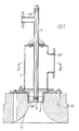
- FIG. 1 As an example of a reheating furnace for iron and steel products, in Figure 1 there is shown a walking beam furnace for reheating slabs B, billets, or the like.
- the invention may be however applied to any other types of reheating furnaces, for example, to pusher furnaces or pit furnaces, and for any other kind of iron and steel products.
- numeral 1 denotes the stationary beams
- numeral 2 denotes the walking beams supported by uprights 3 passed through openings 4 provided in the furnace bottom 5.
- each burner A1, A2 comprises a central fuel pipe 6 opening into an inwardly curved flared portion 17 in the furnace wall.
- the pipe 6 is connected through the pipe fitting 106 to the fuel distribution system, and this pipe is surrounded by a casing 7 for the supply of combustion air.
- the casing 7 is connected through the pipe fitting 107 to the combustion air distribution system, and this casing opens into the inwardly curved flared portion 17 through a diffuser 8 provided around the outlet of the fuel pipe 6.
- the diffuser 8 comprises a circular arrangement of stationary guide vanes 108 which are substantially tangent to the central fuel pipe 6. In the burner type A1 the guide vanes 108 in the diffuser 8 are inclined in one direction, while in the burner type A2 the guide vanes 108 in the diffuser 8 are inclined in the opposite direction.
- the combustion air flowing through the diffuser 8 in the burner type A1 is imparted a rotation in the opposite direction to the rotation of the combustion air flowing through the diffuser 8 in the burner type A2.
- the flame generated by the burner type A1 rotates in one direction, for example, in clockwise direction
- the flame generated by the burner type A2 rotates in the opposite direction, for example, in anticlockwise direction.
- Both types of rotating-flame burners A1, A2 shown in Figures 3, 4 and 5, are operated particularly with gaseous fluid that is also imparted a rotary motion by a helical swirl device 9 provided in the outlet end of the fuel pipe 6.
- the two types of rotating-flame burners A1, A2 can be operated even or only with liquid fuel when a suitable spray nozzle, or the like, is provided at the end of the fuel pipe 6.
- the casing 7 for the supply of combustion air may be set in communication with any other suitable type of diffuser provided around the outlet of the fuel pipe 6, and adapted for imparting a clockwise or anticlockwise rotation to the outflowing combustion air, and so to the generated flame.
- a diffuser of this type may, for example, consist of a plurality of air outflow ports provided in the bottom of the inwardly curved flared portion 17, and inclined in one direction for the burner type A1, and in the opposite direction for the burner type A2.
- a set of burners A1, A2 are provided and arranged in a plurality of parallel rows F1, F2, F3, F4 extending in the longitudinal direction of the furnace 1.
- Each burner row F1, F2, F3, F4 is formed by a succession of the two alternated burner types A1, A2, i.e., by a row of burners A1, A2 having by turns their flames rotating in clockwise and in anticlockwise direction.
- the two alternated types of burners A1, A2 in each row F1, F2, F3, F4 are also offset with respect to the two alternated burner types A1, A2 in the adjacent row or rows, so that at the side of each burner A1 or A2 belonging to one of the rows F1, F2, F3, F4 and having its flame rotating in one direction, for example, in clockwise direction, one or two burners A2 or A1 are located, which belong to the adjacent row or rows, and have their flame rotating in the opposite, for example, anticlockwise direction.
- the furnace C according to Figure 1 may be heated by burners provided on at least one of the two longitudinal sidewalls of the furnace, and/or on at least one of the two transversal endwalls thereof.
- a horizontal row F5 of rotating-flame burners is provided over the beams 1, 2 and then over the slabs B or billets to be reheated, and a horizontal row F6 of rotating-flame burners is provided thereon, under the beams 1, 2 and then under the slabs B or billets to be reheated.
- Each burner row F5, F6 is formed by the above-disclosed two burner types A1, A2, and the flame of one burner type (A1) rotates in clockwise direction, while the flame of the other burner type (A2) rotates in anticlockwise direction.
- each row F5 F6, these two types of burners A1, A2 are alternated, so that on one or both sides of each burner A1 with its flame rotating in clockwise direction, there is placed a burner A2 with its flame rotating in anticlockwise direction, and vice-versa.
- the fluid-dynamic conditions of the combustion air flow and rotation in the two types of rotating-flame burners A1, A2 fitted on the longitudinal sidewall or sidewalls 11 of furnace C, are so selected that these burners will generate a longer or a shorter flame.
- a similar alternated arrangement of burners A1, A2 with their flames rotating in clockwise and in anticlockwise direction, may be provided also on at least one of the transversal endwalls 12 of the furnace C.
Description
- The invention relates to a reheating furnace for iron and steel products, particularly for slabs, billets, and the like. Such a furnace is provided on the furnace roof and/or on at least one of the longitudinal sidewalls and/or transversal endwalls thereof with a plurality of burners having their flame rotating around the central axis of the respective burner.
- The rotating-flame burners for a reheating furnace for iron and steel products are known, for example, from the document DE-A-2 801 367. The flame is rotated by the combustion air flowing around the fuel nozzle and being imparted a rotary motion by suitably inclined means for guiding the combustion air flow, such as inclined guide vanes or inclined ports, or by any other suitable swirl device. The fluid-dynamic conditions of the combustion air flow and speed of rotation may be so selected as to obtain a longer or a shorter rotating flame, or a disc-shaped flat flame.
- Burners with their flame being a flat or a disc-shaped rotating flame, i.e., the so-called radiant burners, are preferably, but not exclusively installed on the roof of a reheating furnace for iron and steel products, and are arranged, for example, in one or more parallel rows extending in the longitudinal direction of the furnace. In the known embodiments, the flames of all the rotating-flame burners fitted on the furnace roof rotate in the same, either clockwise or anticlockwise direction, which results in the following inconveniences.
- Particularly when the rotating-flame burners on the furnace roof are flat-flame burners, these flames bring about a turbulence in the furnace atmosphere only in a limited zone which is near to the furnace roof. In the lower zones of the furnace, and particularly at the level of iron and steel products to be reheated, the turbulence in the furnace atmosphere decreases to an almost zero value, so that the flue gases become stratified, and the vertical exchanges in the furnace atmosphere are sensibly reduced. This determines a deficiency of the oxygen content in the furnace atmosphere, at the level of the iron and steel products to be reheated. The oxygen contained in the furnace atmosphere forms a superficial layer of oxides on the iron and steel products to be reheated. When the oxygen content in the furnace atmosphere at the level of the products to be reheated, has an optimum value, such as, for example, in the order of 1-2%, a layer of oxides is formed on the surface of the reheated iron and steel products, which can be entirely removed in a relatively easy manner. Conversely, when the oxygen content in the furnace atmosphere at the level of the to-be-reheated iron and steel products, goes down below the said optimum value, such as in the case of the said lack of vertical exchanges in the furnace atmosphere, owing to the unidirectional rotation of the flames of all the burners on the furnace roof, a layer of oxides is formed on the surface of the to-be-reheated products, which is thinner, but which is a harder and rather firmly sticking layer. This latter layer of oxides is difficult to be removed, so that on the reheated iron and steel products there is still left a residue of oxides, that gives rise to some inconveniences on the subsequent rolling of the reheated products, and that sensibly lowers the grade of the rolled products.
- Another inconvenience caused by the unidirectional rotation of the flames of the burners set up on the furnace roof, resides in the fact that a unidirectional horizontal circulation of flue gases is thus produced, particularly in the upper part of the furnace. Such a circulation of flue gases consists of a flue gas stream in one direction, close to one longitudinal sidewall of the furnace, and a reversed flue gas stream, i.e., in the opposite direction, close to the other longitudinal sidewall of the furnace. In a furnace in which the products to be reheated are advanced along the furnace, the average flue gas temperature near the wall beside which the flue gases stream horizontally in the direction of the moved forward products to be reheated, is lower than the temperature which is attained near the opposite longitudinal sidewall of the furnace, where the flue gase stream is a reversed stream, which runs in the opposite direction to the moved forward products to be reheated. Such a temperature difference between the two longitudinal sidewalls of the furnace brings about a not uniform heating of the iron and steel products in the furnace, so that some inconveniences aill then arise in the subsequent rolling of said products.
- Burners having a longer or shorter rotating flame are preferably, but non exclusively installed on the longitudinal sidewalls and/or on the transversal endwalls of a furnace for reheating iron and steel products, and are arranged, for example, in at least one horizontal row. Also in this case, in the known embodiments the flames of all the rotating-flame burners fitted on the longitudinal sidewalls and/or transversal endwalls of the furnace rotate in the same, either clockwise or anticlockwise direction, which leads to the following inconveniences.
- The unidirectional rotation of the flame of the burners provided on one or the longitudinal sidewalls of the furnace, produces beside the respective wall a stable vertical circulation of flue gases, with a horizontal flue gas stream in one direction under the burner row or rows, and with a reversed horizontal stream in the opposite direction over the burner row or rows. Such a flue gas circulation brings about an undesired not uniform distribution of pressure in the inside of the furnace, so that difficulties are encountered in the control of said pressure. Moreover, the said vertical circulation of flue gases along one of the longitudinal sidewalls of the furnace gives rise in a furnace provided with a chimney at either ends thereof, to a sensibly unbalanced distribution of flue gases between the two chimneys, which involves a considerable lowering of the furnace efficiency, since the two heat recuperators associated with the two chimneys are operating respectively at a lower and at a higher flue gas outflow rate than their established rate.
- Another inconvenience arising from the unidirectional rotation of the flames of the burners fitted on one of the longitudinal sidewalls of the furnace, and from the resulting vertical circulation of flue gases, resides in the not uniform temperature distribution, which is due to the inevitable inleakage of cold air through the several indispensable openings in the furnace hearth. Such a cold air inleakage is sucked by, and taken in the flue gas stream which has formed beside the one longitudinal sidewall under the burner row or rows, as a result of the vertical flue gas circulation produced by the unidirectional rotation of the burner flames. Therefore, under the rotating flame burner row or rows a temperature drop occurs on the one longitudinal sidewall of the furnace, and so the respective ends of the to-be-heated iron and steel products are colder.
- The said not uniform distribution of temperature is of a higher degree in a bilaterally heated furnace, when at least one row of rotating-flame burners are provided on both of the longitudinal sidewalls of the furnace. In this case, burners of the same type, i.e. with their flame rotating in the same, either clockwise or anticlockwise direction, are used in a known furnace for both of the longitudinal sidewalls of the furnace. Consequently, on the two facing longitudinal sidewalls of the furnace vertically circulating currents will be generated, which rotate in the same, either clockwise or anticlockwise direction, while their horizontal streams which have formed under a row or under respective rows of burners, and which take in any cold air inleakage from below, run in opposite directions. The temperature drop under the burner row or rows then occurs at both longitudinal sidewalls of the furnace and, particularly in the reheating furnaces for slabs or billets extending transversely to the furnace throughout its length, leads to a correspondingly lower heating of both of the slabs or billets ends. Such an uneven heating of slabs or billets gives rise to difficulties in the subsequent rolling of the same, due to their not uniform hardness.
- The known installation of two or more superposed, side by side burners with their flames rotating in the same direction, on one or both of the transversal endwalls of the furnace gives rise to inconveniences which are similar to the above disclosed inconveniences.
- The object of the invention is to eliminate the above disclosed inconveniences in the known furnaces, and this object is achieved by the provision in a furnace of the type as described in the preamble and of two different types of burners, one burner type with the flame rotating in clockwise direction, and the other burner type with the flame rotating in anticlockwise direction. In a particularly advantageous embodiment of the invention, the flames of at least two adjacent burners rotate in opposite directions. When the burners are arranged in one or more rows, the burners in each row alternately have their flames rotating in opposite directions. When the burners are arranged in one or more parallel rows, each burner belonging to one row and having its flame rotating in one direction, is located at the side of a burner belonging to an adjacent row and having its flame rotating in the opposite direction. Irrespective of the arrangement of the burners, it is generally aimed at having each burner with its flame rotating in one direction, at least partly encircled by burners with their flames rotating in the opposite direction.
- The rotation in opposite directions of the flames of the burners in a furnace according to the invention can be achieved by means of any suitable means. Preferably, however, in one embodiment of the two burner types in the furnace according to the invention, the means for guiding the combustion air flow, which, for example, consist of inclined guide vanes or inclined ports, are inclined in opposite directions.
- One embodiment is shown by way of a non-limiting example in the drawings, in which:
- Figure 1 is a vertical sectional view diagrammatically showing a reheating furnace for slabs or billets.
- Figure 2 is a view from below in an enlarged scale, showing part of the roof of the furnace according to Figure 1.
- Figure 3 is a longitudinal sectional view showing one embodiment of a rotating-flame burner.
- Figures 4 and 5 are cross-sectional views on line IV-IV in Figure 3, showing the two types of burners, one burner type with the flame rotating in clockwise direction, and the other burner type with the flame rotating in anticlockwise direction, which are used in the furnace according to Figures 1 and 2.
- As an example of a reheating furnace for iron and steel products, in Figure 1 there is shown a walking beam furnace for reheating slabs B, billets, or the like. The invention may be however applied to any other types of reheating furnaces, for example, to pusher furnaces or pit furnaces, and for any other kind of iron and steel products.
- The construction and the operation of a reheating walking beam furnace are well known to those skilled in the art, and so the disclosure thereof is omitted. In Figure 1 numeral 1 denotes the stationary beams, and numeral 2 denotes the walking beams supported by uprights 3 passed through
openings 4 provided in thefurnace bottom 5. - To heat the furnace C according to Figure 1, use is made of two types of rotating-flame burners A1 and A2, i.e., one burner type A1 with the flame rotating in one direction, for example, in clockwise direction, and one burner type A2 with the flame rotating in the opposite direction, for example, in anticlockwise direction. One possible embodiment of these two types of burners A1 and A2 is shown in Figures 3, 4 and 5. The longitudinal section shown in Figure 3 is common to both types of burners A1, A2, while the two cross-sections shown in Figures 4 and 5 illustrate the differences between the burners A1 and A2. Each burner A1, A2 comprises a central fuel pipe 6 opening into an inwardly curved flared
portion 17 in the furnace wall. The pipe 6 is connected through the pipe fitting 106 to the fuel distribution system, and this pipe is surrounded by a casing 7 for the supply of combustion air. The casing 7 is connected through the pipe fitting 107 to the combustion air distribution system, and this casing opens into the inwardly curved flaredportion 17 through a diffuser 8 provided around the outlet of the fuel pipe 6. The diffuser 8 comprises a circular arrangement ofstationary guide vanes 108 which are substantially tangent to the central fuel pipe 6. In the burner type A1 theguide vanes 108 in the diffuser 8 are inclined in one direction, while in the burner type A2 theguide vanes 108 in the diffuser 8 are inclined in the opposite direction. Therefore, the combustion air flowing through the diffuser 8 in the burner type A1 is imparted a rotation in the opposite direction to the rotation of the combustion air flowing through the diffuser 8 in the burner type A2. Thus, also the flame generated by the burner type A1 rotates in one direction, for example, in clockwise direction, while the flame generated by the burner type A2 rotates in the opposite direction, for example, in anticlockwise direction. - Both types of rotating-flame burners A1, A2 shown in Figures 3, 4 and 5, are operated particularly with gaseous fluid that is also imparted a rotary motion by a
helical swirl device 9 provided in the outlet end of the fuel pipe 6. Numerous changes and modifications are however possible. Particularly, the two types of rotating-flame burners A1, A2 can be operated even or only with liquid fuel when a suitable spray nozzle, or the like, is provided at the end of the fuel pipe 6. Moreover, the casing 7 for the supply of combustion air may be set in communication with any other suitable type of diffuser provided around the outlet of the fuel pipe 6, and adapted for imparting a clockwise or anticlockwise rotation to the outflowing combustion air, and so to the generated flame. A diffuser of this type may, for example, consist of a plurality of air outflow ports provided in the bottom of the inwardly curved flaredportion 17, and inclined in one direction for the burner type A1, and in the opposite direction for the burner type A2. - On the
roof 10 of the reheating furnace C according to Figure 1 a set of burners A1, A2 are provided and arranged in a plurality of parallel rows F1, F2, F3, F4 extending in the longitudinal direction of the furnace 1. Each burner row F1, F2, F3, F4 is formed by a succession of the two alternated burner types A1, A2, i.e., by a row of burners A1, A2 having by turns their flames rotating in clockwise and in anticlockwise direction. The two alternated types of burners A1, A2 in each row F1, F2, F3, F4 are also offset with respect to the two alternated burner types A1, A2 in the adjacent row or rows, so that at the side of each burner A1 or A2 belonging to one of the rows F1, F2, F3, F4 and having its flame rotating in one direction, for example, in clockwise direction, one or two burners A2 or A1 are located, which belong to the adjacent row or rows, and have their flame rotating in the opposite, for example, anticlockwise direction. Thus, for the set of rotating-flame burners provided on theroof 10 of the reheating furnace C, a quincuncial arrangement is obtained of the two types of burners A1 and A2, with their flames rotating in clockwise and in anticlockwise direction, as it clearly appears particularly in Figure 2. Preferably, the fluid-dynamic conditions of the combustion air flow and rotation in the two types of rotating-flame burners A1, A2 provided on theroof 10 of furnace C, are so selected that these burners A1, A2 will generate a disc-shaped flat flame, i.e., the same are burners of the so-called radiant type. - By the said alternated arrangement of the two types of burners A1, A2 with their flames rotating in opposite directions on the
roof 10 of furnace C, surprisingly a plurality of downward vertical streams will be formed, which prevent the flue gases from becoming stratified, and which eliminate or at least sensibly reduce any difference in the chemical composition of the upper and the lower part of the atmosphere in the furnace C. Thus it is also avoided that the oxygen content in the atmosphere of the furnace at the level of the slabs B or billets to be reheated may become poor, whereby any inconvenience brought about by such a poor oxygen content, as disclosed in the introduction to the specification, is eliminated. Moreover, the forming of a unidirectional horizontal circulation of flue gases in the furnace C is prevented, so that a temperature difference between the two longitudinal sidewalls of the furnace is avoided. Therefore, a uniform temperature of flue gases is ensured throughout the hollow space in furnace C, which etermines a correspondingly uniform heating of slabs B or billets. In combination with the above disclosed set of rotating-flame, preferably flat-flame burners A1, A2 provided on theroof 10 of furnace C, or in place of the said set of burners, the furnace C according to Figure 1 may be heated by burners provided on at least one of the two longitudinal sidewalls of the furnace, and/or on at least one of the two transversal endwalls thereof. In the shown embodiment, on at least one of the twolongitudinal sidewalls 11 of furnace C, a horizontal row F5 of rotating-flame burners is provided over the beams 1, 2 and then over the slabs B or billets to be reheated, and a horizontal row F6 of rotating-flame burners is provided thereon, under the beams 1, 2 and then under the slabs B or billets to be reheated. Each burner row F5, F6 is formed by the above-disclosed two burner types A1, A2, and the flame of one burner type (A1) rotates in clockwise direction, while the flame of the other burner type (A2) rotates in anticlockwise direction. In each row F5, F6, these two types of burners A1, A2 are alternated, so that on one or both sides of each burner A1 with its flame rotating in clockwise direction, there is placed a burner A2 with its flame rotating in anticlockwise direction, and vice-versa. The fluid-dynamic conditions of the combustion air flow and rotation in the two types of rotating-flame burners A1, A2 fitted on the longitudinal sidewall or sidewalls 11 of furnace C, are so selected that these burners will generate a longer or a shorter flame. - With the said alternated arrangement of the two types of burners A1, A2 with their flames rotating in opposite directions, instead of one vertically circulating stream, a plurality of local vertical streams are generated on at least one of the longitudinal sidewalls of the
furnace 11, along the respectivelongitudinal sidewall 11 of the furnace, and are alternatingly directed downwardly and upwardly, so that they make both the pressure and temperature distribution uniform, whereby the inconveniences as disclosed in the introduction to the specification are eliminated. - A similar alternated arrangement of burners A1, A2 with their flames rotating in clockwise and in anticlockwise direction, may be provided also on at least one of the
transversal endwalls 12 of the furnace C.
Claims (7)
- A reheating furnace (C) for iron and steel products, particularly for slabs (B), billets, and the like, provided on the furnace roof (10) and/or on at least one of the longitudinal sidewalls (11) and/or transversal endwalls (12) thereof with a plurality of burners (A1, A2) having their flame rotating around the central axis of the respective burner, characterized in that it is provided with two different burner types (A1, A2), one burner type (A1) having the flame rotating in clockwise direction, and the other burner type (A2) having the flame rotating in anticlockwise direction.
- The furnace according to claim 1, characterized in that the flames of at least two adjacent burners (A1, A2) rotate in opposite directions.
- The furnace according to claim 1, characterized in that when the burners (A1, A2) are arranged in one or more rows (F1, F2, F3, F4, F5, F6), the burners (A1, A2) in each row have by turns their flames rotating in opposite directions.
- The furnace according to claim 1, characterized in that when the burners (A1, A2) are arranged in two or more parallel rows (F1, F2, F3, F4), at the side of each burner (A1 or A2) belonging to one row and having its flame rotating in one direction, a burner (A2 or A1) is located, which belongs to an adjacent row and has its flame rotating in the opposite direction.
- The furnace according to claim 1, characterized in that each burner (A1 or A2) with its flame rotating in one direction, is at least partly encircled by burners (A2 or A1) with their flames rotating in the opposite direction.
- The furnace according to claim 1, characterized by a quincuncial arrangement of burners (A1, A2) with their flames rotating in opposite directions.
- The furnace according to claim 1, characterized in that in the two burner types (A1, A2) the means for guiding the combustion air flow are inclined in opposite directions.
Priority Applications (1)
| Application Number | Priority Date | Filing Date | Title |
|---|---|---|---|
| AT88105593T ATE68528T1 (en) | 1987-04-16 | 1988-04-08 | REHEATING FURNACE WITH ROTATING FLAME BURNERS FOR SLABS AND BLOCKS. |
Applications Claiming Priority (4)
| Application Number | Priority Date | Filing Date | Title |
|---|---|---|---|
| IT8712465A IT1208279B (en) | 1987-04-16 | 1987-04-16 | Reheat furnace with rotating flame burners |
| IT1246587 | 1987-04-16 | ||
| IT1258787 | 1987-11-26 | ||
| IT8712587A IT1213939B (en) | 1987-11-26 | 1987-11-26 | Reheat furnace with rotating flame burners |
Publications (2)
| Publication Number | Publication Date |
|---|---|
| EP0286984A1 EP0286984A1 (en) | 1988-10-19 |
| EP0286984B1 true EP0286984B1 (en) | 1991-10-16 |
Family
ID=26326530
Family Applications (1)
| Application Number | Title | Priority Date | Filing Date |
|---|---|---|---|
| EP19880105593 Expired EP0286984B1 (en) | 1987-04-16 | 1988-04-08 | Reheating furnace with rotating flame burners for slabs and billets |
Country Status (5)
| Country | Link |
|---|---|
| EP (1) | EP0286984B1 (en) |
| BR (1) | BR8801816A (en) |
| CA (1) | CA1294126C (en) |
| DE (1) | DE3865493D1 (en) |
| ES (1) | ES2025720T3 (en) |
Cited By (1)
| Publication number | Priority date | Publication date | Assignee | Title |
|---|---|---|---|---|
| DE19706351B4 (en) * | 1996-02-27 | 2010-04-15 | Sacmi Forni S.P.A. | Single-layer kiln for tiles |
Families Citing this family (2)
| Publication number | Priority date | Publication date | Assignee | Title |
|---|---|---|---|---|
| ITMO20030218A1 (en) * | 2003-07-25 | 2005-01-26 | Tck Societa A Responsabilita Li Mitata | CONTROL SYSTEM OF A CERAMIC OVEN. |
| SE535197C2 (en) * | 2010-09-30 | 2012-05-15 | Linde Ag | Procedure for combustion in an industrial furnace |
Family Cites Families (3)
| Publication number | Priority date | Publication date | Assignee | Title |
|---|---|---|---|---|
| FR1432434A (en) * | 1965-05-10 | 1966-03-18 | Armco Steel Corp | Method and furnace for heating metal parts |
| DE2202115A1 (en) * | 1971-02-02 | 1972-08-10 | British Steel Corp | Method and device for heating strip material |
| DD237771A3 (en) * | 1983-09-23 | 1986-07-30 | Rohrkombinat Stahl & Walzwerk | LARGE-FORMED RADIATION ELEMENT FOR INDUSTRIAL OVEN |
-
1988
- 1988-04-08 DE DE8888105593T patent/DE3865493D1/en not_active Expired - Lifetime
- 1988-04-08 EP EP19880105593 patent/EP0286984B1/en not_active Expired
- 1988-04-08 ES ES88105593T patent/ES2025720T3/en not_active Expired - Lifetime
- 1988-04-12 CA CA000563951A patent/CA1294126C/en not_active Expired - Fee Related
- 1988-04-15 BR BR8801816A patent/BR8801816A/en not_active IP Right Cessation
Cited By (1)
| Publication number | Priority date | Publication date | Assignee | Title |
|---|---|---|---|---|
| DE19706351B4 (en) * | 1996-02-27 | 2010-04-15 | Sacmi Forni S.P.A. | Single-layer kiln for tiles |
Also Published As
| Publication number | Publication date |
|---|---|
| DE3865493D1 (en) | 1991-11-21 |
| BR8801816A (en) | 1988-11-16 |
| ES2025720T3 (en) | 1992-04-01 |
| EP0286984A1 (en) | 1988-10-19 |
| CA1294126C (en) | 1992-01-14 |
Similar Documents
| Publication | Publication Date | Title |
|---|---|---|
| CA1088747A (en) | Preheating furnace | |
| US5934899A (en) | In-line method of burner firing and NOx emission control for glass melting | |
| JPH07196324A (en) | Glass melting furnace and its usage | |
| US4490107A (en) | Method of processing charges in a continuous combustion furnace | |
| JPS639002B2 (en) | ||
| EP0286984B1 (en) | Reheating furnace with rotating flame burners for slabs and billets | |
| US3854865A (en) | Kiln for ceramic products | |
| CA1171660A (en) | Regenerator flow distribution by means of air jets | |
| US4444557A (en) | Continuous combustion furnace | |
| CA1151420A (en) | Method and apparatus for the ignition of a solid fuel and a sinterable mixture | |
| US4388068A (en) | Metal heating furnace | |
| US3550918A (en) | Heat regenerator,particularly a regenerative air preheater for a blast furnace | |
| EP0453696B2 (en) | A tunnel kiln | |
| US4334861A (en) | Method and apparatus for generating a hot air blast | |
| US2262609A (en) | Furnace for coating baths | |
| US3411761A (en) | Burner and soaking pit | |
| US4435152A (en) | Apparatus for improving the flow of gases to a combustion chamber of a coke oven or the like | |
| CN102869797B (en) | Improve the method for temperature homogeneity in pit furnace | |
| JPH08291328A (en) | Continuous heating apparatus | |
| US1719452A (en) | Soaking pit | |
| US2257392A (en) | Regenerative furnace | |
| US2079560A (en) | Recuperative soaking pit furnace | |
| SU1295181A1 (en) | Fast heating furnace | |
| SU759822A1 (en) | Conveyer furnace | |
| RU2114185C1 (en) | Reheating walking-beam furnace for heating of long metal articles |
Legal Events
| Date | Code | Title | Description |
|---|---|---|---|
| PUAI | Public reference made under article 153(3) epc to a published international application that has entered the european phase |
Free format text: ORIGINAL CODE: 0009012 |
|
| AK | Designated contracting states |
Kind code of ref document: A1 Designated state(s): AT BE CH DE ES FR GB GR IT LI LU NL SE |
|
| 17P | Request for examination filed |
Effective date: 19890404 |
|
| 17Q | First examination report despatched |
Effective date: 19901129 |
|
| GRAA | (expected) grant |
Free format text: ORIGINAL CODE: 0009210 |
|
| AK | Designated contracting states |
Kind code of ref document: B1 Designated state(s): AT BE CH DE ES FR GB GR IT LI LU NL SE |
|
| PG25 | Lapsed in a contracting state [announced via postgrant information from national office to epo] |
Ref country code: IT Free format text: LAPSE BECAUSE OF FAILURE TO SUBMIT A TRANSLATION OF THE DESCRIPTION OR TO PAY THE FEE WITHIN THE PRE;WARNING: LAPSES OF ITALIAN PATENTS WITH EFFECTIVE DATE BEFORE 2007 MAY HAVE OCCURRED AT ANY TIME BEFORE 2007. THE CORRECT EFFECTIVE DATE MAY BE DIFFERENT FROM THE ONE RECORDED.SCRIBED TIME-LIMIT Effective date: 19911016 Ref country code: LI Effective date: 19911016 Ref country code: CH Effective date: 19911016 Ref country code: GR Free format text: LAPSE BECAUSE OF FAILURE TO SUBMIT A TRANSLATION OF THE DESCRIPTION OR TO PAY THE FEE WITHIN THE PRESCRIBED TIME-LIMIT Effective date: 19911016 |
|
| REF | Corresponds to: |
Ref document number: 68528 Country of ref document: AT Date of ref document: 19911115 Kind code of ref document: T |
|
| REF | Corresponds to: |
Ref document number: 3865493 Country of ref document: DE Date of ref document: 19911121 |
|
| ET | Fr: translation filed | ||
| REG | Reference to a national code |
Ref country code: CH Ref legal event code: PL |
|
| REG | Reference to a national code |
Ref country code: ES Ref legal event code: FG2A Ref document number: 2025720 Country of ref document: ES Kind code of ref document: T3 |
|
| PLBE | No opposition filed within time limit |
Free format text: ORIGINAL CODE: 0009261 |
|
| STAA | Information on the status of an ep patent application or granted ep patent |
Free format text: STATUS: NO OPPOSITION FILED WITHIN TIME LIMIT |
|
| 26N | No opposition filed | ||
| EPTA | Lu: last paid annual fee | ||
| EAL | Se: european patent in force in sweden |
Ref document number: 88105593.3 |
|
| PGFP | Annual fee paid to national office [announced via postgrant information from national office to epo] |
Ref country code: GB Payment date: 19960328 Year of fee payment: 9 |
|
| PG25 | Lapsed in a contracting state [announced via postgrant information from national office to epo] |
Ref country code: GB Effective date: 19970408 |
|
| GBPC | Gb: european patent ceased through non-payment of renewal fee |
Effective date: 19970408 |
|
| PGFP | Annual fee paid to national office [announced via postgrant information from national office to epo] |
Ref country code: AT Payment date: 19990430 Year of fee payment: 12 |
|
| PG25 | Lapsed in a contracting state [announced via postgrant information from national office to epo] |
Ref country code: AT Free format text: LAPSE BECAUSE OF NON-PAYMENT OF DUE FEES Effective date: 20000408 |
|
| PGFP | Annual fee paid to national office [announced via postgrant information from national office to epo] |
Ref country code: NL Payment date: 20070403 Year of fee payment: 20 |
|
| PGFP | Annual fee paid to national office [announced via postgrant information from national office to epo] |
Ref country code: SE Payment date: 20070404 Year of fee payment: 20 |
|
| PGFP | Annual fee paid to national office [announced via postgrant information from national office to epo] |
Ref country code: DE Payment date: 20070405 Year of fee payment: 20 |
|
| PGFP | Annual fee paid to national office [announced via postgrant information from national office to epo] |
Ref country code: LU Payment date: 20070412 Year of fee payment: 20 |
|
| PGFP | Annual fee paid to national office [announced via postgrant information from national office to epo] |
Ref country code: ES Payment date: 20070521 Year of fee payment: 20 |
|
| PGFP | Annual fee paid to national office [announced via postgrant information from national office to epo] |
Ref country code: BE Payment date: 20070612 Year of fee payment: 20 |
|
| BE20 | Be: patent expired |
Owner name: *ITALIMPIANTI SOCIETA ITALIANA IMPIANTI P.A. Effective date: 20080408 |
|
| PGFP | Annual fee paid to national office [announced via postgrant information from national office to epo] |
Ref country code: FR Payment date: 20070411 Year of fee payment: 20 |
|
| PG25 | Lapsed in a contracting state [announced via postgrant information from national office to epo] |
Ref country code: NL Free format text: LAPSE BECAUSE OF EXPIRATION OF PROTECTION Effective date: 20080408 |
|
| NLV7 | Nl: ceased due to reaching the maximum lifetime of a patent |
Effective date: 20080408 |
|
| EUG | Se: european patent has lapsed | ||
| REG | Reference to a national code |
Ref country code: ES Ref legal event code: FD2A Effective date: 20080409 |
|
| PG25 | Lapsed in a contracting state [announced via postgrant information from national office to epo] |
Ref country code: ES Free format text: LAPSE BECAUSE OF EXPIRATION OF PROTECTION Effective date: 20080409 |