EP0286865B1 - Helical band drive for disc storage apparatus - Google Patents
Helical band drive for disc storage apparatus Download PDFInfo
- Publication number
- EP0286865B1 EP0286865B1 EP88104344A EP88104344A EP0286865B1 EP 0286865 B1 EP0286865 B1 EP 0286865B1 EP 88104344 A EP88104344 A EP 88104344A EP 88104344 A EP88104344 A EP 88104344A EP 0286865 B1 EP0286865 B1 EP 0286865B1
- Authority
- EP
- European Patent Office
- Prior art keywords
- pulley
- bands
- band
- shaft
- drive
- Prior art date
- Legal status (The legal status is an assumption and is not a legal conclusion. Google has not performed a legal analysis and makes no representation as to the accuracy of the status listed.)
- Expired - Lifetime
Links
Images

Classifications
-
- G—PHYSICS
- G11—INFORMATION STORAGE
- G11B—INFORMATION STORAGE BASED ON RELATIVE MOVEMENT BETWEEN RECORD CARRIER AND TRANSDUCER
- G11B5/00—Recording by magnetisation or demagnetisation of a record carrier; Reproducing by magnetic means; Record carriers therefor
- G11B5/48—Disposition or mounting of heads or head supports relative to record carriers ; arrangements of heads, e.g. for scanning the record carrier to increase the relative speed
- G11B5/54—Disposition or mounting of heads or head supports relative to record carriers ; arrangements of heads, e.g. for scanning the record carrier to increase the relative speed with provision for moving the head into or out of its operative position or across tracks
- G11B5/55—Track change, selection or acquisition by displacement of the head
-
- H—ELECTRICITY
- H02—GENERATION; CONVERSION OR DISTRIBUTION OF ELECTRIC POWER
- H02K—DYNAMO-ELECTRIC MACHINES
- H02K7/00—Arrangements for handling mechanical energy structurally associated with dynamo-electric machines, e.g. structural association with mechanical driving motors or auxiliary dynamo-electric machines
- H02K7/06—Means for converting reciprocating motion into rotary motion or vice versa
-
- F—MECHANICAL ENGINEERING; LIGHTING; HEATING; WEAPONS; BLASTING
- F16—ENGINEERING ELEMENTS AND UNITS; GENERAL MEASURES FOR PRODUCING AND MAINTAINING EFFECTIVE FUNCTIONING OF MACHINES OR INSTALLATIONS; THERMAL INSULATION IN GENERAL
- F16H—GEARING
- F16H19/00—Gearings comprising essentially only toothed gears or friction members and not capable of conveying indefinitely-continuing rotary motion
- F16H19/02—Gearings comprising essentially only toothed gears or friction members and not capable of conveying indefinitely-continuing rotary motion for interconverting rotary or oscillating motion and reciprocating motion
- F16H19/06—Gearings comprising essentially only toothed gears or friction members and not capable of conveying indefinitely-continuing rotary motion for interconverting rotary or oscillating motion and reciprocating motion comprising flexible members, e.g. an endless flexible member
- F16H19/0622—Gearings comprising essentially only toothed gears or friction members and not capable of conveying indefinitely-continuing rotary motion for interconverting rotary or oscillating motion and reciprocating motion comprising flexible members, e.g. an endless flexible member for converting reciprocating movement into oscillating movement and vice versa, the reciprocating movement is perpendicular to the axis of oscillation
-
- G—PHYSICS
- G11—INFORMATION STORAGE
- G11B—INFORMATION STORAGE BASED ON RELATIVE MOVEMENT BETWEEN RECORD CARRIER AND TRANSDUCER
- G11B5/00—Recording by magnetisation or demagnetisation of a record carrier; Reproducing by magnetic means; Record carriers therefor
- G11B5/48—Disposition or mounting of heads or head supports relative to record carriers ; arrangements of heads, e.g. for scanning the record carrier to increase the relative speed
- G11B5/54—Disposition or mounting of heads or head supports relative to record carriers ; arrangements of heads, e.g. for scanning the record carrier to increase the relative speed with provision for moving the head into or out of its operative position or across tracks
- G11B5/55—Track change, selection or acquisition by displacement of the head
- G11B5/5521—Track change, selection or acquisition by displacement of the head across disk tracks
-
- H—ELECTRICITY
- H02—GENERATION; CONVERSION OR DISTRIBUTION OF ELECTRIC POWER
- H02K—DYNAMO-ELECTRIC MACHINES
- H02K7/00—Arrangements for handling mechanical energy structurally associated with dynamo-electric machines, e.g. structural association with mechanical driving motors or auxiliary dynamo-electric machines
- H02K7/10—Structural association with clutches, brakes, gears, pulleys or mechanical starters
- H02K7/1004—Structural association with clutches, brakes, gears, pulleys or mechanical starters with pulleys
-
- Y—GENERAL TAGGING OF NEW TECHNOLOGICAL DEVELOPMENTS; GENERAL TAGGING OF CROSS-SECTIONAL TECHNOLOGIES SPANNING OVER SEVERAL SECTIONS OF THE IPC; TECHNICAL SUBJECTS COVERED BY FORMER USPC CROSS-REFERENCE ART COLLECTIONS [XRACs] AND DIGESTS
- Y10—TECHNICAL SUBJECTS COVERED BY FORMER USPC
- Y10T—TECHNICAL SUBJECTS COVERED BY FORMER US CLASSIFICATION
- Y10T74/00—Machine element or mechanism
- Y10T74/18—Mechanical movements
- Y10T74/18568—Reciprocating or oscillating to or from alternating rotary
- Y10T74/18832—Reciprocating or oscillating to or from alternating rotary including flexible drive connector [e.g., belt, chain, strand, etc.]
Definitions
- the subject invention relates generally to a head positioning assembly for disc drive apparatus and more particularly to a band drive for use in either a linear or rotary positioning assembly.
- Disc drive machines record and reproduce information stored on concentric circular tracks on magnetic discs. Tracks are written and read by magnetic heads which cooperate with the surface of the disc.
- Various methods have been used to position the head; The two common types of data accessing mechanisms are linear and rotary head carriages. In both types, the objective is to position a magnetic head over a concentric track on the surface of a magnetic disc for reading or writing of information.
- Band drives are shown and described in U.S. Patent 4,161,004, and 4,170,146 among others. These drives convert rotary motion of a stepper motor shaft to motion of the carriage to move the heads mounted on the carriage across the disc to record and read adjacent concentric circular tracks.
- a typical drive band is wrapped around the motor shaft or a pulley attached to the shaft, and has its ends attached to the carriage so that rotation of the shaft wraps one portion of the band on the pulley while unwrapping the other, causing the carriage to move.
- a new track is recorded at each step of the stepper motor as it moves the head across the disc.
- an object of the invention is to provide a band drive design which reduces or eliminates instantaneous changes in stress on the band.
- This invention provides a positioning apparatus for movably controlling the position of a component between first and second positions, the component being supported for movement between said first and second positions, the apparatus comprising a drive means including a drive motor having a rotatable shaft, a pulley carried on said shaft, and first and second separate parallel bands, one end of each of said bands being fastened to said component and the other end of each said bands being connected to said pulley whereby rotation of said shaft wraps one and unwraps the other band on said pulley to displace the component between said first and second positions; wherein the bands are wrapped helically on said pulley each defining an acute angle with the axis of rotation of the pulley on the drive means with one band wrapping onto a portion of the pulley surface area adjacent to the pulley portion left vacant by the unwrapping of the other band the arrangement permitting the pulley to rotate for at least 360 and enabling the length of the pulley in the direction of the axis to be minimised.
- a drive means including
- said drive motor is positioned with said drive shaft perpendicular to said recording medium and the direction of travel of said carriage and is adapted to rotate 360 or more to extend the length of the path of travel of the carriage.
- stepper motor is allowed to make more than one complete revolution in moving a recording head from track to track in a disc drive, thereby increasing the number of tracks which may be addressed, or, depending on the application, increasing the spacing between the tracks if such is desirable.
- said first and second bands may be fastened to opposite ends of the pulley, one of said bands being helically wrapped on said pulley surface area towards the centre of said pulley depending on the direction of rotation of said pulley simultaneously with the unwrapping of the other band from said pulley, the centre lines of each of said bands lying substantially in parallel along the carriage.
- GB-A-1192623 discloses a disc scanning apparatus including a transducer carrying sector shaped plate having an outwardly facing curved wall. The plate is mounted at one corner for pivotal movement about an axis parallel to the disc axis. A motor driven band encircles the sector plate and thereby positions the transducer relative to the disc.
- the present invention also provides a positioning apparatus for positioning a magnetic head relative to a recording medium, the apparatus including a head carrying mechanism mounted for rotary movement over said recording medium, a drive arm connected to the head carrying mechanism and rotatable about a pivot point, the distal end of said arm from said pivot point mounting a curved end portion, drive means for rotating said drive arm comprising a drive motor having a drive shaft extending perpendicular to said recording medium and the direction of travel of the head carrying mechanism, said drive shaft being mounted just outside the arc of the circle along which said curved end portion travels and being connected to said end portion for causing movement thereof by flexible band means comprising first and second distinct parallel bands, each having one end connected to said shaft and the other end connected to said end portion of said arm, said bands being wound on and unwound from said shaft for moving said head carrying mechanism; wherein the bands are wound helically on the shaft wrapping on the same angular cross section of a surface area of the shaft with one band wrapping on to a portion of the shaft surface area adjacent to the
- Figure 1 shows the basic elements of a linear disc drive head actuator including a stepper motor 6 having a drive shaft 12, a pulley 13 carried at the end of the drive shaft and adapted to receive a drive band 14 and a carriage 17.
- the band includes a first portion 14A and a second portion 14B each secured by a screw 18A,18B to a distant end of the carriage 17 and by a screw or other fastener 20A,20B to the drive shaft.
- Rotation of the drive shaft 12 and pulley 13 clockwise or counter-clockwise winds and unwinds the first and second band portions 14A,14B on the pulley to move the carriage.
- the carriage includes cut-out portions 17a,17b to allow the drive shaft securing screws or fasteners 20a and 20b to rotate past the plane of the carriage.
- the carriage itself mounts an E-shaped or other suitable mount 32 for a plurality of heads 33 which are adapted to cooperate with one or more associated discs.
- the carriage which in this embodiment is a linear carriage, moves linearly along a track to move the heads in and out on the surface of the associated disc to read and write information on the disc surface.
- the band portions 14A, 14B helically wind on portions of the pulley 13, thus each band can wind around more than one complete revolution of the pulley, the stepper motor is capable of more than one complete revolution.
- the band portion being wound on the pulley is wound on substantially the same pulley surface area as the other pulley has just been unwound from.
- the carriage can be moved a greater distance, allowing for an increased number of tracks to be defined. This is a highly significant advantage in a technology where increased data storage is of critical importance.
- figure 4A depicts the average stress level imposed on a normally wound split band as is now in common use, and particularly the instantaneous change in stress on the band at the point 100 where the band comes in contact with the pulley.
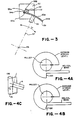
- Figure 3 shown therein are the pertinent portions of a rotary actuator embodying the present invention.
- Figure 3 demonstrates the means for converting the rotary motion of a stepper motor to rotary motion of a mechanical arm, which can then be used to position a head carrying mechanism.
- Omitted from Figure 3 is the actual head carrying mechanism, which can be embodied in various ways known to anyone familiar with the art.
- Figure 3 shows a stepper motor 50 having a rotatable shaft 51 on which is mounted a pulley 52.
- a rotating arm (shown partially at 56) extends along line 57 to pivot point 58.
- a curved end portion 59 whose radius is the distance from pivot point 58 to a point closely adjacent to the pulley 52.
- Connecting the pulley 52 to the curved end portion 59 of arm 56 are two helically wound band segments 53A and 53B.
- One end of each of the band segments 53A, 53B is secured to the ends of the curved end portion 59 of arm 56 by screws or other appropriate fasteners 54A, 54B.
- band segments 53A, 53B are secured to the pulley 52 by screws or other appropriate fasteners 55A, 55B.
- stepper motor 50 rotates the shaft 51 and attached pulley 52 clockwise or counterclockwise, the band segments 53A, 53B are wound on and unwound from pulley 52 rotating the arm 56 along path "A".
- the curved end portion 59 of the arm 56 is notched, as shown previously in Figure 2, to allow clearance for fasteners 55A, 55B, and supports the unwound portions of the band segments 53A, 53B.
- the distance that the arm 56 moves along path "A" with each step of the motor 50 is determined by several factors: a) the amount of rotation the motor makes with each step, b) the diameter of the pulley 52, and the length of the arm 56.
- the total portion of the circular path "A" through which the arm 56 can rotate is dependent only on the length of the band segments 53A, 53B and the length of the curved end portion 59 of the arm 56, since the helically wound band segments allow the pulley to rotate through more than 360 °.
- a positioning assembly has been provided which is especially useful in a disc drive or the like.
- Use of this invention provides for an increased number of tracks being recorded on the disc, and for highly accurate positioning of the head in movement across the disc. Further, the life of any machine incorporating this helical band drive is lengthened due to reduced exposure of the band to instantaneous changes in stress.
Landscapes
- Engineering & Computer Science (AREA)
- General Engineering & Computer Science (AREA)
- Power Engineering (AREA)
- Mechanical Engineering (AREA)
- Moving Of Heads (AREA)
Description
- The subject invention relates generally to a head positioning assembly for disc drive apparatus and more particularly to a band drive for use in either a linear or rotary positioning assembly.
- Disc drive machines record and reproduce information stored on concentric circular tracks on magnetic discs. Tracks are written and read by magnetic heads which cooperate with the surface of the disc. Various methods have been used to position the head; The two common types of data accessing mechanisms are linear and rotary head carriages. In both types, the objective is to position a magnetic head over a concentric track on the surface of a magnetic disc for reading or writing of information.
- Various methods have been used to move the carriage and position the head including lead screws, cams and band drives. Band drives are shown and described in U.S. Patent 4,161,004, and 4,170,146 among others. These drives convert rotary motion of a stepper motor shaft to motion of the carriage to move the heads mounted on the carriage across the disc to record and read adjacent concentric circular tracks. A typical drive band is wrapped around the motor shaft or a pulley attached to the shaft, and has its ends attached to the carriage so that rotation of the shaft wraps one portion of the band on the pulley while unwrapping the other, causing the carriage to move. A new track is recorded at each step of the stepper motor as it moves the head across the disc.
- While band drives have proved to be the most popular form of drive, a long term problem with such drives has been that the total rotation of the motor shaft available to drive the head from the innermost track to the outermost track has been typically limited to less than one complete rotation of the shaft. This is because in the present split band technology, the band tied to the motor drive shaft and to one end of the carriage passes between the two portions of the band which are fastened to the drive shaft and to the other end of the carriage as the carriage is driven back and forth.
- I.B.M. Technical Disclosure Bulletin, Vo.19, No.7 December 1976, pages 2675-2677 discloses a dual-band access mechanism utilizing flexible pull-down and pull-up bands fixed to and wound about a pulley in opposite directions. The pulley is driven from an electrical stepping motor. The band drive moves a carriage carrying an electrical transducer radially across a magnetic disc.
- In band driven disc drive actuators, the weak link is usually the band, because it is made of relatively thin material and is subjected to frequent near-instantaneous increases in stress as the motor starts and stops. Therefore an object of the invention is to provide a band drive design which reduces or eliminates instantaneous changes in stress on the band.
- This invention provides a positioning apparatus for movably controlling the position of a component between first and second positions, the component being supported for movement between said first and second positions, the apparatus comprising a drive means including a drive motor having a rotatable shaft, a pulley carried on said shaft, and first and second separate parallel bands, one end of each of said bands being fastened to said component and the other end of each said bands being connected to said pulley whereby rotation of said shaft wraps one and unwraps the other band on said pulley to displace the component between said first and second positions; wherein the bands are wrapped helically on said pulley each defining an acute angle with the axis of rotation of the pulley on the drive means with one band wrapping onto a portion of the pulley surface area adjacent to the pulley portion left vacant by the unwrapping of the other band the arrangement permitting the pulley to rotate for at least 360 and enabling the length of the pulley in the direction of the axis to be minimised.
- Preferably said drive motor is positioned with said drive shaft perpendicular to said recording medium and the direction of travel of said carriage and is adapted to rotate 360 or more to extend the length of the path of travel of the carriage.
- Thus the stepper motor is allowed to make more than one complete revolution in moving a recording head from track to track in a disc drive, thereby increasing the number of tracks which may be addressed, or, depending on the application, increasing the spacing between the tracks if such is desirable.
- In either of the above arrangements said first and second bands may be fastened to opposite ends of the pulley, one of said bands being helically wrapped on said pulley surface area towards the centre of said pulley depending on the direction of rotation of said pulley simultaneously with the unwrapping of the other band from said pulley, the centre lines of each of said bands lying substantially in parallel along the carriage.
- GB-A-1192623 discloses a disc scanning apparatus including a transducer carrying sector shaped plate having an outwardly facing curved wall. The plate is mounted at one corner for pivotal movement about an axis parallel to the disc axis. A motor driven band encircles the sector plate and thereby positions the transducer relative to the disc.
- The present invention also provides a positioning apparatus for positioning a magnetic head relative to a recording medium, the apparatus including a head carrying mechanism mounted for rotary movement over said recording medium, a drive arm connected to the head carrying mechanism and rotatable about a pivot point, the distal end of said arm from said pivot point mounting a curved end portion, drive means for rotating said drive arm comprising a drive motor having a drive shaft extending perpendicular to said recording medium and the direction of travel of the head carrying mechanism, said drive shaft being mounted just outside the arc of the circle along which said curved end portion travels and being connected to said end portion for causing movement thereof by flexible band means comprising first and second distinct parallel bands, each having one end connected to said shaft and the other end connected to said end portion of said arm, said bands being wound on and unwound from said shaft for moving said head carrying mechanism; wherein the bands are wound helically on the shaft wrapping on the same angular cross section of a surface area of the shaft with one band wrapping on to a portion of the shaft surface area adjacent to the portion left vacant by the unwrapping of the other band to move said head over said recording medium, each of the bands defining an acute angle with the length of the drive shaft and the shaft being permitted to rotate at least 360 ° .
- The foregoing advantages and objectives of the invention can be more clearly understood from the following description taken in connection with the drawings in which:
- Figure 1 is a side elevational view of a typical linear drive carriage;
- Figure 2 is a plan view of a drive carriage and stepper motor shaft incorporating the helically wound band of the present invention;
- Figure 3 is a plan view of a rotary disc drive actuator which incorporates the present invention.
- Figures 4A, 4B and 4C are graphic diagrams depicting the stress levels on split and helical bands.
- The helically wound band of the present invention was designed to translate the rotary motion of a stepper motor drive shaft to a carriage or other driven object while providing two significant advantages:
- 1. increasing the number of steps through which the stepper motor can rotate; and
- 2. reducing the instantaneous changes in stress on the band.
- These advantages can be more easily understood by considering the use of the band in one important environment i.e. to drive a head actuator in a disc drive.
- In US-A-4,323,939 there is described a disc apparatus in which the present invention is useful. The disclosure of that patent is incorporated herein by reference.
- Figure 1 shows the basic elements of a linear disc drive head actuator including a
stepper motor 6 having adrive shaft 12, apulley 13 carried at the end of the drive shaft and adapted to receive adrive band 14 and a carriage 17. The band includes afirst portion 14A and asecond portion 14B each secured by ascrew other fastener 20A,20B to the drive shaft. Rotation of thedrive shaft 12 andpulley 13 clockwise or counter-clockwise winds and unwinds the first andsecond band portions portions 17a,17b to allow the drive shaft securing screws or fasteners 20a and 20b to rotate past the plane of the carriage. - The carriage itself mounts an E-shaped or other
suitable mount 32 for a plurality ofheads 33 which are adapted to cooperate with one or more associated discs. By controlling the stepper motor, the carriage, which in this embodiment is a linear carriage, moves linearly along a track to move the heads in and out on the surface of the associated disc to read and write information on the disc surface. - More particularly as clearly appears in Figure 2, the
band portions pulley 13, thus each band can wind around more than one complete revolution of the pulley, the stepper motor is capable of more than one complete revolution. Further, as can be seen from Figure 2, as the pulley turns from one end of its allowed rotation to the other, the band portion being wound on the pulley is wound on substantially the same pulley surface area as the other pulley has just been unwound from. Thus the length of the pulley is minimized, even though no band ever physically lies on top of another portion of the band. Therefore, the carriage can be moved a greater distance, allowing for an increased number of tracks to be defined. This is a highly significant advantage in a technology where increased data storage is of critical importance. - The reason for the control of stress in the band being particularly advantageous, is that this is one of the key points of breakdown in disc drives. Breaks do occur due to the instantaneous changes in stress on the band. It is also known that almost all breaks in the band material occur parallel with the cross section. Therefore, with the band wound helically around the pulley, the present invention produces a larger effective radius and less stress is imposed on the cross section of the band. For example, figure 4A depicts the average stress level imposed on a normally wound split band as is now in common use, and particularly the instantaneous change in stress on the band at the
point 100 where the band comes in contact with the pulley. In contrast, looking at figure 4B, it can be seen that as to any cross section of the band (see theline 106 in figure 4C identifying such a cross section) only one point on the cross sectional line reaches thepulley 13 at a time. Therefore, as can be seen from theline 102 of figure 4B, the change in stress imposed on any cross sectional area of the band is much more gradual, and therefore easier for the band to absorb and significantly less likely to result in undue aging or breaking of the band. Therefore, a combination of a stepper motor driven pulley and helical band can be expected to have a much longer life than the normally wound bands in present use. - Turning next to Figure 3, shown therein are the pertinent portions of a rotary actuator embodying the present invention. Figure 3 demonstrates the means for converting the rotary motion of a stepper motor to rotary motion of a mechanical arm, which can then be used to position a head carrying mechanism. Omitted from Figure 3 is the actual head carrying mechanism, which can be embodied in various ways known to anyone familiar with the art.
- More specifically, Figure 3 shows a
stepper motor 50 having arotatable shaft 51 on which is mounted apulley 52. A rotating arm (shown partially at 56) extends alongline 57 topivot point 58. At the distal end ofarm 56 is mounted acurved end portion 59 whose radius is the distance frompivot point 58 to a point closely adjacent to thepulley 52. Connecting thepulley 52 to thecurved end portion 59 ofarm 56 are two helicallywound band segments 53A and 53B. One end of each of theband segments 53A, 53B is secured to the ends of thecurved end portion 59 ofarm 56 by screws or otherappropriate fasteners band segments 53A, 53B are secured to thepulley 52 by screws or other appropriate fasteners 55A, 55B. As thestepper motor 50 rotates theshaft 51 and attachedpulley 52 clockwise or counterclockwise, theband segments 53A, 53B are wound on and unwound frompulley 52 rotating thearm 56 along path "A". Thecurved end portion 59 of thearm 56 is notched, as shown previously in Figure 2, to allow clearance for fasteners 55A, 55B, and supports the unwound portions of theband segments 53A, 53B. - The distance that the
arm 56 moves along path "A" with each step of themotor 50 is determined by several factors: a) the amount of rotation the motor makes with each step, b) the diameter of thepulley 52, and the length of thearm 56. - The total portion of the circular path "A" through which the
arm 56 can rotate is dependent only on the length of theband segments 53A, 53B and the length of thecurved end portion 59 of thearm 56, since the helically wound band segments allow the pulley to rotate through more than 360 °. - As shown herein, a positioning assembly has been provided which is especially useful in a disc drive or the like. Use of this invention provides for an increased number of tracks being recorded on the disc, and for highly accurate positioning of the head in movement across the disc. Further, the life of any machine incorporating this helical band drive is lengthened due to reduced exposure of the band to instantaneous changes in stress.
Claims (9)
Applications Claiming Priority (2)
| Application Number | Priority Date | Filing Date | Title |
|---|---|---|---|
| US06/595,894 US4614989A (en) | 1984-04-02 | 1984-04-02 | Helical band drive for disc storage apparatus |
| US595894 | 1984-04-02 |
Related Parent Applications (1)
| Application Number | Title | Priority Date | Filing Date |
|---|---|---|---|
| EP85302314.1 Division | 1985-04-02 |
Publications (2)
| Publication Number | Publication Date |
|---|---|
| EP0286865A1 EP0286865A1 (en) | 1988-10-19 |
| EP0286865B1 true EP0286865B1 (en) | 1992-05-27 |
Family
ID=24385149
Family Applications (2)
| Application Number | Title | Priority Date | Filing Date |
|---|---|---|---|
| EP85302314A Expired EP0161061B1 (en) | 1984-04-02 | 1985-04-02 | Herbical band drive for disc storage apparatus |
| EP88104344A Expired - Lifetime EP0286865B1 (en) | 1984-04-02 | 1985-04-02 | Helical band drive for disc storage apparatus |
Family Applications Before (1)
| Application Number | Title | Priority Date | Filing Date |
|---|---|---|---|
| EP85302314A Expired EP0161061B1 (en) | 1984-04-02 | 1985-04-02 | Herbical band drive for disc storage apparatus |
Country Status (9)
| Country | Link |
|---|---|
| US (1) | US4614989A (en) |
| EP (2) | EP0161061B1 (en) |
| JP (1) | JPS613376A (en) |
| KR (1) | KR850007512A (en) |
| AU (1) | AU572754B2 (en) |
| CA (1) | CA1231173A (en) |
| DE (2) | DE3586132D1 (en) |
| HK (2) | HK56590A (en) |
| SG (1) | SG2490G (en) |
Cited By (1)
| Publication number | Priority date | Publication date | Assignee | Title |
|---|---|---|---|---|
| SG99945A1 (en) * | 2000-10-20 | 2003-11-27 | Spider Systems Of Japan Inc | Rotary positioning stage |
Families Citing this family (2)
| Publication number | Priority date | Publication date | Assignee | Title |
|---|---|---|---|---|
| US4775907A (en) * | 1987-12-21 | 1988-10-04 | Eastman Kodak Company | Radial access mechanism for disk recording/playback apparatus |
| DE102011001390A1 (en) * | 2011-03-18 | 2012-09-20 | Witte Automotive Gmbh | From oppositely wound on a winding body tension elements back and forth switchable actuator |
Family Cites Families (9)
| Publication number | Priority date | Publication date | Assignee | Title |
|---|---|---|---|---|
| US3367195A (en) * | 1966-05-23 | 1968-02-06 | William A. Racine | Mechanical movement |
| US3500363A (en) * | 1966-07-11 | 1970-03-10 | Singer Co | Scanning apparatus |
| DE2807856A1 (en) * | 1978-02-23 | 1979-09-06 | Mfe Corp | POSITIONING DEVICE |
| US4194226A (en) * | 1978-04-24 | 1980-03-18 | Data General Corporation | Rigid magnetic disc memory apparatus including open loop stepper-motor-driven read/write head |
| DD142769A1 (en) * | 1979-04-09 | 1980-07-09 | Walter Vormeng | HEAD POSITIONING DEVICE FOR MAGNETOMOTORIC D & T MEMBERS |
| US4456937A (en) * | 1981-05-14 | 1984-06-26 | Seagate Technology | Head positioning assembly for disc apparatus |
| US4390978A (en) * | 1981-06-30 | 1983-06-28 | Rca Corporation | Carriage translating mechanism for video disc player |
| JPS59129973A (en) * | 1983-01-13 | 1984-07-26 | Seiko Epson Corp | magnetic head moving means |
| DE8311053U1 (en) * | 1983-04-14 | 1983-10-13 | Basf Ag, 6700 Ludwigshafen | POSITIONING DEVICE FOR A DISK INFORMATION STORAGE |
-
1984
- 1984-04-02 US US06/595,894 patent/US4614989A/en not_active Expired - Lifetime
-
1985
- 1985-04-01 CA CA000478032A patent/CA1231173A/en not_active Expired
- 1985-04-02 KR KR1019850002206A patent/KR850007512A/en not_active Ceased
- 1985-04-02 EP EP85302314A patent/EP0161061B1/en not_active Expired
- 1985-04-02 DE DE8888104344T patent/DE3586132D1/en not_active Expired - Fee Related
- 1985-04-02 EP EP88104344A patent/EP0286865B1/en not_active Expired - Lifetime
- 1985-04-02 DE DE8585302314T patent/DE3572239D1/en not_active Expired
- 1985-04-02 JP JP60069878A patent/JPS613376A/en active Pending
- 1985-04-02 AU AU40739/85A patent/AU572754B2/en not_active Ceased
-
1990
- 1990-01-15 SG SG24/90A patent/SG2490G/en unknown
- 1990-07-26 HK HK565/90A patent/HK56590A/en not_active IP Right Cessation
-
1992
- 1992-12-31 HK HK1065/92A patent/HK106592A/en not_active IP Right Cessation
Cited By (1)
| Publication number | Priority date | Publication date | Assignee | Title |
|---|---|---|---|---|
| SG99945A1 (en) * | 2000-10-20 | 2003-11-27 | Spider Systems Of Japan Inc | Rotary positioning stage |
Also Published As
| Publication number | Publication date |
|---|---|
| HK56590A (en) | 1990-08-03 |
| EP0161061B1 (en) | 1989-08-09 |
| US4614989A (en) | 1986-09-30 |
| DE3572239D1 (en) | 1989-09-14 |
| HK106592A (en) | 1993-01-08 |
| CA1231173A (en) | 1988-01-05 |
| SG2490G (en) | 1990-10-26 |
| AU572754B2 (en) | 1988-05-12 |
| EP0286865A1 (en) | 1988-10-19 |
| EP0161061A1 (en) | 1985-11-13 |
| JPS613376A (en) | 1986-01-09 |
| DE3586132D1 (en) | 1992-07-02 |
| KR850007512A (en) | 1985-12-04 |
Similar Documents
| Publication | Publication Date | Title |
|---|---|---|
| US5680278A (en) | Apparatus for combining linear and rotational motion of an azimuth read/write head | |
| US5796558A (en) | Adaptive micro-actuated head gimbal assembly | |
| US5940238A (en) | Mechanism to reduce adjacent track interference in a magnetic tape data storage system | |
| US4419707A (en) | Flexible band positioning device for a read/write head | |
| GB1569091A (en) | Transducer positioning apparatus | |
| JPH04232610A (en) | Information reading and writing apparatus | |
| US4456937A (en) | Head positioning assembly for disc apparatus | |
| US4471396A (en) | Disc recording apparatus including integral track zero and crash stop means | |
| EP0108207B1 (en) | Disk drive head accessing mechanism | |
| US4654736A (en) | Helical band drive for disc storage apparatus | |
| US4636886A (en) | Rotary head recording system | |
| US4614989A (en) | Helical band drive for disc storage apparatus | |
| CA1234624A (en) | Rotary head recording system | |
| US4893206A (en) | Pivoting radial access mechanism with spinning support shaft | |
| KR970017218A (en) | A memory device for a disk storage device and a method for forming a servo pattern thereon | |
| JPS6221193B2 (en) | ||
| US4926275A (en) | Magnetic head carriage mechanism for a magnetic disk | |
| JPH0373953B2 (en) | ||
| EP0172609A1 (en) | Data transcription magnetic head assembly | |
| JP3704042B2 (en) | Flexible support shock absorber | |
| KR19980014586A (en) | The actuator device of the disk drive | |
| JPS58108065A (en) | Rotating arm actuator | |
| JPH02141980A (en) | Automatic returning device for magnetic head arm | |
| JPS6052967A (en) | Magnetic recording device | |
| JPH0437288Y2 (en) |
Legal Events
| Date | Code | Title | Description |
|---|---|---|---|
| PUAI | Public reference made under article 153(3) epc to a published international application that has entered the european phase |
Free format text: ORIGINAL CODE: 0009012 |
|
| 17P | Request for examination filed |
Effective date: 19880318 |
|
| AC | Divisional application: reference to earlier application |
Ref document number: 161061 Country of ref document: EP |
|
| AK | Designated contracting states |
Kind code of ref document: A1 Designated state(s): BE DE FR GB IT LU NL SE |
|
| RAP1 | Party data changed (applicant data changed or rights of an application transferred) |
Owner name: SEAGATE TECHNOLOGY, INC. |
|
| 17Q | First examination report despatched |
Effective date: 19901010 |
|
| GRAA | (expected) grant |
Free format text: ORIGINAL CODE: 0009210 |
|
| AC | Divisional application: reference to earlier application |
Ref document number: 161061 Country of ref document: EP |
|
| AK | Designated contracting states |
Kind code of ref document: B1 Designated state(s): BE DE FR GB IT LU NL SE |
|
| PG25 | Lapsed in a contracting state [announced via postgrant information from national office to epo] |
Ref country code: SE Effective date: 19920527 Ref country code: NL Effective date: 19920527 Ref country code: BE Effective date: 19920527 |
|
| REF | Corresponds to: |
Ref document number: 3586132 Country of ref document: DE Date of ref document: 19920702 |
|
| ITF | It: translation for a ep patent filed | ||
| ET | Fr: translation filed | ||
| RAP2 | Party data changed (patent owner data changed or rights of a patent transferred) |
Owner name: SEAGATE TECHNOLOGY, INC. |
|
| NLV1 | Nl: lapsed or annulled due to failure to fulfill the requirements of art. 29p and 29m of the patents act | ||
| PLBE | No opposition filed within time limit |
Free format text: ORIGINAL CODE: 0009261 |
|
| STAA | Information on the status of an ep patent application or granted ep patent |
Free format text: STATUS: NO OPPOSITION FILED WITHIN TIME LIMIT |
|
| PG25 | Lapsed in a contracting state [announced via postgrant information from national office to epo] |
Ref country code: LU Free format text: LAPSE BECAUSE OF NON-PAYMENT OF DUE FEES Effective date: 19930430 |
|
| 26N | No opposition filed | ||
| REG | Reference to a national code |
Ref country code: GB Ref legal event code: 732E |
|
| REG | Reference to a national code |
Ref country code: FR Ref legal event code: TP |
|
| ITPR | It: changes in ownership of a european patent |
Owner name: CESSIONE;SEAGATE TECHNOLOGY INTERNATIONAL |
|
| PGFP | Annual fee paid to national office [announced via postgrant information from national office to epo] |
Ref country code: FR Payment date: 19960311 Year of fee payment: 12 |
|
| PG25 | Lapsed in a contracting state [announced via postgrant information from national office to epo] |
Ref country code: FR Free format text: LAPSE BECAUSE OF NON-PAYMENT OF DUE FEES Effective date: 19971231 |
|
| PGFP | Annual fee paid to national office [announced via postgrant information from national office to epo] |
Ref country code: GB Payment date: 19980223 Year of fee payment: 14 |
|
| REG | Reference to a national code |
Ref country code: FR Ref legal event code: ST |
|
| PGFP | Annual fee paid to national office [announced via postgrant information from national office to epo] |
Ref country code: DE Payment date: 19980323 Year of fee payment: 14 |
|
| PG25 | Lapsed in a contracting state [announced via postgrant information from national office to epo] |
Ref country code: GB Free format text: LAPSE BECAUSE OF NON-PAYMENT OF DUE FEES Effective date: 19990402 |
|
| GBPC | Gb: european patent ceased through non-payment of renewal fee |
Effective date: 19990402 |
|
| PG25 | Lapsed in a contracting state [announced via postgrant information from national office to epo] |
Ref country code: DE Free format text: LAPSE BECAUSE OF NON-PAYMENT OF DUE FEES Effective date: 20000201 |