EP0286693A1 - Motorcar seat which can be displaced longitudinally by tipping of his back - Google Patents
Motorcar seat which can be displaced longitudinally by tipping of his back Download PDFInfo
- Publication number
- EP0286693A1 EP0286693A1 EP87104066A EP87104066A EP0286693A1 EP 0286693 A1 EP0286693 A1 EP 0286693A1 EP 87104066 A EP87104066 A EP 87104066A EP 87104066 A EP87104066 A EP 87104066A EP 0286693 A1 EP0286693 A1 EP 0286693A1
- Authority
- EP
- European Patent Office
- Prior art keywords
- backrest
- motor vehicle
- vehicle seat
- rail
- driver
- Prior art date
- Legal status (The legal status is an assumption and is not a legal conclusion. Google has not performed a legal analysis and makes no representation as to the accuracy of the status listed.)
- Granted
Links
Images
Classifications
-
- B—PERFORMING OPERATIONS; TRANSPORTING
- B60—VEHICLES IN GENERAL
- B60N—SEATS SPECIALLY ADAPTED FOR VEHICLES; VEHICLE PASSENGER ACCOMMODATION NOT OTHERWISE PROVIDED FOR
- B60N2/00—Seats specially adapted for vehicles; Arrangement or mounting of seats in vehicles
- B60N2/02—Seats specially adapted for vehicles; Arrangement or mounting of seats in vehicles the seat or part thereof being movable, e.g. adjustable
- B60N2/04—Seats specially adapted for vehicles; Arrangement or mounting of seats in vehicles the seat or part thereof being movable, e.g. adjustable the whole seat being movable
- B60N2/12—Seats specially adapted for vehicles; Arrangement or mounting of seats in vehicles the seat or part thereof being movable, e.g. adjustable the whole seat being movable slidable and tiltable
Definitions
- the invention relates to a motor vehicle seat which is longitudinally displaceable by tilting its backrest and has a seat part and a longitudinal guide which can be locked by a locking device.
- a motor vehicle seat which is longitudinally displaceable by tilting its backrest and has a seat part and a longitudinal guide which can be locked by a locking device.
- - which is constructed from a floor rail and a seat rail, of which the floor rail is connected to the motor vehicle chassis and has a catch bar and the seat rail carries the seat part on the one hand and is connected to the backrest via a support arm and an adjustable and lockable backrest joint.
- the backrest is rotatably connected to a control lever which projects from the backrest joint towards the seat rail and has a driver, and that a release lever is articulated on the seat rail, which has a release flank and a holding flank, each of which cooperate with the driver and which is connected to the locking device via a driver unit and on the other hand a rocker arm is arranged, who has an actuating bay in which the driver engages, which has a downward projecting downward in the direction of the catch bar of the bottom rail and associated with this, and which is connected to the seat rail via a sliding joint, so that in the normal position of the backrest the release lever and the rocker arm are inactive, in an intermediate position of the backrest of the pin has engaged in the detent bar, but the locking device is locked and in a tilted position of the backrest, the locking device is released and the seat rail with seat part and backrest can be displaced longitudinally with respect to the floor rail within
- this design has the advantage that the seat part and the backrest do not have to be raised when the displacement takes place to the front. The operation is therefore possible with less effort.
- the advantage is retained that the actuation takes place via the relatively long lever arm of the backrest, as a result of which the adjusting forces to be applied remain additionally small.
- a decisive advantage of the motor vehicle seat according to the invention is that a relatively large displacement path and thus a relatively free access to the rear seats is achieved regardless of the respectively preset longitudinal position of the motor vehicle seat.
- the width of the access to the rear seats depends on the longitudinal adjustment position of the motor vehicle seat. This is not the case with the motor vehicle seat according to the invention.
- the displacement distance of the motor vehicle seat to the front is limited either by the free path of the sliding joint or by an end stop provided in the longitudinal guide itself.
- the motor vehicle seat according to the invention can be designed so that the longitudinal displacement is always shifted into the stop position of the two rails. This gives easy access to the rear seats.
- the motor vehicle seat according to the invention has the advantage of being longitudinally displaceable by relatively few additional parts for the rear entrance. Characterized in that the seat rail two separate levers, namely the release lever and the rocker arm, are assigned, it is ensured that at the beginning of a seat adjustment always first and forcibly the pin engages in a locking opening of the bottom rail before the locking device of the longitudinal guide is released. The corresponding steps are carried out in the opposite direction when the backrest is swiveled back into the normal position. This always ensures that the previously set position of the longitudinal guide is later exactly taken up again.
- the components required for the free longitudinal displacement can be attached to a motor vehicle seat in a space-saving and inconspicuous manner, without impairing the other function of this motor vehicle seat. It is even possible to hide some parts within a longitudinal channel of a longitudinal guide.
- the driver device is designed as a towing coupling and preferably as a Bowden cable, which connects the release lever to an actuating lever of the locking device.
- the release lever itself can be connected directly or via a towing connection to the actual actuating lever for the locking device, which normally protrudes in front of the front edge of the seat.
- the catch bar of the locking device is also used as the catch bar of the notch pin, the catch bar having additional catch windows.
- an additional notch bar for the notch requires more effort, such an additional notch bar should have the same perididity as the notch bar of the locking device.
- a second thrust joint is provided between the rocker arm and the release lever, which has the same displacement path as the (first) sliding joint.
- the backrest has, in addition to the known quick release of the backrest joint, at least one stop which limits the forward folding movement of the backrest. This is for the Users of the transition from the pure tilting movement of the backrest into a shifting movement, which is more sensible and on the mechanical side, achieve that the retaining flank of the release lever does not have to be designed too long.
- the motor vehicle seat shown in the figures has a backrest 20, a seat part 22 and a longitudinal guide 24.
- the latter consists in each case of a seat rail 26 and a floor rail 28 for both sides of the seat, in the figure only one seat side is shown and it suffices, which is described below Descriptive adjustment device only to be provided on a seat side. This should not rule out the fact that it is arranged on both sides of the seat.
- the seat part 22 is connected to the seat rail 26, on the other hand, the backrest 20 is held in the rear region of the seat rail 26, this is done via a support arm 30 which is fixedly connected to the seat rail 26 and projects in the direction of the backrest 20 and a support arm 30 and the backrest 20 featured see backrest joint, not shown in the figures, but known per se.
- This can be quickly unlocked in a known manner by means of an actuating lever located in the upper region of the backrest, so that the backrest 20 can be tilted freely movable independently of the fine adjustment provided.
- the backrest 20 can be pivoted about an axis 32 mounted in the support arm 30.
- the fine adjustment by means of the backrest joint also takes place about this axis 32.
- the bottom rail 28 is normally connected to the (not shown) motor vehicle chassis, but it is also possible that a device for height adjustment is arranged between it and the motor vehicle chassis, for example an adjusting device with a wedge or an adjusting device according to DE-OS 28 13 534.
- the term "seat rail” also includes an existing seat support, which either has a part rich forms the seat rail or executed separately and connected to the seat rail 26.
- the backrest 20 is connected in a rotationally fixed manner via the axis 32 connected to it to a control lever 34 which projects from the lower region of the backrest 20 in the direction of the seat rail 26 and has a driver 36 in the upper region of the seat rail 26.
- the control lever 34 shown is substantially L-shaped, one leg protrudes downward and carries the pin 36 designed as a bolt, the other arm protrudes backwards and carries a stop pin 38.
- the backrest joint is arranged between the control lever 34 and the axis 32 is, the stop pin is not connected to the backrest 20.
- the stop pin can be connected to the lower arm of the articulated fitting.
- an arcuate free area and two end stops 40, 42 are provided in the support arm, which limit the tilting movement of the backrest 20 in both pivoting directions.
- a release lever 46 is pivoted about an axis 44 and extends essentially in the longitudinal direction of the seat rail 26 and has approximately the same height dimensions as this. It forms with its upper edge in the left region, which is remote from the axis 44, of a release flank 48 which rises obliquely to the rear and approximately at an angle of 45 ° to the seat rail 26 and also has a stop which continues this flank 50, which lies in the position of the release lever 36 shown in FIG. 2 on an arc around the axis 32, as described by the driver 36.
- the release flank 48 has a greater distance from the axis 32 than the holding flank 50, and it also runs at an angle to its connection to the axis 32, which lies above the angle of the self-locking.
- the release lever 46 In the direction of the front edge of the seat, the release lever 46 has a neck 52 projecting obliquely forward upwards, in the end region of which the jacket of a Bowden cable 54 serving as a driving unit is fastened.
- the associated rope 56 is fastened in a bend of the support arm 30, neck 52 and bend are pulled against one another by a spring 58, as a result of which the release lever 46 is constantly preloaded against the driver 36 and thus remains in contact with the driver 36.
- freedom from rattling is achieved.
- the length of the holding flank 50 is coordinated from the distance between the two stops 40, 42. It is also possible to provide the stops 40, 42 at the right end of the holding flank 50 and on the left next to the release flank 48, they then interact with the driver 36.
- a rocker arm 60 is arranged on the seat rail 26, which has a U-shaped actuating bay 62 which is open at the top and towards the driver 36 and in which the driver 36 constantly engages.
- the actuation bay 62 is open at the top for assembly reasons, it could also be locked.
- the rocker arm 60 is slidably arranged on the seat rail 26 and its longitudinal direction via a sliding joint, in the specific exemplary embodiment it jumps slightly to the left of the center of the length
- Seat rail 26 has a bolt 64 rigidly connected to it, which is encompassed by an elongated hole 66 in the rocker arm 60.
- the free displacement path of the elongated hole 66 relative to the bolt 64 and / or possibly an end stop of the longitudinal guide 24 determine the free displacement path of the seat rail 26 with its seat part 22 and the backrest 20 with respect to the floor rail 28.
- the rocker arm 60 has a straight, lower edge, from which, however, a notch 68 projects obliquely below the actuating bay 62. 1, this is normally out of engagement with a catch bar 70 of the bottom rail 28, but it can be pressed into a catch window of the catch bar 70, as FIG. 2 shows.
- the geometrical coordination is such that when the locking device 72 (not shown in the figures, a hand lever 74 and an actuating lever 78) is completely locked, the pin 68 always plunges into a window or a bay of the catch bar 70 when it is is pressed down.
- the notch 68 can be correspondingly V-shaped or otherwise tapered to a point, so that a certain incorrect positioning due to the necessary play of the driver 36 in the actuating bay 62 is automatically compensated.
- a second thrust joint is additionally provided, which in the exemplary embodiment shown is formed by a bolt 80 which is located below the actuating bay 62 protrudes on the rocker arm 60 and interacts with an elongated hole 82 which has the same effective length as the elongated hole 66. It runs parallel to the straight lower edge of the release lever 46 and at a short distance below the holding flank 50, which has approximately the same overall length as the elongated hole 82.
- the other end of the Bowden cable 54 is fixed on the shell side to the seat rail 26 and on the cable side on the actuating lever 78 of the locking device 72. If the distance between the neck 52 and the angled portion of the support arm 30 increases, the actuating lever 78 is raised, as a comparison of FIGS. 1 and 2 shows, it lifts the hand lever 74 in the manner of a towing device, as a result of which the locking device 72 is released . Other designs without mechanical lifting of the hand lever 74 are possible.
- Figure 1 shows the normal position of the backrest 20.
- the two levers 46, 60 are inactive, the pin 68 is out of engagement with the catch bar 70, the driver 36 is located at the lower end of the release flank 48 and is against the neck 52.
- the lower edge of the release lever 46 is at a very acute angle to the longitudinal guide 24.
- the locking device 72 is locked.
- the backrest 20 can be pivoted about the axis 32.
- the driver 36 which is in contact with the lower end of the release flank 48 and is preferably designed as a roller, presses the release lever 46 and, at the same time, the rocker arm 60 via the pin 80 guided in the elongated hole 82, whereby the pin 68 comes into engagement in a free window of the detent bar 70 .
- the two levers 46, 60 pivot in the opposite direction to one another, the release lever 46 pivots about the axis 44, the rocker arm 60 about the bolt 64.
- the vehicle seat is shifted forward, so that the entry to a rear seat is simplified.
- the displacement of the longitudinal guide 24 is limited in the exemplary embodiment shown in that the stop pin 38 comes to the stop 40, alternatively the bolt 64 could also contact the left end of the elongated hole 66 beat, since the rocker arm 60 is connected to the bottom rail 28 via the engaged pin 68, a further displacement of the seat rail 26 is blocked to the front.
- the release flank 48 when the driver 36 is located on it, folds symmetrically to a perpendicular to the longitudinal guide 24 and through the axis 32.
- the release lever 46 can be given the low overall height shown in the figures , at the same time the amount of movement of the driver 36 within the actuating bay 62 is small, so this can also have a small height.
- no actuating bay 62 is provided, rather the control lever 34 is articulated on the follower 36 on the rocker arm 60. Then, however, the notch 68 has a sufficient length to always remain sufficiently deep in the catch bar 70 during the slight pivoting movement of the rocker arm 60 when the driver 36 travels along the holding flank 50.
- the tilting movement of the backrest 20 is rigidly coupled to the longitudinal displacement of the seat in the longitudinal guide 24.
- This allows Problems arise if the seat has already been moved relatively far forward within the longitudinal guide 24 before its backrest is to be tilted and it is to be moved further forwards, because the backrest 20 can, for example, strike a steering wheel and thereby further movement forward hinder, or the longitudinal guide 24 abuts a normally provided, own stop, which in turn blocks the tilting of the backrest 20.
- the foremost window for the marker pin 68 is free to the front, so that the backrest 20 can be tilted without any longitudinal displacement.
- control lever 34 is not connected to the backrest 20 in a rotationally rigid manner, but is pivotably connected to the backrest 32 about the axis 32, and is pressed against a stop 84 by a spring.
- the stop ensures that the position shown in Figure 1 is always taken again.
- the stop 84 is connected to the backrest 20.
- the spring is preferably designed so that it is initially stiff during the beginning of a tilting movement of the backrest 20, but then when the backrest 20 reaches the strongest tilting position is practically without power and thus the backrest 20 is not automatically raised again.
Abstract
Description
Die Erfindung bezieht sich auf einen Kraftfahrzeugsitz, der durch Kippen seiner Rückenlehne längsverschiebbar ist und einen Sitzteil sowie eine durch eine Arretiervorrichtung arretierbare Längsführung aufweist,
- die aus einer Bodenschiene und einer Sitzschiene aufgebaut ist, von denen die Bodenschiene mit dem Kraftfahrzeugchassis verbunden ist und eine Rastenleiste aufweist und die Sitzschiene einerseits den Sitzteil trägt und andererseits über einen Tragarm und über ein ein- und feststellbares Rückenlehnengelenk mit der Rückenlehne verbunden ist.The invention relates to a motor vehicle seat which is longitudinally displaceable by tilting its backrest and has a seat part and a longitudinal guide which can be locked by a locking device.
- Which is constructed from a floor rail and a seat rail, of which the floor rail is connected to the motor vehicle chassis and has a catch bar and the seat rail carries the seat part on the one hand and is connected to the backrest via a support arm and an adjustable and lockable backrest joint.
Insbesondere bei zweitürigen Personenkraftwagen mit Fondsitzen besteht das bekannte Problem, daß der Zugang zu den hinteren Sitzen durch die Vordersitze beschränkt ist. Bei dem aus der DE-OS 28 13 534 bekannten Kraftfahrzeugsitz der eingangsgenannten Art wird die Rückenlehne nach Lösen einer mit einem Sitzteilrahmen zusammenwirkenden Sperreinrichtung in Fahrtrichtung nach vorn gekippt, wobei der Sitzteil mitgenommen und über ein Verbindungsgestänge nach vorn verlagert wird. Dieses Verbindungsgestänge verbindet den Sitzteilrahmen mit der Sitzschiene der Längsführung und dient zugleich der Sitzhöheneinstellung. Die Längsführung selbst bleibt arretiert. Durch geeignete Vorkehrungen ist sichergestellt, daß der Kraftfahrzeugsitz nach einem Verkippen seiner Rückenlehne wieder die zuvor eingenommene Sitzeinstellung wiedergewinnt.Particularly in the case of two-door passenger cars with rear seats, there is the known problem that access to the rear seats is restricted by the front seats. In the motor vehicle seat known from DE-OS 28 13 534 of the type mentioned, the backrest is tilted forward in the direction of travel after releasing a locking device cooperating with a seat part frame, the seat part being carried along and being displaced forward via a connecting linkage. This connecting rod connects the seat frame with the seat rail of the longitudinal guide and also serves to adjust the seat height. The longitudinal guide itself remains locked. Suitable precautions ensure that the motor vehicle seat regains the previously adopted seat setting after the backrest is tilted.
Bei dem vorbekannten Kraftfahrzeugsitz wird die beschriebene Längsverschiebbarkeit durch Elemente der Sitzhöheneinstellung ermöglicht. Dies hat den Nachteil, daß lediglich mit einer Sitzhöheneinstellung versehene Kraftfahrzeugsitze in der vorbekannten Weise längsverschiebbar sind, um den Zugang zu den Fondsitzen zu ermöglichen. Kraftfahrzeugsitze ohne eine Sitzhöheneinstellung lassen sich auf diese Weise nicht nach vorn verschieben. Hier setzt die Erfindung ein, sie hat es sich zur Aufgabe gemacht, diesen Nachteil des bekannten Kraftfahrzeugsitzes zu vermeiden und den bekannten Kraftfahrzeugsitz der eingangsgenannten Art dahingehend weiterzubilden, daß unabhängig von einer eventuell vorgesehenen Sitzhöheneinstellung der Kraftfahrzeugsitz unter Verwendung möglichst einfacher, mechanischer Mittel nach vorn verschiebbar ist und hierdurch ein möglichst bequemer Zugang zu den Fondsitzen geschaffen wird. Dabei muß einerseits ein sicherer Funktionsablauf und andererseits ein präzises Wiederfinden der zuvor eingenommenen Sitzposition beibehalten bleiben.In the known motor vehicle seat, the described longitudinal displaceability is made possible by elements of the seat height adjustment. This has the disadvantage that only motor vehicle seats provided with a seat height adjustment are longitudinally displaceable in the previously known manner in order to allow access to the rear seats. Motor vehicle seats without a seat height adjustment cannot be moved forward in this way. This is where the invention comes in; it has set itself the task of avoiding this disadvantage of the known motor vehicle seat and developing the known motor vehicle seat of the type mentioned at the outset in such a way that the motor vehicle seat can be moved forward using the simplest possible mechanical means, regardless of a possible seat height adjustment and this creates the most comfortable access to the rear seats. On the one hand, a safe functional sequence and, on the other hand, a precise retrieval of the previously assumed sitting position must be maintained.
Diese Aufgabe wird ausgehend von dem bekannten Kraftfahrzeugsitz der eingangsgenannten Art dadurch gelöst,
- daß die Rückenlehne drehfest mit einem Steuerhebel verbunden ist, der vom Rückenlehnengelenk in Richtung zur Sitzschiene vorspringt und einen Mitnehmer aufweist, und
- daß an der Sitzschiene einerseits ein Freigabehebel angelenkt ist,
der eine Löseflanke und eine Halteflanke aufweist, die jeweils mit dem Mitnehmer zusammenwirken und der über eine Mitnehmereinheit mit der Arretiervorrichtung verbunden ist
und andererseits ein Schlepphebel angeordnet ist,
der eine Betätigungsbucht hat, in die der Mitnehmer eingreift,
der einen nach unten in Richtung der Rastenleiste der Bodenschiene vorspringenden und dieser zugeordneten Merkzapfen aufweist, und
der über ein Schubgelenk mit der Sitzschiene verbunden ist,
so daß in Normalposition der Rückenlehne der Freigabehebel und der Schlepphebel inaktiv sind,
in einer Zwischenposition der Rückenlehne der Merkzapfen in die Rastenleist eingegriffen hat, die Arretiervorrichtung aber arretiert ist und
in einer gekippten Position der Rückenlehne die Arretiervorrichtung freigegeben und Sitzschiene mit Sitzteil und Rückenlehne innerhalb des durch das Schubgelenk festgelegten Weges gegenüber der Bodenschiene längsverschiebbar sind.Starting from the known motor vehicle seat of the type mentioned at the outset, this object is achieved by
- That the backrest is rotatably connected to a control lever which projects from the backrest joint towards the seat rail and has a driver, and
that a release lever is articulated on the seat rail,
which has a release flank and a holding flank, each of which cooperate with the driver and which is connected to the locking device via a driver unit
and on the other hand a rocker arm is arranged,
who has an actuating bay in which the driver engages,
which has a downward projecting downward in the direction of the catch bar of the bottom rail and associated with this, and
which is connected to the seat rail via a sliding joint,
so that in the normal position of the backrest the release lever and the rocker arm are inactive,
in an intermediate position of the backrest of the pin has engaged in the detent bar, but the locking device is locked and
in a tilted position of the backrest, the locking device is released and the seat rail with seat part and backrest can be displaced longitudinally with respect to the floor rail within the path defined by the sliding joint.
Gegenüber dem vorbekannten Kraftfahrzeugsitz hat diese Ausbildung den Vorteil, daß der Sitzteil und die Rückenlehne nicht angehoben werden müssen, wenn die Verschiebung nach vorn erfolgt. Die Betätigung ist also mit geringerem Kraftaufwand möglich. Beibehalten wird der Vorteil, daß die Betätigung über den relativ langen Hebelarm der Rückenlehne erfolgt, wodurch die aufzubringenden Verstellkräfte zusätzlich klein bleiben. Ein entscheidender Vorteil des erfindungsgemäßen Kraftfahrzeugsitzes liegt darin, daß unabhängig von der jeweils voreingestellten Längsposition des Kraftfahrzeugsitzes ein relativ großer Verschiebungsweg und damit ein relativ freier Zugang zu den Fondsitzen erreicht wird. Bei dem vorbekannten Kraftfahrzeugsitz ist die Breite des Zugangs zu den Fondsitzen davon abhängig, welche Längsverstellungsposition der Kraftfahrzeugsitz hat. Dies ist bei dem erfindungsgemäßen Kraftfahrzeugsitz nicht der Fall. Dort wird die Verschiebungsstrecke des Kraftfahrzeugsitzes nach vorn entweder durch den freien Weg des Schubgelenkes oder durch einen in der Längsführung selbst vorgesehenen Endanschlag begrenzt. Grundsätzlich kann der erfindungsgemäße Kraftfahrzeugsitz so ausgelegt werden, daß die Längsverschiebung immer bis in Anschlagstellung der beiden Schienen verschoben wird. Dadurch ist der Zugang zu den hinteren Sitzen gut möglich.Compared to the previously known motor vehicle seat, this design has the advantage that the seat part and the backrest do not have to be raised when the displacement takes place to the front. The operation is therefore possible with less effort. The advantage is retained that the actuation takes place via the relatively long lever arm of the backrest, as a result of which the adjusting forces to be applied remain additionally small. A decisive advantage of the motor vehicle seat according to the invention is that a relatively large displacement path and thus a relatively free access to the rear seats is achieved regardless of the respectively preset longitudinal position of the motor vehicle seat. In the previously known motor vehicle seat the width of the access to the rear seats depends on the longitudinal adjustment position of the motor vehicle seat. This is not the case with the motor vehicle seat according to the invention. There, the displacement distance of the motor vehicle seat to the front is limited either by the free path of the sliding joint or by an end stop provided in the longitudinal guide itself. Basically, the motor vehicle seat according to the invention can be designed so that the longitudinal displacement is always shifted into the stop position of the two rails. This gives easy access to the rear seats.
Der erfindungsgemäße Kraftfahrzeugsitz hat den Vorteil, durch relativ wenige, zusätzliche Teile für den Fondeinstieg längsverschiebbar zu sein. Dadurch daß der Sitzschiene zwei separate Hebel, nämlich der Freigabehebel und der Schlepphebel, zugeordnet sind, ist sichergestellt, daß bei Beginn einer Sitzverstellung zunächst stets und zwangsweise der Merkzapfen in eine Rastöffnung der Bodenschiene eingreift, bevor die Arretiervorrichtung der Längsführung gelöst wird. Gegenläufig laufen die entsprechenden Schritte beim Zurückschwenken der Rückenlehne in die Normalposition ab. Dadurch ist stets gewährleistet, daß die zuvor eingestellte Position der Längsführung später exakt wieder eingenommen wird. Die für die freie Längsverschiebbarkeit benötigten Bauelemente lassen sich platzsparend und unauffällig an einem Kraftfahrzeugsitz anbringen, ohne die sonstige Funktion dieses Kraftfahrzeugsitzes zu beeinträchtigen. Es ist sogar möglich, einige Teile innerhalb eines Längskanals einer Längsführung versteckt anzuordnen.The motor vehicle seat according to the invention has the advantage of being longitudinally displaceable by relatively few additional parts for the rear entrance. Characterized in that the seat rail two separate levers, namely the release lever and the rocker arm, are assigned, it is ensured that at the beginning of a seat adjustment always first and forcibly the pin engages in a locking opening of the bottom rail before the locking device of the longitudinal guide is released. The corresponding steps are carried out in the opposite direction when the backrest is swiveled back into the normal position. This always ensures that the previously set position of the longitudinal guide is later exactly taken up again. The components required for the free longitudinal displacement can be attached to a motor vehicle seat in a space-saving and inconspicuous manner, without impairing the other function of this motor vehicle seat. It is even possible to hide some parts within a longitudinal channel of a longitudinal guide.
In einer bevorzugten Weiterbildung der Erfindung ist die Mitnehmereinrichtung als Schleppkupplung und vorzugsweise als Bowdenzug ausgebildet, die den Freigabehebel mit einem Betätigungshebel der Arretiervorrichtung verbindet. Der Freigabehebel selbst kann dabei direkt oder über eine Schleppverbindung mit dem eigentlichen, normalerweise vor der Sitzvorderkante vorragenden Betätigungshebel für die Arretiervorrichtung verbunden sein.In a preferred development of the invention, the driver device is designed as a towing coupling and preferably as a Bowden cable, which connects the release lever to an actuating lever of the locking device. The release lever itself can be connected directly or via a towing connection to the actual actuating lever for the locking device, which normally protrudes in front of the front edge of the seat.
In zweckmäßiger Weiterbildung wird die Rastenleiste der Arretiervorrichtung zugleich als Rastenleiste des Merkzapfens genutzt, wobei die Rastenleiste zusätzliche Rastfenster hat. Demgegenüber erfordert eine zusätzliche Rastenleiste für den Merkzapfen mehr Aufwand, einer derartige zusätzliche Rastenleiste müßte dieselbe Peridizität wie die Rastenleiste der Arretiervorrichtung haben.In an expedient development, the catch bar of the locking device is also used as the catch bar of the notch pin, the catch bar having additional catch windows. In contrast, an additional notch bar for the notch requires more effort, such an additional notch bar should have the same perididity as the notch bar of the locking device.
In weiterer Verbesserung der Erfindung ist ein zweites Schubgelenk zwischen dem Schlepphebel und dem Freigabehebel vorgesehen, daß denselben Verschiebeweg wie das (erste) Schiebegelenk hat. Hierdurch wird ein besserer Halt der beiden Hebel, insbesondere aber des Schlepphebels erreicht, da letztere im Gegensatz zum Freigabehebel nicht an der Sitzschiene selbst angelenkt werden kann und dadurch die Gefahr bestehen könnte, daß der Schlepphebel klappert oder seine Position verändert, wodurch der Merkzapfen möglicherweise zwischen zwei Rastfenster gelangen könnte.In a further improvement of the invention, a second thrust joint is provided between the rocker arm and the release lever, which has the same displacement path as the (first) sliding joint. This results in a better hold of the two levers, but especially the rocker arm, since the latter, in contrast to the release lever, cannot be articulated on the seat rail itself and there could be a risk of the rocker arm rattling or changing its position, possibly causing the cam pin to move between could reach two locking windows.
In vorzugsweiser Weiterbildung hat die Rückenlehne neben der vorbekannten Schnellentriegelung des Rückenlehnengelenks zumindest einen Anschlag, der die Klappbewegung der Rückenlehne nach vorn begrenzt. Dadurch wird für den Benutzer der Übergang der reinen Kippbewegung der Rückenlehne in eine Verschiebebewegung sinnfälliger und auf mechanischer Seite wird erreicht, daß die Halteflanke des Freigabehebels nicht zu lang ausgebildet werden muß.In a preferred development, the backrest has, in addition to the known quick release of the backrest joint, at least one stop which limits the forward folding movement of the backrest. This is for the Users of the transition from the pure tilting movement of the backrest into a shifting movement, which is more sensible and on the mechanical side, achieve that the retaining flank of the release lever does not have to be designed too long.
Weitere Vorteile und Merkmale der Erfindung ergeben sich aus den übrigen Ansprüchen sowie der nun folgenden Beschreibung eines beispielhaften, nicht einschränkend zu verstehenden Ausführungsbeispiels der Erfindung, das unter Bezugnahme auf die Zeichnung im folgenden näher erläutert wird. In dieser zeigen:
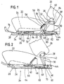
- Fig. 1 eine Seitenansicht eines Kraftfahrzeugsitzes (in schematischer Darstellung) mit in Normalposition befindlicher Rückenlehne und
- Fig. 2 eine Darstellung entsprechend Fig. 1, jedoch in gekippter Position der Rückenlehne.
- Fig. 1 is a side view of a motor vehicle seat (in a schematic representation) with the backrest in the normal position and
- Fig. 2 is a representation corresponding to FIG. 1, but in the tilted position of the backrest.
Der aus den Figuren ersichtliche Kraftfahrzeugsitz hat eine Rückenlehne 20, ein Sitzteil 22 und eine Längsführung 24. Letztere besteht aus jeweils einer Sitzschiene 26 und einer Bodenschiene 28 für beide Sitzseiten, in der Figur ist lediglich eine Sitzseite gezeigt und es genügt, die im folgenden zu beschreibende Verstellvorrichtung lediglich an einer Sitzseite vorzusehen. Dies soll nicht ausschließen, daß sie an beiden Sitzseiten angeordnet ist.The motor vehicle seat shown in the figures has a
Mit der Sitzschiene 26 ist einerseits der Sitzteil 22 verbunden, andererseits ist im hinteren Bereicht der Sitzschiene 26 die Rückenhlehne 20 gehalten, dies erfolgt über einen fest mit der Sitzschiene 26 verbundenen und in Richtung der Rückenlehne 20 aufragenden Tragarm 30 und ein zwischen diesem Tragarm 30 und der Rückenlehne 20 vorge sehenes, in den Figuren nicht dargestelltes, jedoch ansich bekanntes Rückenlehnengelenk. Dieses kann in bekannter Weise durch einen im oberen Bereich der Rückenlehne befindlichen Betätigungshebel schnellentriegelt werden, so daß unabhängig von der vorgesehenen Feinverstellung die Rückenlehne 20 frei bewegbar gekippt werden kann.On the one hand, the
Im gezeigten Ausführungsbeispiel ist die Rückenlehne 20 um eine im Tragarm 30 gelagerte Achse 32 schwenkbar. Um diese Achse 32 erfolgt auch die Feinverstellung mittels des Rückenlehnengelenks. Es ist aber auch möglich, an der Achse den unteren Arm eines ansich bekannten Gelenkbeschlages zu befestigen, dessen oberer Arm mit der Rückenlehne 20 selbst verbunden ist. Dann erfolgt die Feinverstellung um eine andere Schwenkachse als die Achse 32 und es ergibt sich der Vorteil, daß die Schwenkbewegungen für die Feineinstellung und die Kippbewegung völlig voneinander getrennt sind, so daß das der Feineinstellung dienende Rückenlehnengelenk arretiert bleiben kann, wenn die Rückenlehne gekippt werden soll. Es ist dann nicht notwendig, die Arretierposition des Rückenlehnengelenks zu speichern, um beim Zurückkippen der Rückenlehne 20 dieselbe Neigungsposition wieder zu erhalten.In the exemplary embodiment shown, the
Die Bodenschiene 28 ist normalerweise mit dem (nicht dargestellten) Kfz-Chassis verbunden, es ist aber auch möglich, daß zwischen ihr und dem Kfz-Chassis eine Vorrichtung zur Höhenverstellung angeordnet ist, beispielsweise eine Verstellvorrichtung mit Keil oder eine Verstellvorrichtung entsprechend der DE-OS 28 13 534. Mit dem Begriff "Sitzschiene" ist auch ein eventuell vorhandener Sitzträger umfaßt, der entweder mit einem Teilbe reich die Sitzschiene ausbildet oder separat ausgeführt und mit der Sitzschiene 26 verbunden ist.The
Die Rückenlehne 20 ist über die mit ihr verbundene Achse 32 drehfest mit einem Steuerhebel 34 verbunden, der vom unteren Bereich der Rückenlehne 20 in Richtung zur Sitzschiene 26 ragt und im oberen Bereich der Sitzschiene 26 einen Mitnehmer 36 aufweist. Der gezeigte Steuerhebel 34 ist im wesentlichen L-förmig, sein einer Schenkel ragt nach unten und trägt den als Bolzen ausgebildeten Mitnehmer 36, der andere Arm ragt nach hinten und trägt einen Anschlagzapfen 38. Sofern das Rückenlehnengelenk zwischen dem Steuerhebel 34 und der Achse 32 angeordnet ist, ist der Anschlagzapfen nicht mit der Rückenlehne 20 verbunden. Ist aber im Gegensatz zum gezeigten Ausführungsbeispiel und wie oben beschrieben die Achse 32 mit dem unteren Arm eines Gelenkbeschlags verbunden und befindet sich die Schwenkachse der Feinverstellung oberhalb der Achse 32, so kann der Anschlagzapfen mit dem unteren Arm des Gelenkbeschlages verbunden sein. Für den Anschlagzapfen 38 sind im Tragarm ein bogenförmiger Freibereich und zwei endseitige Anschläge 40, 42 vorgesehen, die die Kippbewegung der Rückenlehne 20 in beiden Schwenkrichtungen begrenzen.The
Im hinteren Bereich der Sitzschiene ist um eine Achse 44 schwenkbar ein Freigabehebel 46 angelenkt, der sich im wesentlichen in Längsrichtung der Sitzschiene 26 erstreckt und etwa dieselben Höhenabmessungen wie diese hat. Er bildet mit seinem Oberrand im linken, von der Achse 44 entfernten Bereich eine Löseflanke 48 aus, die schräg nach hinten und etwa im Winkel von 45° zur Sitzschiene 26 ansteigt und hat weiterhin eine diese fortsetzende Halte flanke 50, die in der in Figur 2 gezeigten Position des Freigabehebels 36 auf einem Kreisbogen um die Achse 32 liegt, wie er vom Mitnehmer 36 beschrieben wird. Die Löseflanke 48 hat dagegen einen größeren Abstand von der Achse 32 als die Halteflanke 50, sie verläuft zudem in einem Winkel zu ihrer Verbindung mit der Achse 32, der oberhalb des Winkels der Selbsthemmung liegt.In the rear area of the seat rail, a
In Richtung zur Sitzvorderkante hin hat der Freigabehebel 46 einen nach schräg vorn oben vorspringenden Hals 52, in dessen Endbereich der Mantel eines als Mitnehmereinheit dienenden Bowdenzuges 54 befestigt ist. Das zugehörige Seil 56 ist in einer Abwinklung des Tragarms 30 befestigt, Hals 52 und Abwinklung werden durch eine Feder 58 gegeneinander gezogen, wodurch der Freigabehebel 46 beständig gegen den Mitnehmer 36 vorbelastet ist und dadurch in Anlage am Mitnehmer 36 bleibt. Zudem wird eine Klapperfreiheit erzielt. Die Länge der Halteflanke 50 ist aus den Abstand der beiden Anschläge 40, 42 abgestimmt. Es ist auch möglich, die Anschläge 40, 42 am rechten Ende der Halteflanke 50 und links seitlich neben der Löseflanke 48 vorzusehen, sie wirken dann mit dem Mitnehmer 36 zusammen.In the direction of the front edge of the seat, the
Weiterhin ist an der Sitzschiene 26 ein Schlepphebel 60 angeordnet, der eine U-förmige, nach oben und zum Mitnehmer 36 hin offene Betätigungsbucht 62 hat, in die der Mitnehmer 36 ständig eingreift. Die Betätigungsbucht 62 ist aus Montagegründen nach oben offen, sie könnte auch abgeschlossen sein. Der Schlepphebel 60 ist über ein Schubgelenk an der Sitzschiene 26 und seiner Längsrichtung verschiebbar angeordnet, im konkreten Ausführungsbeispiel springt etwas links von der Längenmitte der Sitzschiene 26 ein mit dieser starr verbundener Bolzen 64 vor, der von einem im Schlepphebel 60 ausgeführten Langloch 66 umgriffen wird. Der freie Verschiebungsweg des Langloches 66 gegenüber dem Bolzen 64 und/oder eventuell ein vorgesehener Endanschlag der Längsführung 24 bestimmen den freien Verschiebungsweg der Sitzschiene 26 mit ihrem Sitzteil 22 und der Rückenlehne 20 gegenüber der Bodenschiene 28.Furthermore, a
Der Schlepphebel 60 hat einen gradlinig verlaufenden, unteren Rand, von dem jedoch schräg unterhalb der Betätigungsbucht 62 ein Merkzapfen 68 nach unten vorspringt. Dieser ist normalerweise, wie Figur 1 zeigt, außer Eingriff mit einer Rastenleiste 70 der Bodenschiene 28, er kann jedoch in ein Rastfenster der Rastenleiste 70 hineingedrückt werden, wie Figur 2 zeigt. Die geometrische Abstimmung ist dabei so getroffen, daß bei einer vollständigen Arretierung der in den Figuren nicht näher dargestellten Arretiervorrichtung 72 (gezeigt ist ein Handhebel 74 und ein Betätigungshebel 78) der Merkzapfen 68 stets in ein Fenster oder eine Bucht der Rastenleiste 70 eintaucht, wenn er nach unten gedrückt wird. Der Merkzapfen 68 kann entsprechend V-förmig oder anderweitig nach unter spitzer zulaufend ausgebildet sein, damit eine gewisse Fehlpositionierung aufgrund des notwendigen Spiels des Mitnehmers 36 in der Betätigungsbucht 62 selbsttätig ausgeglichen wird.The
Zur besseren Positionierung des Schlepphebels 60 ist zusätzlich noch ein zweites Schubgelenk vorgesehen, das im gezeigten Ausführungsbeispiel durch einen Bolzen 80 gebildet wird, der unterhalb der Betätigungsbucht 62 am Schlepphebel 60 vorspringt und mit einem Langloch 82 zusammenwirkt, das die gleiche effektive Länge wie das Langloch 66 hat. Es verläuft parallel zur geradlinigen Unterkante des Freigabehebels 46 und in geringem Abstand unterhalb der Halteflanke 50, die etwa die gleiche Gesamtlänge wie das Langloch 82 hat.For better positioning of the
Das andere Ende des Bowdenzuges 54 ist mantelseitig an der Sitzschiene 26 und seilseitig am Betätigungshebel 78 der Arretiervorrichtung 72 festgelegt. Vergrößert sich der Abstand zwischen dem Hals 52 und der Abwinklung des Tragarms 30, so wird der Betätigungshebel 78, wie ein Vergleich der Figuren 1 und 2 zeigt, angehoben, er hebt im Sinne einer Schleppeinrichtung den Handhebel 74 an, wodurch die Arretiervorrichtung 72 freigegeben wird. Andere Ausbildungen ohne mechanisches Anheben des Handhebels 74 sind möglich.The other end of the
Im folgenden wird die Funktion erläutert:
Figur 1 zeigt die Normalposition der Rückenlehne 20. Die beiden Hebel 46, 60 sind inaktiv, der Merkzapfen 68 befindet sich außer Eingriff mit der Rastenleiste 70, der Mitnehmer 36 befindet sich am unteren Ende der Löseflanke 48 und liegt am Hals 52 an. Dadurch steht die Unterkante des Freigabehebels 46 in einem sehr spitzen Winkel zur Längsführung 24. Die Arretiervorrichtung 72 ist arretiert.The function is explained below:
Figure 1 shows the normal position of the
Wird nun die Verriegelung der Rückenlehne 20 durch Betätigung eines entsprechenden, im oberen Bereich der Rükkenlehne 20 vorgesehenen (nicht dargestellten) Hebels freigegeben, so kann die Rückenlehne 20 um die Achse 32 verschwenkt werden. Innerhalb der ersten Winkelgrade einer Schwenkbewegung drückt der am unteren Ende der Löseflanke 48 anliegende und vorzugsweise als Rolle ausgebildete Mitnehmer 36 den Freigabehebel 46 und zugleich über den im Langloch 82 geführten Bolzen 80 den Schlepphebel 60 nach unten, wodurch der Merkzapfen 68 in Eingriff in ein freies Fenster der Rastenleiste 70 kommt. Dabei schwenken die beiden Hebel 46, 60 im Gegensinn zueinander, der Freigabehebel 46 schwenkt um die Achse 44, der Schlepphebel 60 um den Bolzen 64. Die Schwenkbewegung des Freigabehebels 46 führt dazu, daß ein Zug auf das Seil 56 des Bowdenzuges 54 ausgeübt wird, der jedoch erst dann zu einer Entriegelung der Arretiervorrichtung 72 führt, wenn zuvor der Merkzapfen 68 ausreichend tief in ein Fenster der Rastenleiste 70 eingegriffen hat.If the locking of the
Bei der Weiterführung der Schwenkbewegung der Rückenlehne 20 um ihre Achse 32 erreicht der Mitnehmer 36 das obere Ende der Löseflanke 48, wodurch die Arretiervorrichtung 72 freigegeben wird, diese Freigabe wird aufrecht erhalten, wenn der Mitnehmer 36 anschließend auf die Halteflanke 50 gelangt. In diesem Zustand verläuft der Freigabehebel 46 mit seiner Unterkante ungefähr parallel zur Längsführung 24, ebenfalls verläuft die geradlinige Oberkante des Schlepphebels 60 ungefähr bündig zur Oberkante der Sitzschiene 26. Die Rückenlehne 20 kann soweit nach vorn geklappt werden, bis der Anschlagzapfen 38 an den Anschlag 40 kommt, diese Position ist in Figur 2 gezeigt.When the pivoting movement of the
In der in Figur 2 gezeigten Position ist der Fahrzeugsitz nach vorn verschoben, so daß der Einstieg zu einem Fondsitz vereinfacht ist. Die Verschiebung der Längsführung 24 wird im gezeigten Ausführungsbeispiel dadurch begrenzt, daß der Anschlagzapfen 38 an den Anschlag 40 kommt, alternativ könnte auch der Bolzen 64 an das linke Ende des Langlochs 66 an schlagen, da der Schlepphebel 60 über den im Eingriff befindlichen Merkzapfen 68 mit der Bodenschiene 28 verbunden ist, wird eine weitere Verschiebung der Sitzschiene 26 nach vorn blockiert.In the position shown in Figure 2, the vehicle seat is shifted forward, so that the entry to a rear seat is simplified. The displacement of the
Beim Zurückkippen der Rückenlehne 20 laufen die beschiebenen Vorgänge umgekehrt ab. Zugleich mit dem Zurückkippen bewegt sich der Sitz innerhalb der Längsführung 24 nach hinten. Kurz vor Erreichen der Normalposition gemäß Fig. 1 rutscht zunächst der Mitnehmer 46 ausreichend tief die Löseflanke 48 herunter, so daß die Arretiervorrichtung 72 einrasten kann, bevor der Merkzapfen 68 außer Eingriff mit der Rastenleiste 70 kommt.When the
Wie insbesondere aus Figur 2 ersichtlich ist, verläuft die Löseflanke 48 dann, wenn sich der Mitnehmer 36 auf ihr befindet, klappsymmetrisch zu einer Lotrechten zur Längsführung 24 und durch die Achse 32. Dadurch kann der Freigabehebel 46 die aus den Figuren ersichtliche, geringe Bauhöhe erhalten, zugleich ist das Maß der Bewegung des Mitnehmers 36 innerhalb der Betätigungsbucht 62 gering, diese kann also auch eine geringe Höhe haben. In einer alternativen Ausbildung ist keine Betätigungsbucht 62 vorgesehen, vielmehr ist der Steuerhebel 34 am Mitnehmer 36 an den Schlepphebel 60 angelenkt. Dann aber hat der Merkzapfen 68 eine ausreichende Länge, um während der geringen Schwenkbewegung des Schlepphebels 60, wenn der Mitnehmer 36 die Halteflanke 50 entlangfährt, stets ausreichend tief in der Rastenleiste 70 zu bleiben.As can be seen in particular from FIG. 2, the
Bei dem bisher beschriebenen Kraftfahrzeugsitz ist die Kippbewegung der Rückenlehne 20 starr mit der Längsverschiebung des Sitzes in der Längsführung 24 gekoppelt. Dadurch können Probleme auftreten, wenn der Sitz ohnehin schon innerhalb der Längsführung 24 relativ weit nach vorn verschoben wurde, bevor seine Rückenlehne gekippt und er noch weiter nach vorn verschoben werden soll, denn die Rückenlehne 20 kann beispeilsweise an ein Lenkrad anschlagen und dadurch die weitere Bewegung nach vorn behindern, oder die Längsführung 24 schlägt an einen normalerweise vorgesehenen, eigenen Anschlag an, wodurch wiederum das Kippen der Rückenlehne 20 blockiert ist. Um diese Probleme zu beseitigen, ist das vorderste Fenster für den Merkzapfen 68 nach vorn frei, so daß die Rückenlehne 20 gekippt werden kann, ohne daß eine Längsverschiebung erfolgt. In einer anderen Ausführung ist der Steuerhebel 34 nicht drehstarr mit der Rückenlehne 20, sondern um die Achse 32 schwenkbar mit dieser verbunden, er wird durch eine Feder gegen einen Anschlag 84 gedrückt. Durch den Anschlag wird sichergestellt, daß die in Figur 1 gezeigte Position stets wieder eingenommen wird. Der Anschlag 84 ist mit der Rückenlehne 20 verbunden. Die Feder ist vorzugsweise so ausgeführt, daß sie während des Beginns einer Kippbewegung der Rückenlehne 20 zunächst steif ist, anschließend aber, wenn die Rückenlehne 20 in die stärkste Kipposition gelangt praktisch kraftlos ist und somit die Rückenlehne 20 nicht selbsttätig wieder aufgerichtet wird.In the motor vehicle seat described so far, the tilting movement of the
Claims (14)
- die durch eine Arretiervorrichtung (72) arretierbar ist und
- die aus einer Bodenschiene (28) und einer Sitzschiene (26) aufgebaut ist, von denen die Bodenschiene (28) mit dem Kraftfahrzeugchassis verbindbar ist und eine Rastenleiste (70) aufweist und die Sitzschiene (26) einerseits den Sitzteil (22) trägt und andererseits über einen Tragarm (30) und über ein ein- und feststellbares Rückenlehnengelenk mit der Rückenlehne (20) verbunden ist,
dadurch gekennzeichnet, daß die Rückenlehne (20) mit einem Steuerhebel (34) verbunden ist, der vom Rücklehnengelenk in Richtung zur Sitzschiene (26) vorspringt und einen Mitnehmer (36) aufweist, und daß an der Sitzschiene (26) einerseits ein Freigabehebel (46) angelenkt ist,
- der eine Löseflanke (48) und eine Halteflanke (50) aufweist, die jeweils mit dem Mitnehmer (36) zusammenwirken und
- der über eine Mitnehmereinheit mit der Arretiervorrichtung (78) verbunden ist
und andererseits ein Schlepphebel (60) angeordnet ist,
- der eine Betätigungsbucht (62) hat, in die der Mitnehmer (36) eingreift,
- der einen nach unten in Richtung der Rastenleiste (70) der Bodenschiene (28) vorspringenden und dieser zugeordneten Merkzapfen (68) aufweist und
- der über ein Schubgelenk (64, 66) mit der Sitzschiene (28) verbunden ist,
so daß in Normalposition der Rückenlehne (20) der Freigabehebel (46) und der Schlepphebel (60) inaktiv sind, in einer Zwischenposition der Rückenlehne (20) der Merkzapfen (68) in die Rastenleiste (70) eingegriffen hat, die Arretiervorrichtung (72) aber arretiert ist, und in einer vollständig gekippten Position der Rückenlehne (20) die Arretiervorrichtung (72) freigegeben und die Sitzschiene (26) mit Sitzteil (22) und Rückenlehne (20) innerhalb des durch das Schubgelenk (64, 66) bzw. eines Anschlags der Längsführung (24) definierten Weges gegenüber der Bodenschiene (28) frei verschiebbar ist.1. motor vehicle seat, which is longitudinally displaceable by tilting its backrest (20) and has a seat part (22) and a longitudinal guide (24),
- Which can be locked by a locking device (72) and
- Which is constructed from a bottom rail (28) and a seat rail (26), of which the bottom rail (28) can be connected to the motor vehicle chassis and has a notch bar (70) and the seat rail (26) on the one hand carries the seat part (22) and on the other hand is connected to the backrest (20) via a support arm (30) and via an adjustable and lockable backrest joint,
characterized in that the backrest (20) is connected to a control lever (34) which projects from the backrest joint in the direction of the seat rail (26) and has a driver (36), and in that on the one hand a release lever (46 ) is articulated,
- Which has a release flank (48) and a holding flank (50), each of which cooperate with the driver (36) and
- Which is connected via a driver unit with the locking device (78)
and on the other hand a rocker arm (60) is arranged,
- Which has an actuating bay (62), in which the driver (36) engages,
- Which has a downward projection in the direction of the catch bar (70) of the bottom rail (28) and associated with this pin (68) and
- which is connected to the seat rail (28) via a sliding joint (64, 66),
so that in the normal position of the backrest (20) the release lever (46) and the rocker arm (60) are inactive, in an intermediate position of the backrest (20) the notch (68) has engaged in the catch bar (70), the locking device (72) but is locked, and in a fully tilted position of the backrest (20) the locking device (72) is released and the seat rail (26) with the seat part (22) and backrest (20) within by the sliding joint (64, 66) or one Stop of the longitudinal guide (24) defined path relative to the floor rail (28) is freely displaceable.
Priority Applications (2)
| Application Number | Priority Date | Filing Date | Title |
|---|---|---|---|
| DE19863608827 DE3608827A1 (en) | 1986-03-17 | 1986-03-17 | Motor-vehicle seat which can be displaced longitudinally by tilting its backrest |
| EP19870104066 EP0286693B1 (en) | 1987-03-19 | 1987-03-19 | Motorcar seat which can be displaced longitudinally by tipping of his back |
Applications Claiming Priority (1)
| Application Number | Priority Date | Filing Date | Title |
|---|---|---|---|
| EP19870104066 EP0286693B1 (en) | 1987-03-19 | 1987-03-19 | Motorcar seat which can be displaced longitudinally by tipping of his back |
Publications (2)
| Publication Number | Publication Date |
|---|---|
| EP0286693A1 true EP0286693A1 (en) | 1988-10-19 |
| EP0286693B1 EP0286693B1 (en) | 1990-12-27 |
Family
ID=8196852
Family Applications (1)
| Application Number | Title | Priority Date | Filing Date |
|---|---|---|---|
| EP19870104066 Expired - Lifetime EP0286693B1 (en) | 1986-03-17 | 1987-03-19 | Motorcar seat which can be displaced longitudinally by tipping of his back |
Country Status (1)
| Country | Link |
|---|---|
| EP (1) | EP0286693B1 (en) |
Cited By (2)
| Publication number | Priority date | Publication date | Assignee | Title |
|---|---|---|---|---|
| DE4122770A1 (en) * | 1991-07-10 | 1993-01-14 | Heidelberger Druckmasch Ag | PLATE OF A BOW PRINTING MACHINE |
| FR2876636A1 (en) * | 2004-10-18 | 2006-04-21 | Peugeot Citroen Automobiles Sa | Seat e.g. middle seat, guiding mechanism for e.g. minivan, has elastic cable to actuate slide, to be fixed to seat, by tractive force towards rear position of seat, when slide is located between front and rear positions of seat |
Citations (9)
| Publication number | Priority date | Publication date | Assignee | Title |
|---|---|---|---|---|
| DE2233915A1 (en) * | 1971-07-10 | 1973-01-18 | Ikeda Bussan Co | SUPPORT CONSTRUCTION FOR A MOVABLE VEHICLE SEAT |
| DE2434409A1 (en) * | 1973-07-23 | 1975-02-20 | Nissan Motor | DEVICE FOR UNLOCKING A LENGTH ADJUSTABLE SEAT |
| DE2640425A1 (en) * | 1975-09-08 | 1977-04-21 | Cox Of Watford Ltd | ADJUSTMENT MECHANISM FOR A VEHICLE SEAT |
| DE2812322A1 (en) * | 1977-03-18 | 1978-09-21 | Gen Motors Corp | VEHICLE SEAT |
| DE2813534A1 (en) * | 1978-03-29 | 1979-10-04 | Bayerische Motoren Werke Ag | SEAT FOR MOTOR VEHICLES WITH A SEAT SECTION THAT CAN BE MOVED FORWARD BY A TILTABLE BACKREST |
| DE3151105A1 (en) * | 1980-12-26 | 1982-10-28 | Ikeda Bussan Co., Ltd., Yokohama, Kanagawa | ADJUSTABLE SEAT ARRANGEMENT FOR A MOTOR VEHICLE |
| DE3226198A1 (en) * | 1981-07-13 | 1983-02-03 | General Motors Corp., Detroit, Mich. | SEAT CONTROL MECHANISM FOR VEHICLE SEATS |
| EP0135596A1 (en) * | 1983-09-20 | 1985-04-03 | KEIPER RECARO GmbH & Co. | Motor vehicle seat, especially for two-door motor vehicles |
| EP0196773A2 (en) * | 1985-03-25 | 1986-10-08 | General Motors Corporation | Easy entry seat adjuster |
-
1987
- 1987-03-19 EP EP19870104066 patent/EP0286693B1/en not_active Expired - Lifetime
Patent Citations (9)
| Publication number | Priority date | Publication date | Assignee | Title |
|---|---|---|---|---|
| DE2233915A1 (en) * | 1971-07-10 | 1973-01-18 | Ikeda Bussan Co | SUPPORT CONSTRUCTION FOR A MOVABLE VEHICLE SEAT |
| DE2434409A1 (en) * | 1973-07-23 | 1975-02-20 | Nissan Motor | DEVICE FOR UNLOCKING A LENGTH ADJUSTABLE SEAT |
| DE2640425A1 (en) * | 1975-09-08 | 1977-04-21 | Cox Of Watford Ltd | ADJUSTMENT MECHANISM FOR A VEHICLE SEAT |
| DE2812322A1 (en) * | 1977-03-18 | 1978-09-21 | Gen Motors Corp | VEHICLE SEAT |
| DE2813534A1 (en) * | 1978-03-29 | 1979-10-04 | Bayerische Motoren Werke Ag | SEAT FOR MOTOR VEHICLES WITH A SEAT SECTION THAT CAN BE MOVED FORWARD BY A TILTABLE BACKREST |
| DE3151105A1 (en) * | 1980-12-26 | 1982-10-28 | Ikeda Bussan Co., Ltd., Yokohama, Kanagawa | ADJUSTABLE SEAT ARRANGEMENT FOR A MOTOR VEHICLE |
| DE3226198A1 (en) * | 1981-07-13 | 1983-02-03 | General Motors Corp., Detroit, Mich. | SEAT CONTROL MECHANISM FOR VEHICLE SEATS |
| EP0135596A1 (en) * | 1983-09-20 | 1985-04-03 | KEIPER RECARO GmbH & Co. | Motor vehicle seat, especially for two-door motor vehicles |
| EP0196773A2 (en) * | 1985-03-25 | 1986-10-08 | General Motors Corporation | Easy entry seat adjuster |
Cited By (2)
| Publication number | Priority date | Publication date | Assignee | Title |
|---|---|---|---|---|
| DE4122770A1 (en) * | 1991-07-10 | 1993-01-14 | Heidelberger Druckmasch Ag | PLATE OF A BOW PRINTING MACHINE |
| FR2876636A1 (en) * | 2004-10-18 | 2006-04-21 | Peugeot Citroen Automobiles Sa | Seat e.g. middle seat, guiding mechanism for e.g. minivan, has elastic cable to actuate slide, to be fixed to seat, by tractive force towards rear position of seat, when slide is located between front and rear positions of seat |
Also Published As
| Publication number | Publication date |
|---|---|
| EP0286693B1 (en) | 1990-12-27 |
Similar Documents
| Publication | Publication Date | Title |
|---|---|---|
| DE19921786B4 (en) | Slide rail for a vehicle seat with storage of the longitudinal adjustment and the seat, which includes such a slide rail | |
| EP1165342B1 (en) | Automobile seat | |
| EP0872375B1 (en) | Inclination-adjusting fitting with tilting device for backrests of automotive vehicle seats | |
| DE10151762B4 (en) | Predisplaceable motor vehicle seat with access to a rear seat through a front door | |
| EP2655125B1 (en) | Longitudinally adjustable vehicle seat | |
| EP1390226B1 (en) | Easy-entry vehicle seat whose seat back releases when returning to a memory position | |
| DE69926936T2 (en) | Slide rail for vehicle seat and seat equipped with such rail | |
| DE3151105C2 (en) | ||
| DE10344640B4 (en) | Seat latch assembly | |
| DE3608827A1 (en) | Motor-vehicle seat which can be displaced longitudinally by tilting its backrest | |
| DE19510618A1 (en) | Vehicle seat, which can be moved longitudinally if backrest is folded | |
| DE20314237U1 (en) | Memory device for a rail longitudinal guide of a motor vehicle | |
| WO2002040310A2 (en) | Motor vehicle seat | |
| EP0135596B1 (en) | Motor vehicle seat, especially for two-door motor vehicles | |
| EP2004448B1 (en) | Adjusting system for a vehicle seat | |
| DE4201829A1 (en) | Vehicle seat with folding backrest - has locking and release levers to permit forward movement of folded seat | |
| EP1337417B1 (en) | Motor vehicle seat | |
| DE10057724A1 (en) | Vehicle seat has actuator stop on component that pivots with backrest that acts on rotatable coupling element of coupling mechanism when backrest is tilted forwards | |
| WO2015028244A1 (en) | Fitting with a pivoting-forwards mechanism and an easy-entry latch, and vehicle seat with such a fitting | |
| EP1392545B1 (en) | Motor vehicle seat | |
| EP1395459B1 (en) | Motor vehicle seat | |
| DE102005031252B4 (en) | Backrest unit of a motor vehicle seat | |
| DE102017220226B4 (en) | RAIL-BASED ADJUSTMENT DEVICE IN A VEHICLE | |
| DE202009002580U1 (en) | Automotive seat | |
| DE102017220223A1 (en) | ADJUSTING RAIL IN VEHICLE |
Legal Events
| Date | Code | Title | Description |
|---|---|---|---|
| PUAI | Public reference made under article 153(3) epc to a published international application that has entered the european phase |
Free format text: ORIGINAL CODE: 0009012 |
|
| 17P | Request for examination filed |
Effective date: 19880407 |
|
| AK | Designated contracting states |
Kind code of ref document: A1 Designated state(s): FR GB |
|
| RBV | Designated contracting states (corrected) |
Designated state(s): FR |
|
| 17Q | First examination report despatched |
Effective date: 19900308 |
|
| GRAA | (expected) grant |
Free format text: ORIGINAL CODE: 0009210 |
|
| AK | Designated contracting states |
Kind code of ref document: B1 Designated state(s): FR |
|
| ET | Fr: translation filed | ||
| PLBE | No opposition filed within time limit |
Free format text: ORIGINAL CODE: 0009261 |
|
| STAA | Information on the status of an ep patent application or granted ep patent |
Free format text: STATUS: NO OPPOSITION FILED WITHIN TIME LIMIT |
|
| 26N | No opposition filed | ||
| PGFP | Annual fee paid to national office [announced via postgrant information from national office to epo] |
Ref country code: FR Payment date: 19940224 Year of fee payment: 8 |
|
| PG25 | Lapsed in a contracting state [announced via postgrant information from national office to epo] |
Ref country code: FR Free format text: LAPSE BECAUSE OF NON-PAYMENT OF DUE FEES Effective date: 19951130 |
|
| REG | Reference to a national code |
Ref country code: FR Ref legal event code: ST |