EP0286573A2 - No-return valve for dirty liquid or gaseous fluid - Google Patents
No-return valve for dirty liquid or gaseous fluid Download PDFInfo
- Publication number
- EP0286573A2 EP0286573A2 EP88710005A EP88710005A EP0286573A2 EP 0286573 A2 EP0286573 A2 EP 0286573A2 EP 88710005 A EP88710005 A EP 88710005A EP 88710005 A EP88710005 A EP 88710005A EP 0286573 A2 EP0286573 A2 EP 0286573A2
- Authority
- EP
- European Patent Office
- Prior art keywords
- sealing element
- partition
- openings
- check valve
- valve
- Prior art date
- Legal status (The legal status is an assumption and is not a legal conclusion. Google has not performed a legal analysis and makes no representation as to the accuracy of the status listed.)
- Withdrawn
Links
Images
Classifications
-
- F—MECHANICAL ENGINEERING; LIGHTING; HEATING; WEAPONS; BLASTING
- F16—ENGINEERING ELEMENTS AND UNITS; GENERAL MEASURES FOR PRODUCING AND MAINTAINING EFFECTIVE FUNCTIONING OF MACHINES OR INSTALLATIONS; THERMAL INSULATION IN GENERAL
- F16K—VALVES; TAPS; COCKS; ACTUATING-FLOATS; DEVICES FOR VENTING OR AERATING
- F16K15/00—Check valves
- F16K15/14—Check valves with flexible valve members
Definitions
- Check valves generally have the task of allowing the direction of flow of a medium in a pipe or the like in only one direction. This is intended, for example, to prevent the pumped medium from flowing back, for example in the event of a sudden drop in pressure in the pipeline, and from transporting undesired constituents in the wrong direction.
- the task of a check valve can be to supply liquid or gaseous additives to a medium in a container or in a pipeline through a further pipeline at higher pressure if required. It must be ensured that, for. B. in the event of an interruption in the supply, if the pressure in the metering line is lower than that in the container or in the mixing line, backflow of the medium supplied with the additives is prevented. This means that the container or the mixing line must be closed securely and quickly with respect to the metering line, the internal pressure generally supplying the energy required for the closing of the check valve.
- check valves can, for example, prevent toxic gas or liquids from escaping to the outside or into a pipeline system in the event of an unforeseen loss of pressure, and pose incalculable dangers to the environment. In other cases, it can be of considerable economic importance to prevent the backflow of contaminated media if this could destroy expensive devices and machines.
- the required tasks can be covered with sufficient certainty by commercially available check valves.
- a more or less elastic circular disk is normally pressed by the container or pipeline pressure against a smaller opening provided with a raised edge, whereby this is closed.
- the elasti cal disc can be made of rubber, for example. To prevent it from deforming due to the pressure acting and no longer closes securely, it is pressure-side with another disk made of rigid material, for. B. brass provided. This ensures that the sealing element rests at all points on the sealing edge without bending or bending.
- a valve disk designed in this way also requires a guide which ensures that it only moves normally to the closing plane and cannot be moved laterally. This is achieved, for example, in that the brass disk has a central pin which is movable in the longitudinal direction in a bore. A compression coil spring is also placed on the pin between the disc and the bore, which presses the valve disk against the valve seat. This ensures that the valve disc is securely positioned on the valve seat even when the tank or pipeline is depressurized.
- Valves of this type have the disadvantage, on the one hand, that production is relatively expensive. On the other hand, after some time, the sealing element tends to harden in the area of the annular sealing point, which leads to leaks. Too soft elements would have the disadvantage of yielding too much to the contact pressure, so that the required tightness would also not be guaranteed.
- the object of the present invention is now to avoid these disadvantages. This is achieved primarily by using a highly elastic sealing element which seals over a large area and also seals securely even when there are dirt particles between the sealing surface and the sealing element and is not damaged on the surface. Furthermore, the elasticity of the sealing material is sufficient to close the flow openings even in the unpressurized state, without additional external forces having to be applied, for example by a helical spring. This is achieved by deforming and prestressing the sealing element against the passage openings so that it seals due to its own elasticity.
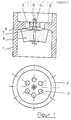
- a generally round valve body 1 has a partition 2 across the flow of the flowing medium, which with openings, for. B. holes 3 is provided.
- the partition 2 is level on one side and tapered on the other side towards the center.
- On this hollow side there is an elastic sealing element 4, for example made of rubber, the diameter of which is larger than the outermost limit of the openings.
- an elastic sealing element 4 for example made of rubber, the diameter of which is larger than the outermost limit of the openings.
- a screw 5 with which the sealing element is held in the center of the openings.
- the screw also has the task of compressing the sealing element 4 in the middle by means of a nut 6 and washer 7, so that a more or less inwardly lowered end face is produced.
- the screw 5 is fastened in the middle bore of the partition 2 with the nut 8 so that no more movement is possible, and the sealing element 4 is biased against the partition 2.
- valve from the side of the partition 2 If the valve from the side of the partition 2 is pressurized with a liquid or gaseous medium under a certain pressure, it can flow through the openings 3 in the partition 2, since the sealing element 4 yields on the outer edge due to its elastic property and Flow with relatively low resistance releases Prerequisite for this is that the pressure on the side of the sealing element 4 is lower than on the side of the partition 2. On the other hand, the sealing element is able to close the valve tightly in the opposite direction if there are opposite pressure conditions .
- the valve also closes tightly when dirt particles settle between the sealing element 4 and the partition 2, since the elastic material can deform sufficiently.
Abstract
Description
Rückschlagventile haben im allgemeinen die Aufgabe, die Fließrichtung eines Mediums in einem Rohr oder dergleichen in nur einer Richtung zu ermöglichen. Dadurch soll beispielsweise verhindert werden, daß das geförderte Medium etwa bei plötzlichem Druckabfall in der Rohrleitung zurückfließt und unerwünschte Bestandtteile in die falsche Richtung transportiert. Ebenso kann die Aufgabe eines Rückschlagventiles darin bestehen, einem Medium in einem Behälter oder in einer Rohrleitung bei Bedarf flüssige oder gasförmige Zusatzstoffe durch eine weitere Rohrleitung mit höherem Druck zuzuführen. Dabei muß sichergestellt werden, daß z. B. bei einer Unterbrechung der Zuführung, wenn der Druck in der Dosierleitung kleiner ist als der in dem Behälter oder in der Mischleitung, ein Rückfließen des mit den Zusatzstoffen versorgten Mediums verhindert wird. Das bedeutet, daß der Behälter bzw. die Mischleitung gegenüber der Dosierleitung sicher und schnell verschlossen werden muß, wobei in der Regel der innere Druck die notwendige Energie für die Schließung des Rückschlagventils liefert.Check valves generally have the task of allowing the direction of flow of a medium in a pipe or the like in only one direction. This is intended, for example, to prevent the pumped medium from flowing back, for example in the event of a sudden drop in pressure in the pipeline, and from transporting undesired constituents in the wrong direction. Likewise, the task of a check valve can be to supply liquid or gaseous additives to a medium in a container or in a pipeline through a further pipeline at higher pressure if required. It must be ensured that, for. B. in the event of an interruption in the supply, if the pressure in the metering line is lower than that in the container or in the mixing line, backflow of the medium supplied with the additives is prevented. This means that the container or the mixing line must be closed securely and quickly with respect to the metering line, the internal pressure generally supplying the energy required for the closing of the check valve.
Durch den Einbau von Rückschlagventilen kann beispielsweise verhindert werden, daß giftige Gas oder Flüssigkeiten bei unvorhergesehenem Druckverlust nach außen oder in ein Leitungssystem gelangen und unkalkulierbare Gefahren für die Umwelt darstellen. In anderen Fällen kann es von erheblicher wirtschaftlicher Bedeutung sein, den Rückfluß verschmutzter Medien zu verhindern, wenn dadurch unter Umständen kostspielige Geräte und Maschinen zerstört werden könnten.The installation of check valves can, for example, prevent toxic gas or liquids from escaping to the outside or into a pipeline system in the event of an unforeseen loss of pressure, and pose incalculable dangers to the environment. In other cases, it can be of considerable economic importance to prevent the backflow of contaminated media if this could destroy expensive devices and machines.
In der Regel können die geforderten Aufgaben von handelsüblichen Rückschlagventilen mit genügender Sicherheit abgedeckt werden. Dabei wird normalerweise eine mehr oder weniger elastische kreisförmige Scheibe durch den Behälter- oder Rohrleitungsdruck gegen eine kleinere mit erhöhtem Rand versehene Öffnung gepreßt, wobei diese verschlossen wird. Die elasti sche Scheibe kann beispielsweise aus Gummi bestehen. Um zu verhindern, daß sie sich infolge des einwirkenden Druckes verformt und nicht mehr sicher schließt, wird sie druckseitig mit einer weiteren Scheibe aus steifem Material, z. B. Messing, versehen. Dadurch wird gewährleistet, daß das Dichtelement ohne durch- oder aufzubiegen an allen Stellen des Dichtrandes anliegt.As a rule, the required tasks can be covered with sufficient certainty by commercially available check valves. A more or less elastic circular disk is normally pressed by the container or pipeline pressure against a smaller opening provided with a raised edge, whereby this is closed. The elasti cal disc can be made of rubber, for example. To prevent it from deforming due to the pressure acting and no longer closes securely, it is pressure-side with another disk made of rigid material, for. B. brass provided. This ensures that the sealing element rests at all points on the sealing edge without bending or bending.
Ein so gestalteter Ventilteller benötigt darüberhinaus eine Führung, die sicherstellt, daß er nur normal zur Schließebene bewegt und nicht seitlich verschoben werden kann. Dies wird beispielsweise dadurch verwirklicht, daß die Messingscheibe einen zentrischen Zapfen besitzt, der in einer Bohrung in Längsrichtung beweglich ist. Auf dem Zapfen zwischen Scheibe und Bohrung wird zusätzlich eine Druck-Schraubenfeder angeordnet, die den Ventilteller gegen den Ventilsitz drückt. So wird erreicht, daß der Ventilteller auch in drucklosem Behälter- oder Rohrleitungszustand sicher auf dem Ventilsitz positioniert wird.A valve disk designed in this way also requires a guide which ensures that it only moves normally to the closing plane and cannot be moved laterally. This is achieved, for example, in that the brass disk has a central pin which is movable in the longitudinal direction in a bore. A compression coil spring is also placed on the pin between the disc and the bore, which presses the valve disk against the valve seat. This ensures that the valve disc is securely positioned on the valve seat even when the tank or pipeline is depressurized.
Wird ein solches Rückschlagventil von der Seite der elastischen Scheibe her mit einem Druck und mit einer damit verbundenen Kraft beaufschlagt, die die entgegengesetzt wirkende aus Innendruck und Schraubenfeder resultierende Kraft übersteigt, so hebt der Ventilteller vom Ventilsitz ab und ein flüssiges oder gasförmiges Medium kann das Ventil in Richtung des geringeren Druckes passieren. Bei umgekehrten Kraftverhältnissen wird der Ventilteller gegen den Sitz gepreßt und die Öffnung verschlossen. Auf diese Weise wird gewährleistet, daß ein solches Rückschlagventil nur in einer Richtung durchflossen werden kann.If such a non-return valve is subjected to pressure and associated force from the side of the elastic disc, which exceeds the opposing force resulting from internal pressure and coil spring, the valve disc lifts off the valve seat and a liquid or gaseous medium can flow into the valve happen in the direction of the lower pressure. If the force is reversed, the valve disk is pressed against the seat and the opening is closed. In this way it is ensured that such a check valve can only flow through in one direction.
Derartige Ventile haben einerseits den Nachteil, daß die Herstellung relativ kostenaufwendig ist. Andererseits neigt das Dichtungselement nach einiger Zeit im Bereich der ringförmigen Dichtstelle zur Verhärtung, die zu Undichtheiten führt. Zu weiche Elemente hätten den Nachteil, dem Anpreßdruck zu sehr nachzugeben, so daß die geforderte Dichtheit ebenfalls nicht gewährleistet würde.Valves of this type have the disadvantage, on the one hand, that production is relatively expensive. On the other hand, after some time, the sealing element tends to harden in the area of the annular sealing point, which leads to leaks. Too soft elements would have the disadvantage of yielding too much to the contact pressure, so that the required tightness would also not be guaranteed.
Vor allem aber, wenn schmutzhaltige Medien den Ventilsitz passieren, kann es zu Problemen kommen. Verunreinigungen, beispielsweise Sandkörnchen, setzen sich zwischen Dichtrand und Dichtelement und werden unter Umständen in den bereits verhärteten Werkstoff gepreßt. Ebenso kann die Oberfläche des Dichtrandes durch scharfkantige und harte Schmutzteilchen beschädigt werden. In beiden Fällen ist nicht mehr gewährleistet, daß das Ventil absolut dicht schließt.But above all, if dirty media pass through the valve seat, problems can arise. Contaminants, such as grains of sand, settle between the sealing edge and the sealing element and may be pressed into the already hardened material. The surface of the sealing edge can also be damaged by sharp-edged and hard dirt particles. In both cases it is no longer guaranteed that the valve closes absolutely tightly.
Aufgabe der vorliegenden Erfindung ist es nun, diese Nachteile zu vermeiden. Dies wird in erster Linie dadurch erreicht, daß ein hochelastsiches Dichtelement verwendet wird, welches großflächig abdichtet und auch dann, wenn sich Schmutzteilchen zwischen Dichtfläche und Dichtelement befinden, noch sicher abdichtet und an der Oberfläche nicht beschädigt wird. Weiterhin reicht die Elastizität des Dichtwerkstoffes aus, die Durchflußöffnungen auch in drucklosem Zustand zu verschließen, ohne daß zusätzliche äußere Kräfte zum Beispiel durch eine Schraubenfeder aufgebracht werden müssen. Dies wird erreicht, indem das Dichtelement verformt und vorgespannt gegen die Durchlaßöffnungen gepreßt wird, so daß es auf Grund der eigenen Elastizität abdichtet.The object of the present invention is now to avoid these disadvantages. This is achieved primarily by using a highly elastic sealing element which seals over a large area and also seals securely even when there are dirt particles between the sealing surface and the sealing element and is not damaged on the surface. Furthermore, the elasticity of the sealing material is sufficient to close the flow openings even in the unpressurized state, without additional external forces having to be applied, for example by a helical spring. This is achieved by deforming and prestressing the sealing element against the passage openings so that it seals due to its own elasticity.
Die erfindungsgemäße Ausführung eines solchen Rückschlagventils ist in Figur 1 im Schnitt und in der Draufsicht dargestellt und wird an Hand dieses Bildes nachstehend erläutert:The design of such a check valve according to the invention is shown in section and in plan view in FIG. 1 and is explained below using this picture:
Ein in der Regel runder Ventilkörper 1 besitzt quer zur Strömung des durchfließenden Mediums eine Trennwand 2, die mit Durchbrüchen, z. B. Bohrungen 3, versehen ist. Die Trennwand 2 ist auf der einen Seite planeben und auf der anderen Seite zur Mitte hin kegelig abfallend bearbeitet. Auf dieser hohlen Seite befindet sich ein elastisches Dichtelement 4, beispielsweise aus Gummi, deren Durchmesser größer ist als die äußerste Begrenzung der Durchbrüche. In der Mitte des Dichtelementes 4 sitzt eine Schraube 5, mit der das Dichtelement im Zentrum der Durchbrüche gehalten wird. Die Schraube hat weiterhin die Aufgabe, das Dichtlelement 4 in der Mitte mittels Mutter 6 und Unterlegscheibe 7 zusammenzudrücken, so daß eine mehr oder weniger nach innen abgesenkte Stirnfläche entsteht.A generally
Die Schraube 5 wird in der mittleren Bohrung der Trennwand 2 mit der Mutter 8 so befestigt, daß keine Bewegung mehr möglich ist, und das Dichtelement 4 vorgespannt gegen die Trennwand 2 gedrückt wird.The
Durch die Verformung der Stirnfläche des Dichtelementes 4 wird in Verbindung mit der kegeligen Hohle der Trennwand 2 zwischen diesen beiden im Bereich der Durchbrüche ein Hohlraum geschaffen, und die Dichtwirkung auf eine kreisringförmige Fläche außerhalb der Durchbrüche verlagert.The deformation of the end face of the
Wird das Ventil von der Seite der Trennwand 2 her mit einem flüssigen oder gasförmigen Medium unter einem bestimmten Druck beaufschlagt, so kann diese durch die Durchbrüche 3 in der Trennwand 2 hindurchströmen, da das Dichtelement 4 auf Grund ihrer elastischen Eigenschaft am äußeren Rand nachgibt und den Durchfluß mit relativ geringem Widerstand freigibt Vorraussetzung dafür ist, daß der Druck auf der Seite des Dichtelementes 4 geringer ist als auf der Seite der Trennwand 2. Andererseits ist das Dichtlelement in der Lage, das Ventil in umgekehrter Richtung dicht zu verschließen, wenn entgegengesetzte Druckverhältnisse herrschen.If the valve from the side of the
Das Ventil schließt auch dann dicht, wenn sich Schmutzpartikel zwischen Dichtelement 4 und Trennwand 2 setzen, da sich das elastische Material ausreichend verformen kann.The valve also closes tightly when dirt particles settle between the
Ea hat sich gezeigt, daß das entwickelte Rückschlagventil die gestellten Anforderungen voll erfüllt und vor allem in Hinblick auf Störanfälligkeit sicher arbeitet. Ein Aufbiegen des Dichtelementes 4 am äußeren Rand wird auch in drucklosem Zustand sicher verhindert, da es unter Vorspannung im Ventilkörper befestigt ist.Ea has shown that the check valve developed fully meets the requirements and works safely, especially with regard to susceptibility to faults. Bending of the sealing
Claims (5)
Applications Claiming Priority (2)
| Application Number | Priority Date | Filing Date | Title |
|---|---|---|---|
| DE8705153U | 1987-04-07 | ||
| DE8705153U DE8705153U1 (en) | 1987-04-07 | 1987-04-07 |
Publications (2)
| Publication Number | Publication Date |
|---|---|
| EP0286573A2 true EP0286573A2 (en) | 1988-10-12 |
| EP0286573A3 EP0286573A3 (en) | 1989-03-29 |
Family
ID=6806798
Family Applications (1)
| Application Number | Title | Priority Date | Filing Date |
|---|---|---|---|
| EP88710005A Withdrawn EP0286573A3 (en) | 1987-04-07 | 1988-04-07 | No-return valve for dirty liquid or gaseous fluid |
Country Status (2)
| Country | Link |
|---|---|
| EP (1) | EP0286573A3 (en) |
| DE (1) | DE8705153U1 (en) |
Cited By (1)
| Publication number | Priority date | Publication date | Assignee | Title |
|---|---|---|---|---|
| EP0531234A1 (en) * | 1991-09-05 | 1993-03-10 | KIS PHOTO INDUSTRIE S.a.r.l. | Device for automatic compensation of evaporation in chemical treatment tanks |
Families Citing this family (2)
| Publication number | Priority date | Publication date | Assignee | Title |
|---|---|---|---|---|
| DE19955886A1 (en) * | 1999-11-20 | 2001-05-23 | Bosch Gmbh Robert | Solenoid valve with a check valve |
| CN103775687B (en) * | 2014-01-28 | 2016-10-26 | 南通市红星空压机配件制造有限公司 | A kind of pressure check valve structure |
Citations (3)
| Publication number | Priority date | Publication date | Assignee | Title |
|---|---|---|---|---|
| FR1537110A (en) * | 1967-07-11 | 1968-08-23 | Improvement in valves of hydraulic devices, in particular shock absorbers and other suspension components | |
| DE6602486U (en) * | 1967-07-21 | 1969-06-12 | Loctite Technik Gmbh & Co Kg | CUFF VALVE |
| FR2291428A1 (en) * | 1974-11-15 | 1976-06-11 | Chaudronnerie Indle Et Agricol | Industrial type non return valve - has flexible membrane mounted in cylindrical housing and co-operating with perforated outlet channel |
-
1987
- 1987-04-07 DE DE8705153U patent/DE8705153U1/de not_active Expired
-
1988
- 1988-04-07 EP EP88710005A patent/EP0286573A3/en not_active Withdrawn
Patent Citations (3)
| Publication number | Priority date | Publication date | Assignee | Title |
|---|---|---|---|---|
| FR1537110A (en) * | 1967-07-11 | 1968-08-23 | Improvement in valves of hydraulic devices, in particular shock absorbers and other suspension components | |
| DE6602486U (en) * | 1967-07-21 | 1969-06-12 | Loctite Technik Gmbh & Co Kg | CUFF VALVE |
| FR2291428A1 (en) * | 1974-11-15 | 1976-06-11 | Chaudronnerie Indle Et Agricol | Industrial type non return valve - has flexible membrane mounted in cylindrical housing and co-operating with perforated outlet channel |
Cited By (1)
| Publication number | Priority date | Publication date | Assignee | Title |
|---|---|---|---|---|
| EP0531234A1 (en) * | 1991-09-05 | 1993-03-10 | KIS PHOTO INDUSTRIE S.a.r.l. | Device for automatic compensation of evaporation in chemical treatment tanks |
Also Published As
| Publication number | Publication date |
|---|---|
| DE8705153U1 (en) | 1987-06-04 |
| EP0286573A3 (en) | 1989-03-29 |
Similar Documents
| Publication | Publication Date | Title |
|---|---|---|
| EP0271765B1 (en) | Self fluid controlled valve releasable by an especially solenoid controlled pilot valve | |
| DE2149406C3 (en) | Backflow prevention valve | |
| DE602004007356T2 (en) | VALVE AND METHOD FOR PROVIDING A FLUID IMPULSE | |
| DE2042327A1 (en) | Diaphragm valve | |
| DE2623301B2 (en) | Double seat valve with leak control | |
| EP2527700A1 (en) | Valve | |
| WO1983000907A1 (en) | Valve for fluids | |
| DE4001731A1 (en) | PRESSURE VESSEL | |
| EP0286573A2 (en) | No-return valve for dirty liquid or gaseous fluid | |
| DE4321787C2 (en) | Ball check valve | |
| DE60117387T2 (en) | FLOW CONTROL VALVE | |
| DE102016205772B4 (en) | Quick opening valve for a pressurized extinguishing fluid container and extinguishing fluid container with selbigem | |
| DE3333518A1 (en) | THREE-WAY BALL VALVE | |
| DE3003480C2 (en) | ||
| DE1550468A1 (en) | Pressure control valve | |
| EP1855014B1 (en) | FIlling valve | |
| AT326438B (en) | VALVE SEAL | |
| EP1413812A2 (en) | Diaphragm valve with fan-shaped diaphragm support | |
| DE102019133996A1 (en) | Valve | |
| DE1550468C3 (en) | Double seat valve | |
| DE102020130440A1 (en) | Overpressure protection to limit the pressure of a fluid | |
| DE202022106308U1 (en) | check valve | |
| DE102020124511A1 (en) | Flow limiter for a fuel injection system and fuel injection system with a flow limiter | |
| DE3010905A1 (en) | CHECK VALVE | |
| DE928335C (en) | Gate valve |
Legal Events
| Date | Code | Title | Description |
|---|---|---|---|
| PUAI | Public reference made under article 153(3) epc to a published international application that has entered the european phase |
Free format text: ORIGINAL CODE: 0009012 |
|
| AK | Designated contracting states |
Kind code of ref document: A2 Designated state(s): AT BE CH DE ES FR GB GR IT LI LU NL SE |
|
| PUAL | Search report despatched |
Free format text: ORIGINAL CODE: 0009013 |
|
| AK | Designated contracting states |
Kind code of ref document: A3 Designated state(s): AT BE CH DE ES FR GB GR IT LI LU NL SE |
|
| STAA | Information on the status of an ep patent application or granted ep patent |
Free format text: STATUS: THE APPLICATION IS DEEMED TO BE WITHDRAWN |
|
| 18D | Application deemed to be withdrawn |
Effective date: 19890930 |