EP0286544A2 - Echtzeitfestkörperspeicher mit Reservebatterie - Google Patents
Echtzeitfestkörperspeicher mit Reservebatterie Download PDFInfo
- Publication number
- EP0286544A2 EP0286544A2 EP88400861A EP88400861A EP0286544A2 EP 0286544 A2 EP0286544 A2 EP 0286544A2 EP 88400861 A EP88400861 A EP 88400861A EP 88400861 A EP88400861 A EP 88400861A EP 0286544 A2 EP0286544 A2 EP 0286544A2
- Authority
- EP
- European Patent Office
- Prior art keywords
- real time
- power
- line
- time clock
- elapsed
- Prior art date
- Legal status (The legal status is an assumption and is not a legal conclusion. Google has not performed a legal analysis and makes no representation as to the accuracy of the status listed.)
- Withdrawn
Links
Images


Classifications
-
- G—PHYSICS
- G01—MEASURING; TESTING
- G01R—MEASURING ELECTRIC VARIABLES; MEASURING MAGNETIC VARIABLES
- G01R11/00—Electromechanical arrangements for measuring time integral of electric power or current, e.g. of consumption
- G01R11/02—Constructional details
- G01R11/25—Arrangements for indicating or signalling faults
-
- G—PHYSICS
- G01—MEASURING; TESTING
- G01R—MEASURING ELECTRIC VARIABLES; MEASURING MAGNETIC VARIABLES
- G01R11/00—Electromechanical arrangements for measuring time integral of electric power or current, e.g. of consumption
- G01R11/56—Special tariff meters
-
- G—PHYSICS
- G01—MEASURING; TESTING
- G01R—MEASURING ELECTRIC VARIABLES; MEASURING MAGNETIC VARIABLES
- G01R21/00—Arrangements for measuring electric power or power factor
- G01R21/133—Arrangements for measuring electric power or power factor by using digital technique
Definitions
- This invention relates generally to solid state time-of-use electricity meter registers for storing electrical energy consumption and corresponding real time data for customer billing, and more particularly, to a solid-state time-of-use electricity meter register having a battery backup energized circuit for preserving real time data while minimizing backup battery current consumption during a line power outrage.
- Electricity meter registers monitor line voltage and current as a function of time at each customer site to obtain electrical energy consumption billing data. This generally is carried out by electromechanical watt hour meters that use a disc which rotates as a function of electrical energy consumption and contain registers that display the electrical energy accumulated during a predetermined period of time, e.g., within one billing month. The meters must be read and reset at the end of each month.
- More sophisticated electrical energy consumption registers measure both kilowatt hour consumption and kilowatt demand at different billing rates depending upon the "real time” of consumption.
- "Real time” as used herein refers to time measured in terms of day of week and hours, minutes and seconds of the day.
- Customer billing rates are determined by the energy supplier in accordance with predetermined time or demand intervals. For example, electrical energy consumption measured during predetermined intervals of peak demand for energy are billed at a highest billing rate, and energy consumption at other predetermined time intervals of the day are billed at correspondingly lower billing rates. This method of metering is known as “time-of-day” or “time-of-use” metering and is commonly carried out in the industry to unify energy consumption throughout the day.
- a microprocessor-based control interrogates the output of the rotating electromechanical disc or line voltage and current measurement sensors to develop line power which is correlated with predetermined real time-of-use intervals to obtain customer billing data.
- An important requirement of such equipment is to retain the accumulated electrical energy consumption and real time data during a power outage, so that upon resumption of line power, no customer billing data or time data are lost. In this regard, time must continue to be measured during the power outage; otherwise, upon resumption of power, energy consumption will not be properly correlated with time-of-use intervals to develop accurate customer billing data.
- An example of a solid-state time-of-use electricity meter register has a microprocessor based circuit for interrogating line voltage and current measurement sensors to obtain electrical energy consumption data, and a real time clock in the microprocessor correlates the electrical energy consumption data with predetermined time-of-use intervals, to develop customer billing data.
- the circuit is powered by a main DC power supply connected to the power lines.
- the line power and real time data accumulated by the internal real time clock are written into an external random access memory that is powered by a backup battery.
- An external counter increments in response to pulses generated at a repetition rate of one pulse per eight seconds during the interval of the line power outage.
- the electrical energy consumption and real time data previously stored in the external memory are transferred back to the microprocessor.
- the count stored in the external counter is transferred to the microprocessor wherein the count is multiplied by the period of the counter (eight seconds), and the result is applied to update the real time read from the external memory. Updating of the real time of the microprocessor by the count stored in the counter is initiated upon the first eight second increment following resumption of line power.
- the pulse counting technique used in the Johnston et al patent presents a severe limitation to the maintenance of accurate customer billing data during a power outage, because updating of the real time maintained by the internal clock occurs up to eight seconds after the resumption of line power. Accordingly, among a large number of such meter registers within a region affected by a power outage, there is, on the average, a four second delay following resumption of power before the internal real time clock of each register is updated. Until the internal real time clock is updated, the energy consumed by each customer cannot be billed because there is no association between the energy consumed during the up to eight second delay and its corresponding real time-of-use billing interval.
- one object of this invention is to provide a method of and system for retaining electrical power and real time data within a time-of-use meter register during power outages.
- Another more particular object is to minimize loss of power and time-of-use data during power outages, by updating time-of-use data immediately following power resumption.
- a further object is to provide a method of and system for providing a battery backup for a solid-state electricity meter register wherein stored time-of-use data are updated by the elapsed time of the outage immediately upon resumption of line power.
- Another object of the invention is to provide a battery back-up system in a solid-state time-of-use electricity meter wherein battery current drain is minimized.
- a further object is to provide a fail-safe system in the battery back-up circuit of a solid state time-of-use electricity meter register wherein the electrical energy consumption and time-of-use data stored at the time of the power outage are not lost in an event of a back-up battery failure.
- Another object is to prevent loss of electrical energy consumption data in a solid-state time-of-use electricity meter register upon a power outage and back-up battery failure.
- An electricity meter register of a type to which the invention is directed comprises power line voltage and current measurement transducers and a processor means having an internal real time clock means for accumulating real time and means for processing line voltage and current measurements to obtain electrical energy consumption data during predetermined customer billing time intervals.
- the processor means which is energized by voltage on the power line, contains an internal memory means for storing the electrical energy consumption data and contains means for correlating the stored data to various customer billing rates corresponding to different rate-time intervals during the day established by the electrical energy supplier.
- a back-up circuit of the register comprises a non-volatile, external memory means, an external, real time clock means for accumulating elapsed real time from the beginning of a power outage and line power detector means for detecting line power outages and resumptions.
- the microprocessor Upon a power outage detected by the detector means, the microprocessor transfers the internal real time clock and power line data stored in the first memory means to the non-volatile, external memory means, and resets the external real time clock means to accumulate real time elapsed from the time of the beginning of the outage. The backup battery is then connected to the external real time clock means under control of the output of the main AC line derived power supply.
- the microprocessor reads the real time clock and power line data stored in the external memory means as well as the elapsed real time accumulated by the external real time clock means.
- the real time read from the external memory means which corresponds to the time at which the power outage occurred, is updated by the elapsed real time accumulated by the external real time clock means, and normal operation of the electricity meter continues.
- the back-up battery is disconnected from the external real time clock means prior to real time updating to minimize battery current drain.
- the detecting means for detecting power line outages and resumptions preferably monitors voltage on the power lines and, in response to a predetermined line voltage corresponding to an early stage of a line power failure, first transfers its stored data to the external memory means, then inhibits the microprocessor from transferring any further data to the external memory. This prevents the external memory from receiving any erratic data as the microprocessor powers down.
- the state of the back-up battery is periodically monitored to determine whether it has at least a predetermined current supply capacity. If not, the internal real time clock is not updated when line power resumes after a power outage. Electrical energy consumption data thereafter are stored in a totalizing register in the microprocessor, independent of any elapsed time-of-use data, and an alarm indicating that the internal real time clock has not been updated is displayed.
- a time-of-use electricity meter register in accordance with the invention is encased within a housing 12 having a plastic cover 14 having clear portions arranged to expose a solid-state display 16. Electromechanical display registers 18 and a name plate 20 are also provided adjacent solid state display 16.
- a meter register 10 is located by the electric energy supplier at each customer site to establish the amount of electric energy consumption for customer billing.
- the register 10 accumulates, among other data, time-of-use data as shown in Figure 3 wherein electricity usage is correlated with real time in day of year, hours, minutes, seconds format.
- the usage data consists of both energy readings and demand.
- the energy and peak power consumed by the customer is established by obtaining a sum of the quantities used in each time-of-use period.
- the utility uses the electricity consumption data obtained during an interval multiplied by the billing rate for that interval to arrive at a cost of the energy consumed by the customer.
- the meter register 10 accordingly must include a real time clock system for maintaining current time of day, and the clock system must remain operative during as long a period of time as possible. Even during power line outages, the real time clock must continue to operate; otherwise, electricity consumption by the customer and corresponding billing rates intervals will be out of phase with each other, and customer billing will be inaccurate.
- This invention is directed toward a method of and system for maintaining current real time in meter register 10 during line power outages so that upon resumption of line power, the real time clock system is immediately updated to account for the time elapsed during the outage, and no billing information is lost.
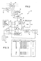
- circuitry 22 for operating the meter register 10 comprises a microprocessor 24 whose operation is synchronized by a crystal controlled oscillator 25.
- Microprocessor 24 includes an internal real time clock 26 whose time keeping is synchronized in a well-known fashion to the power line frequency (e.g. 60 Hz) via a power line clock interface (not shown).
- Microprocessor 24 also includes a read only memory (ROM) 28 for storing programming to control the microprocessor and its peripheral devices and a random access memory (RAM) 30 for storing energy consumption and demand data, real time data developed by the internal clock 26, and other data.
- the microprocessor supplies output signals to a display driver 32 that in turn drives display 16 to present alphanumeric characters at the face of the meter register 10, as shown in Figure 1.
- circuitry 22 is a conventional electromagnetic meter movement 34 having a current section 36 and a voltage section 38 connected in a conventional manner to the movement 34 for driving a shaft supported rotating disc 40 at a rotational rate corresponding to the consumption of electricity flowing in power line conductors P at the customer site.
- the rate of rotation of disc 40 is converted to a digital signal by an optical detector 42 in the meter movement 34, to be supplied to microprocessor 24 as electrical energy consumption data.
- the shaft of disc 40 is further mechanically coupled to the multidial meter register 18, shown in Figure 1.
- the internal clock 26 maintains real time, to be correlated with energy consumption as time-of-use data so that the proper billing rates corresponding to predetermined billing intervals can be applied to customer billing. As discussed previously, it is important to maintain measurement of real time for prolonged periods, e.g., years, even during intervals of power outage. To this end, provided herein in accordance with the invention is novel circuitry that cooperates with microprocessor 24 to preserve real time measurement during power outages in the meter register 10.
- the circuitry comprises an external random access memory (RAM) 44, an external real time clock 46, a back-up battery 48, power line outage detector 50 which includes a power-up reset feature, and a low battery detector 54.
- RAM random access memory
- real time refers to time measured in terms of day of the week and time-of-day, i.e., hours, minutes, seconds. Electricity for powering all components during normal operation of circuit 22 is obtained from a main DC power supply 15 connected to the power lines P.
- non-volatile type memory formed from conventional NMOS or CMOS circuitry.
- non-volatile refers to the property of retaining data in a non-energized state of the memory, that is, with no source of supply voltage applied to the RAM 44.
- the clock is reset by microprocessor 24 to accumulate real time elapsed from the beginning of the power outage and the battery 48 is then caused to be connected to external real time clock 46.
- the current capacity of the battery 48 which preferably is a lithium battery having a ten year shelf life and over 360 days of battery carryover, is less than a predetermined capacity, the battery remains connected to the clock 46, but no real time elapsed during the power outage will be accumulated.
- RAM 44 stores the electrical energy consumption and associated real time data that existed at the beginning of the power outage.
- the battery When there is a resumption of power, detected by detector 50, the battery is disconnected from the external clock, energy consumption and real time data stored in the RAM 44 are read by the microprocessor 24, and the elapsed real time accumulated by clock 46 is read by the microprocessor.
- the real time read from RAM 44 is updated by the elapsed real time read from clock 46, to obtain an updated real time, and the result is stored in the RAM 30.
- the real time now retained by the microprocessor 24 and incremented by the internal clock 26 is the current real time for correlating with energy consumption data to obtain customer billing.
- FIG. 7 having a first column labelled “time-of-use” and a second column labelled “real time clock 46".
- Each row of Figure 7 includes a day-of-use entry (e.g., 238 in the first entry) which corresponds to a day of the year (in this example, the 238th day with respect to a reference date, such as January 1) and a time-of-day entry (e.g., 12:00:00 in the first entry corresponds to noon).
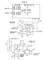
- Circuitry for carrying out the function of the line power outage detector 50 comprises first and second threshold detectors 50a, 50b connected to a stable reference source 57 such as a zener diode connected to the main DC supply 15.
- Each detector 50a, 50b is composed of a differential amplifier 54 having an non-inverting input connected to an unregulated output (+V) of power supply 15 through a resistance voltage divider consisting of resistors 58, 59 and an inverting input connected to the stable reference source 57.
- a pull-up resistor 61 and a feedback resistor 62 are connected in circuit with the differential amplifier 54 in a conventional manner.
- a capacitor 64 bypasses to ground any spurious signals at the output of power supply 15.
- Detectors 50a and 50b are identical to each other, except that the divider ratios of resistors 58, 59 of the two detectors are unequal and the values of the hysteresis resistors 62 of the two detectors are also unequal. This is to cause the "threshold" of detector 50a to be higher than that of detector 50b, for a reason that shall become clear from the discussion that follows. Assume that the magnitude of output voltage of the power supply 15 is nominally 5.0 volts. Resistors 58 and 59 of both detectors 50a, 50b have relative values such that in the absence of a power outage on power lines P, the magnitude of the voltage at node 60 of each detector is greater than that of the stable reference source 57.
- each differential amplifier 54 in detector 50a, 50b is at a "high" level, as shown by traces (a) and (b) of Figure 6.
- node 60 voltage decays correspondingly, as shown in trace (a) of Figures 6, until the node voltage intersects with the voltage V B of stable reference source 57 at point p.
- the output state of the differential amplifier 54 of detector 50a switches to a ground level, as shown by trace (b).
- the output of detector 50a is applied to an interrupt input I1 of the microprocessor 24, and in response, the microprocessor 24 executes a power down routine 60, shown in Figure 4.
- Step 62 of the power down routine 60 detects that a power outage has occurred and a power down sequence is to be carried out.
- step 64 electric energy and real time data stored in RAM 30 are transferred to the non-volatile RAM 44.
- the condition of back-up battery 48 is periodically monitored (e.g. once a day). Monitoring the condition of the backup battery 48 is carried out by a low battery detector 54, shown in Figure 2.
- the detector 54 shown in more detail in Figure 9, comprises a differential amplifier 80 having its inverting input connected to a 2.5 volt reference source (e.g. zener diode 57 mentioned above) derived from power supply 15, and its non-inverting input connected, through a resistor 82, to the battery 48.
- a resistor 83 is connected between resistor 82 and ground to ensure proper operation of comparator 80 if battery 48 is not present.
- a resistor 84 and diode 86 are connected between the non-inverting input and the output of differential amplifier 80, and a pull-up resistor 88 is connected between the output of the differential amplifier and the supply voltage +V.
- the output of the differential amplifier 80 is connected to an input port I2 of the microprocessor 24.
- step 80 When the battery voltage V B is greater than that supplied by the reference source 57, e.g. 2.5 volts, the magnitude of the voltage at the non-inverting input exceeds that of the inverting input, and the output of the differential amplifier 80 is at a "high" level. In response, microprocessor 24 determines that the current supplying capability of battery 48 is sufficient. On the other hand, if the magnitude of the battery voltage is less than 2.5 volts, the output of the differential amplifier 80 is a "ground” level, and microprocessor 24 determines that the battery 48 has failed, discharged or is not present. In response, a software flag is set (see step 98 of Fig. 5) to be used subsequently to energize an alarm display on display 16. The program now jumps to step 80.
- accumulated energy and demand data are first transferred from microprocessor 24 to RAM 44 (step 64) and the clock 46 is next zeroed by the microprocessor 24 on line 53 (step 76) to accumulate elapsed real time from the beginning of the outage.
- Zeroing and data storage takes place between the time of the first onset of power outage and the point when the supply voltage to microprocessor drops below a predetermined level (e.g. from 5.0 volts to 4.5 volts or less).
- the output of threshold detector 50b switches from a "high" state to the ground level as shown in trace (b) of Figure 6.
- the program waits for the ground (reset) level (steps 80, 82) at the output of detector 50b, and in response, disables the microprocessor (step 84).
- the battery 48 is then connected to clock 46 (step 86) via a switch 48a, shown in Figure 9, comprising a transistor switch 87 having its emitter and collector terminals connected between the backup battery 48 and real time clock 46.
- the base of the transistor 87 is connected through a resistor 89 to a source 15 of the main supply voltage +V, and a diode 91 is connected between the supply source and collector of the transistor.
- the reset disables the microprocessor as the microprocessor passes through an uncertainty region during power down where proper operation of the microprocessor cannot be guaranteed.
- the program recirculates to the main program at step 83 or to step 80 depending upon the output state of the detector 50a (step 88).
- the register 10 is now operating between times t12 and t2 in trace (c) of Figure 6.
- Step 92 of the power up sequence disconnects battery 48 from clock 46 (step 93). This is done by means of switch 48a which disconnects battery 48 from real time clock 46 as transistor 87 turns off in response to resumption of main supply voltage +V.
- Detector 50b applies a reset pulse on line 55 to the microprocessor and display reset terminals upon application to the reset circuit of power (step 94) to reset the microprocessor and blank display 16.
- step 96 the electrical energy consumption and real time data previously stored in RAM 44 are transferred back to internal RAM 30.
- step 98 The software flag is now read, in step 98, and if the flag was previously set in step 72 (step 100), an alarm is displayed by display 16 (step 103) to indicate that the real time clock of the register has not been updated. If on the other hand the low battery flag is not set, execution of the program continues to step 102 wherein the real time accumulated by clock 46 is transferred to the accumulator register (not shown) in microprocessor 24, and the real time data stored in RAM 30 is incremented by the elapsed real time (step 104). Time-of-use monitoring of the meter register continues in a normal manner (step 108).
- the battery backup switch 48a in the embodiment disclosed is a passive switch that responds to the relative magnitudes of the supply and battery voltages, the switch may alternatively be controlled by microprocessor 24.
Landscapes
- Physics & Mathematics (AREA)
- General Physics & Mathematics (AREA)
- Engineering & Computer Science (AREA)
- Power Engineering (AREA)
- Power Sources (AREA)
- Measurement Of Current Or Voltage (AREA)
- Electric Clocks (AREA)
Applications Claiming Priority (2)
| Application Number | Priority Date | Filing Date | Title |
|---|---|---|---|
| US3663387A | 1987-04-10 | 1987-04-10 | |
| US36633 | 1987-04-10 |
Publications (2)
| Publication Number | Publication Date |
|---|---|
| EP0286544A2 true EP0286544A2 (de) | 1988-10-12 |
| EP0286544A3 EP0286544A3 (de) | 1989-07-19 |
Family
ID=21889724
Family Applications (1)
| Application Number | Title | Priority Date | Filing Date |
|---|---|---|---|
| EP88400861A Withdrawn EP0286544A3 (de) | 1987-04-10 | 1988-04-11 | Echtzeitfestkörperspeicher mit Reservebatterie |
Country Status (4)
| Country | Link |
|---|---|
| EP (1) | EP0286544A3 (de) |
| BR (1) | BR8801658A (de) |
| CA (1) | CA1293995C (de) |
| MX (1) | MX169461B (de) |
Cited By (7)
| Publication number | Priority date | Publication date | Assignee | Title |
|---|---|---|---|---|
| EP0420535A2 (de) * | 1989-09-25 | 1991-04-03 | General Electric Company | Stromversorgung und Monitor zur Überwachung einer elektrischen Last nach einem Stromausfall |
| ES2088764A2 (es) * | 1994-03-14 | 1996-09-01 | Slace S A | Unidad local individual de telemedida y control de contadores electromecanicos aplicados a la medida de la electricidad. |
| EP0703654A3 (de) * | 1994-09-22 | 1996-12-04 | Spanner Pollux Gmbh | Elektronischer Verbrauchszähler mit Versorgungsschaltung |
| ES2107934A1 (es) * | 1994-07-28 | 1997-12-01 | Blanco Benito Roman Guerrero | Medidor de energia electrica activa con tarificador programable por el usuario. |
| US6219655B1 (en) * | 1997-09-17 | 2001-04-17 | Itron, Cin. | Method of RF-based communication |
| CN113625047A (zh) * | 2021-08-17 | 2021-11-09 | 北京京仪北方仪器仪表有限公司 | 一种具有冻结功能的智能电能表系统 |
| CN115484219A (zh) * | 2022-08-23 | 2022-12-16 | 中国电子科技集团公司第十研究所 | 规避国产srio交换芯片端口关联的方法、设备及介质 |
Citations (4)
| Publication number | Priority date | Publication date | Assignee | Title |
|---|---|---|---|---|
| GB2017937A (en) * | 1978-03-31 | 1979-10-10 | Westinghouse Electric Corp | Auxiliary power supply and timer arrangement for time registering multifunctional electric energy meters |
| GB2069153A (en) * | 1980-02-06 | 1981-08-19 | Sangamo Weston | Multitariff electricity meters |
| US4466074A (en) * | 1981-09-18 | 1984-08-14 | Mcgraw-Edison Company | Power outage timer |
| GB2136613A (en) * | 1980-02-05 | 1984-09-19 | Sangamo Weston | Data recorder with non-volatile solid state memory |
-
1988
- 1988-04-07 BR BR8801658A patent/BR8801658A/pt not_active IP Right Cessation
- 1988-04-08 MX MX011049A patent/MX169461B/es unknown
- 1988-04-08 CA CA000563600A patent/CA1293995C/en not_active Expired - Lifetime
- 1988-04-11 EP EP88400861A patent/EP0286544A3/de not_active Withdrawn
Patent Citations (4)
| Publication number | Priority date | Publication date | Assignee | Title |
|---|---|---|---|---|
| GB2017937A (en) * | 1978-03-31 | 1979-10-10 | Westinghouse Electric Corp | Auxiliary power supply and timer arrangement for time registering multifunctional electric energy meters |
| GB2136613A (en) * | 1980-02-05 | 1984-09-19 | Sangamo Weston | Data recorder with non-volatile solid state memory |
| GB2069153A (en) * | 1980-02-06 | 1981-08-19 | Sangamo Weston | Multitariff electricity meters |
| US4466074A (en) * | 1981-09-18 | 1984-08-14 | Mcgraw-Edison Company | Power outage timer |
Cited By (9)
| Publication number | Priority date | Publication date | Assignee | Title |
|---|---|---|---|---|
| EP0420535A2 (de) * | 1989-09-25 | 1991-04-03 | General Electric Company | Stromversorgung und Monitor zur Überwachung einer elektrischen Last nach einem Stromausfall |
| EP0420535A3 (en) * | 1989-09-25 | 1991-09-25 | General Electric Company | Power supply and monitor for controlling an electrical load following a power outage |
| ES2088764A2 (es) * | 1994-03-14 | 1996-09-01 | Slace S A | Unidad local individual de telemedida y control de contadores electromecanicos aplicados a la medida de la electricidad. |
| ES2107934A1 (es) * | 1994-07-28 | 1997-12-01 | Blanco Benito Roman Guerrero | Medidor de energia electrica activa con tarificador programable por el usuario. |
| EP0703654A3 (de) * | 1994-09-22 | 1996-12-04 | Spanner Pollux Gmbh | Elektronischer Verbrauchszähler mit Versorgungsschaltung |
| US6219655B1 (en) * | 1997-09-17 | 2001-04-17 | Itron, Cin. | Method of RF-based communication |
| CN113625047A (zh) * | 2021-08-17 | 2021-11-09 | 北京京仪北方仪器仪表有限公司 | 一种具有冻结功能的智能电能表系统 |
| CN115484219A (zh) * | 2022-08-23 | 2022-12-16 | 中国电子科技集团公司第十研究所 | 规避国产srio交换芯片端口关联的方法、设备及介质 |
| CN115484219B (zh) * | 2022-08-23 | 2023-06-27 | 中国电子科技集团公司第十研究所 | 规避国产srio交换芯片端口关联的方法、设备及介质 |
Also Published As
| Publication number | Publication date |
|---|---|
| MX169461B (es) | 1993-07-06 |
| CA1293995C (en) | 1992-01-07 |
| BR8801658A (pt) | 1988-11-16 |
| EP0286544A3 (de) | 1989-07-19 |
Similar Documents
| Publication | Publication Date | Title |
|---|---|---|
| US5216357A (en) | Real time solid state register having battery backup | |
| US4197582A (en) | Auxiliary power supply and timer arrangement for time registering multifunctional electric energy meters | |
| US4697182A (en) | Method of and system for accumulating verifiable energy demand data from remote electricity meters | |
| US4682169A (en) | Method of and system for accumulating verifiable energy demand data from remote electricity meters | |
| RU2126974C1 (ru) | Способ электронного измерения электроэнергии и устройство для его реализации (варианты) | |
| US4465970A (en) | Method and apparatus for multiple rate metering of electrical energy | |
| US4467434A (en) | Solid state watt-hour meter | |
| US6115676A (en) | Methods and apparatus for performing load profile and load control | |
| EP0052635B1 (de) | Elektrizitätszähler | |
| US6633825B2 (en) | Automatic calibration of time keeping for utility meters | |
| US4792677A (en) | System for use with a utility meter for recording time of energy use | |
| US4987363A (en) | Electric energy meter with power outage recovery circuit | |
| JPS62150499A (ja) | 電力需要デ−タ収集方法と装置 | |
| US4697180A (en) | System for accumulating verifiable energy demand data from remote electricity meters | |
| US4852030A (en) | Time-of-use-meter with a calendar of cyclic events | |
| EP0985152A1 (de) | Verbrauchsmessgeratät | |
| US5825648A (en) | Backup system for a time of day clock in an electronic device | |
| EP0286544A2 (de) | Echtzeitfestkörperspeicher mit Reservebatterie | |
| CA1237776A (en) | Time-of-use watt-hour meter with demand profile capability | |
| EP0248137B1 (de) | System zum Akkumulieren prüfbarer Energieverbrauchsdaten von fernen Elektrizitätsmessern | |
| US4348730A (en) | System for metering electrical energy with remote time signal correlation | |
| US4216527A (en) | System for metering electrical energy with remote time signal correlation | |
| KR100421298B1 (ko) | 전기 에너지 계량기의 발진기 보상 방법 | |
| US4697181A (en) | System for accumulating verifiable energy demand data from remote electricity meters | |
| JP2000074960A (ja) | 時間帯別電力量の計量方法および計量装置 |
Legal Events
| Date | Code | Title | Description |
|---|---|---|---|
| PUAI | Public reference made under article 153(3) epc to a published international application that has entered the european phase |
Free format text: ORIGINAL CODE: 0009012 |
|
| AK | Designated contracting states |
Kind code of ref document: A2 Designated state(s): AT BE DE ES FR GB IT LU NL |
|
| PUAL | Search report despatched |
Free format text: ORIGINAL CODE: 0009013 |
|
| AK | Designated contracting states |
Kind code of ref document: A3 Designated state(s): AT BE DE ES FR GB IT LU NL |
|
| RHK1 | Main classification (correction) |
Ipc: G01R 21/133 |
|
| 17P | Request for examination filed |
Effective date: 19900115 |
|
| 17Q | First examination report despatched |
Effective date: 19920114 |
|
| RAP1 | Party data changed (applicant data changed or rights of an application transferred) |
Owner name: SCHLUMBERGER INDUSTRIES, INC. |
|
| STAA | Information on the status of an ep patent application or granted ep patent |
Free format text: STATUS: THE APPLICATION IS DEEMED TO BE WITHDRAWN |
|
| 18D | Application deemed to be withdrawn |
Effective date: 19931026 |