EP0286360A2 - Self-supporting electrode with integral gas feed conduit - Google Patents
Self-supporting electrode with integral gas feed conduit Download PDFInfo
- Publication number
- EP0286360A2 EP0286360A2 EP88303028A EP88303028A EP0286360A2 EP 0286360 A2 EP0286360 A2 EP 0286360A2 EP 88303028 A EP88303028 A EP 88303028A EP 88303028 A EP88303028 A EP 88303028A EP 0286360 A2 EP0286360 A2 EP 0286360A2
- Authority
- EP
- European Patent Office
- Prior art keywords
- electrode
- wall
- air
- conduit
- fuel
- Prior art date
- Legal status (The legal status is an assumption and is not a legal conclusion. Google has not performed a legal analysis and makes no representation as to the accuracy of the status listed.)
- Granted
Links
Images

Classifications
-
- H—ELECTRICITY
- H01—ELECTRIC ELEMENTS
- H01M—PROCESSES OR MEANS, e.g. BATTERIES, FOR THE DIRECT CONVERSION OF CHEMICAL ENERGY INTO ELECTRICAL ENERGY
- H01M4/00—Electrodes
- H01M4/86—Inert electrodes with catalytic activity, e.g. for fuel cells
- H01M4/8605—Porous electrodes
- H01M4/8626—Porous electrodes characterised by the form
-
- H—ELECTRICITY
- H01—ELECTRIC ELEMENTS
- H01M—PROCESSES OR MEANS, e.g. BATTERIES, FOR THE DIRECT CONVERSION OF CHEMICAL ENERGY INTO ELECTRICAL ENERGY
- H01M8/00—Fuel cells; Manufacture thereof
- H01M8/10—Fuel cells with solid electrolytes
- H01M8/12—Fuel cells with solid electrolytes operating at high temperature, e.g. with stabilised ZrO2 electrolyte
- H01M8/1231—Fuel cells with solid electrolytes operating at high temperature, e.g. with stabilised ZrO2 electrolyte with both reactants being gaseous or vaporised
-
- H—ELECTRICITY
- H01—ELECTRIC ELEMENTS
- H01M—PROCESSES OR MEANS, e.g. BATTERIES, FOR THE DIRECT CONVERSION OF CHEMICAL ENERGY INTO ELECTRICAL ENERGY
- H01M8/00—Fuel cells; Manufacture thereof
- H01M8/24—Grouping of fuel cells, e.g. stacking of fuel cells
- H01M8/241—Grouping of fuel cells, e.g. stacking of fuel cells with solid or matrix-supported electrolytes
- H01M8/2425—High-temperature cells with solid electrolytes
- H01M8/243—Grouping of unit cells of tubular or cylindrical configuration
-
- H—ELECTRICITY
- H01—ELECTRIC ELEMENTS
- H01M—PROCESSES OR MEANS, e.g. BATTERIES, FOR THE DIRECT CONVERSION OF CHEMICAL ENERGY INTO ELECTRICAL ENERGY
- H01M8/00—Fuel cells; Manufacture thereof
- H01M8/10—Fuel cells with solid electrolytes
- H01M8/12—Fuel cells with solid electrolytes operating at high temperature, e.g. with stabilised ZrO2 electrolyte
- H01M2008/1293—Fuel cells with solid oxide electrolytes
-
- H—ELECTRICITY
- H01—ELECTRIC ELEMENTS
- H01M—PROCESSES OR MEANS, e.g. BATTERIES, FOR THE DIRECT CONVERSION OF CHEMICAL ENERGY INTO ELECTRICAL ENERGY
- H01M2300/00—Electrolytes
- H01M2300/0017—Non-aqueous electrolytes
- H01M2300/0065—Solid electrolytes
- H01M2300/0068—Solid electrolytes inorganic
- H01M2300/0071—Oxides
- H01M2300/0074—Ion conductive at high temperature
-
- Y—GENERAL TAGGING OF NEW TECHNOLOGICAL DEVELOPMENTS; GENERAL TAGGING OF CROSS-SECTIONAL TECHNOLOGIES SPANNING OVER SEVERAL SECTIONS OF THE IPC; TECHNICAL SUBJECTS COVERED BY FORMER USPC CROSS-REFERENCE ART COLLECTIONS [XRACs] AND DIGESTS
- Y02—TECHNOLOGIES OR APPLICATIONS FOR MITIGATION OR ADAPTATION AGAINST CLIMATE CHANGE
- Y02E—REDUCTION OF GREENHOUSE GAS [GHG] EMISSIONS, RELATED TO ENERGY GENERATION, TRANSMISSION OR DISTRIBUTION
- Y02E60/00—Enabling technologies; Technologies with a potential or indirect contribution to GHG emissions mitigation
- Y02E60/30—Hydrogen technology
- Y02E60/50—Fuel cells
Definitions
- This invention relates to self-supporting electrodes with integral gas feed conduits.
- Each fuel cell is formed on a long, electronically insulating, porous support tube, generally made of calcia stabilized zirconia, which provides structural integrity for the fuel cell.
- a thin, porous air electrode Surrounding, and deposited on this support tube, is a thin, porous air electrode, generivelyally from 20 microns to 200 microns, thick, deposited by well known techniques.
- the air electrode can be comprised of doped or undoped oxides or mixtures of oxides in the pervoskite family, such as LaMnO3, CaMnO3, LaNiO3, LaCoO3, LaCrO3, and the like.
- Generally surrounding the outer periphery of the air electrode is a gas tight, solid electrolyte, usually of yttria stabilized zirconia.
- Substantially surrounding the solid electrolyte is an outer, porous, fuel electrode, usually of nickel-zirconia cermet. Both the solid electrolyte and outer electrode are discontinuous to allow inclusion of an electrical interconnection material for series connection between cells.
- a separate, single, open end, thin, oxidant injector tube is used in the interior of each fuel cell, to flow gaseous oxidant into the cell. The oxidant contacts the support and diffuses through it to the air electrode.
- U.S. Patent Specification No. 4,596,750 (Ruka et al.), provided a fluorite type support tube material which would be better able to resist cracking due to migration of lanthanum or manganese materials contained in the contacting air electrode, at fuel cell operating temperatures of 1000°C.
- U.S. Patent Specification No. 4,598,028 (Rossing et al.), provided lighter weight, thinner, higher strength support tubes, which utilized a ceramic powder and ceramic fiber combination, allowing reduction of the oxygen path length to the air electrode through the support. Improvements have also been made to the air electrode, for example, U.S. Patent Specification No. 4,562,124 (Ruka), taught introduction of small amounts of cerium into the air electrode material, to provide a better match of coefficient of thermal expansion with the support tube.
- the invention resides in an elongated electrode, characterized in that said electrode comprisivelyes an electronically conductive self-supporting structure having an inner and outer wall and having an open end and a closed end, where the inner wall defines a conduit through the length of the electrode structure, where the area between the walls contains at least one additional conduit through the length of the electrode structure, and where the conduits communicate with each other near the closed end of the structure.
- the invention also resides in a plurality of such electrodes electronically connected together.
- the present invention provides a self-supporting, axially elongated, unitary electrode structure having an open end and a closed end, and having at least two conduits through its length connected near the closed end.
- a plurality of conduits are near its outer side wall with at least one additional conduit disposed inwardly from the conduits near the side wall.
- the electrode has an inner and outer wall, where the inner wall defines a conduit, preferably a central gas feed conduit parallel to the structure's longitudinal axis, through the length of the electrode structure, and where the area between the walls contains at least one other conduit, preferably a gas exit conduit through the length of the electrode structure.
- the end of the elongated electrode structure will be hollow, and capped or otherwise closed by a variety of designs.
- the conduits will communicate, i.e., connect with each other near the closed end, so that gas entering by way of the gas feed conduit will reverse direction and flow through the exit conduit in a direction countercurrent to the feed gas.
- a single gas feed conduit portion of an air electrode will be centrally located and will feed oxidant, there will be at least four gas exit conduits, and the electrode structure will be more dense near the central gas feed conduit than near the outer wall, so that gas will flow rather than diffuse to the gas exit conduits from the gas feed conduits.
- the central gas feed conduit can be longer than the rest of the electrode structure, extending outward along the axial length of the electrode, so that exiting, depleted oxidant gas can be used to react with depleted fuel near the extended feed conduit to heat incoming gas.
- openings can be machined in the outer wall past the active length of the cell, with the openings connecting to the gas exit conduits, to allow depleted gas to flow out of the openings after being used to heat incoming gas, and to combine with depleted fuel.
- the gas exit conduits are spaced near the outer side wall rather than in the center so that they can contact depleted fuel in the generator to preheat incoming air.
- Electrolyte and fuel electrode layers can be deposited over the air electrode to form annular cells, which can be electrically connected in series and also in parallel to similar adjacent cells.
- annular is used to describe a variety of layered cross-sections, for example, circular or square cross-sections.
- the fuel cell configuration provides a one piece high bulk electrode that incorporates a feed gas tube into the structure, and permits ease of electron travel, helping to eliminate circumferential current flow and circumferential voltage gradients.
- the elimination of the separate support tube reduces overall cell costs, eliminates one deposition step in manufacturing, and eliminates thermal mismatch and material migration problems. Elimination of the oxidant injector tubes makes for simple, strong, inexpensive, problem free generator design.
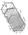
- a fuel cell generator 10 including a gas-tight housing 12.
- the housing 12 surrounds a plurality of chambers, including a generating chamber 14 and a combustion product or preheating chamber 16.
- An oxidant inlet chamber 18 can also be contained within the housing 12.
- the housing 12 is preferably comprised of steel, and lined throughout with a thermal insulation 22, shown as a thin layer for the sake of simplicity, such as low density alumina insulation.
- Penetrating the housing 12 and insulation 22 is a fuel inlet port 24, shown best in Figure 2, an air inlet port 26, and a combustion product outlet port 28, as well as ports for electrical leads.
- the generating chamber 14 extends between an end wall 30 of the housing 12 and a porous barrier 32, such as fibrous alumina felt.
- the preheating chamber 16 extends between the porous barrier 32 and a support structure for the gas inlet tube portion 20 of the fuel cells 40, such as a tube sheet 34.
- the oxidant inlet chamber 18 extends between the tube sheet 34 and another end wall 36 of the housing 12.
- the dividing barriers can include other structural types, and additional support and flow baffles can be incorporated.
- the shown barriers, the porous barrier 32 and the tube sheet 34 need not be sealed structures.
- the porous barrier 32 is designed to allow flow between the generating chamber 14, operating at an approximate pressure slightly above atmospheric, and the preheating chamber 16, operating at a slightly lower pressure. Gas flow is indicated by arrows 38 and 63. While the generator 10 is shown in a horizontal orientation in Figure 1, it can be operated in a vertical or other position.
- High temperature, elongated, solid oxide electrolyte, annular electrochemical cells, such as fuel cells 40 extend between the preheating chamber 16 and the generating chamber 14.
- the cells in one design, have completely open ends 42 in the preheating chamber 16, and closed end 44 in the generating chamber 14.
- the fuel cells are preferably tubular, including a solid oxide electrolyte sandwiched between two electrodes.
- Each cell includes an electrochemically active length 46 and an inactive length 48. The active length is contained within the generating chamber 14.
- Each individual cell generates approximately one volt, and a plurality are electronically interconnected, preferably in a series-parallel rectangular array.
- the arrangement can be described as including rows 50 and columns 52.
- Each cell in a row 50 is electronically connected along its active length 46 to the next adjacent cell, preferably through an interconnection felt 54 contacting their outer peripheries.
- an oxidant such as air
- the anode is the outer periphery of each cell and the cathode is on the inside.
- cell-to-cell contact within a row is in parallel, among adjacent anodes.
- Each cell in a column 52 is electronically interconnected in series to the next adjacent cell 40.
- this interconnection is made from the inner cathode of one cell to the outer anode of the next consecutive cell, through an interconnection felt 54.
- cells in the first row 50 ⁇ operate, for example, at approximately one volt, in the second row 50 ⁇ at approximately two volts, in the third row 50′′′ at approximately three volts, and so forth. Hundreds of cells can be so connected to achieve the desired voltage and current output.
- the direct current electrical energy thus generated is collected by a single current collector, preferably a conductive metal plate 56 or felt pad, positioned in electronic contact with each cell 40 in the first row 50 ⁇ , and a similar second collector (not shown), positioned in contact with the last row. Electrical leads 58, shown in Figure 2, are accordingly provided to the current collectors.
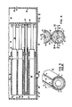
- a supported, prior art fuel cell 40 ⁇ having a thick support tube 2, which provides structural integrity to the cell, is shown.
- the support tube was typically comprised of calcia stabilized zirconia, forming a wall porous to gas permeation, approximately 1 mm to 2 mm thick.
- Surrounding the outer periphery of the support tube 2 was a thin porous air electrode or cathode 3.
- the cathode 3 was typically a composite oxide structure from 20 microns to 200 microns thick which was deposited onto the support tube through well-known techniques such as plasma spraying, or spraying or dipping in a slurry followed by sintering.
- Electrolyte 4, fuel electrode 7, interconnect 6 and nickel or cobalt layer 8 are also shown.
- a gas injector tube not shown in this Figure, was disposed in the open portion of the support tube.
- the prior art support tube is eliminated in the fuel cell design of this invention, one embodiment of which is shown in Figure 4, which utilizes a high bulk air electrode or cathode 3 ⁇ , having a central, integral gas feed conduit 41 which extends through the length of the air electrode.
- This air electrode may be made from doped or undoped oxide or mixture of oxides including but not limited to LaMnO3, CaMnO3, LaNiO3, LaCoO3 and LaCrO3.
- a preferred air electrode material is LaMnO3 doped with Sr.
- a gas-tight solid electrolyte 4 typically yttria stabilized zirconia, from 1 micron to 100 microns thick.
- a selected longitudinal segment 5, shown best in Figure 3, along the electrode axial length, is masked during deposition of the electrolyte, to provide a discontinuity, into which, an electronically conductive interconnect material 6 ⁇ is deposited.
- the interconnect material 6 ⁇ must be electronically conductive in both an oxygen and fuel environment.
- the interconnect is from 5 microns to 100 microns thick and is typically made of lanthanum chromite doped with calcium, strontium, or magnesium.
- a fuel electrode 7 ⁇ Surrounding the remainder of the cell except for the interconnect area is a fuel electrode 7 ⁇ which functions as the anode.
- a typical anode is 30 microns to 200 microns thick and is typically a nickel zirconia or cobalt zirconia cermet.
- a material 8 ⁇ , which is composed of porous nickel or cobalt metal is also deposited over the interconnect 6 ⁇ . This material is typically from 30 microns to 200 microns thick.
- a gaseous fuel such as hydrogen or carbon monoxide
- a source of oxygen passes through the inside of the cell to contact the air electrodes.
- the oxygen source forms oxygen ions at the electrode-electrolyte interface, which ions migrate through the electrolyte material to the anode, while electrons are collected at the cathode, thus generating a flow of electrical current in an external load circuit.
- a number of cells can be connected in series by electronic contact between the interconnect of one cell and the fuel electrode anode of another cell.
- one of the self-supporting, axially elongated, unitary designs of the electronically conducting air electrode 3 ⁇ of this invention is shown, with an integral, central gas feed conduit 41 and four surrounding gas exit conduits 43 disposed near the outer side walls of the electrode, and without the thick, tubular support 2, shown in the prior art Figure 3.
- the area 45 around the central oxidant feed conduit 41 is preferably more dense than the rest of the air electrode structure 3 ⁇ , so that oxidant gas will flow to the end of the cell, as shown in the cut away portion of Figure 2, rather than diffuse through the air electrode structure from conduit 41 to gas exit conduits 43.
- Density near conduit 41 can range from 75% to 90% while density near the outer wall can range from 20% to 50%. This density gradient can be accomplished during molding or extruding the air electrode, by using a finer particle size of the electrode material in the portion near the gas feed conduit, or by slip casting prior to or after sintering of the electrode.
- the particles used near the gas conduit will range from 0.1 micron to 10 microns, while the rest of the electrode will be made from particles ranging from 10 microns to 100 microns.
- Other possible air electrode designs are shown in Figures 5 and 6, all of which designs should be considered illustrative, and not in any way limiting. In these cases the plurality of conduits 43 are shown near the outer side wall 50, with at least one additional conduit 41, defined by inner wall 47, where conduit 41 is disposed inwardly from conduits 43 near the sidewall.
- the feed conduit 41 will be central to the air electrode cross section, and at least four, most preferably six to eight, exit conduits, as shown in Figures 4 and 6, will surround the cental feed conduit.
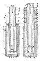
- Figure 7 shows an enlargement of the cross-section air electrode design, along line VII-VII of Figure 4.
- the closed end 44 of the cell is a simple end plug 65
- the air electrode is machined or otherwise cut in the green state at the entrance end where gas 63 flows in, to provide an extending air feed inlet conduit tube 20.
- the portion of the electrode structure containing the inner wall, i.e., tube 20, extends outwardly beyond the active length 46 of the cell.
- Dotted lines show the cut away portions 67 at: the entrance end . Cut away portions at the plug end are shown as the hollow portion 67′.
- the air enters the integral feed conduit tube 20, flowing down the gas feed conduit 41 until it reaches the closed end at plug 65, where it flows through the passage shown, and then reverse flows countercurrent to the inlet direction through gas exit conduits 43, and into combustion product chamber 16, when the cell is placed in a generator.
- the depleted oxidant contacts depleted fuel, and both combust to heat incoming oxidant 63.
- the gas exit conduits 43 are placed near the outer wall, rather than in the center of the electrode, so that this contact with depleted fuel and combustion to preheat incoming air is possible.
- Figure 7 can be modified, as shown in Figure 8, where a pre-formed end plug 65 is used.
- An advantage of this design is that the plug 65 cannot be pushed in so far as to cut off incoming oxidant gas, as is possible with the design of Figure 7.
- the air electrode can be made shorter than in Figure 7, and a separate, very dense inlet tube 20 can be cemented to the electrode, 3 ⁇ at joint 68.
- Figure 9 shows an end plug design somewhat similar to that of Figure 7, except that the hollow portion 67 ⁇ is made by machining the walls near the end of the oxidant feed conduit, such as at 69.
- holes or other openings are made by machining the walls near the entrance end of the electrode structure where the oxidant 63 enters. This would still allow flow of depleted oxidant into combustion product chamber 16. All of these embodiments are to be considered illustrative and not limiting, and show means disposed near the closed end of the electrode structure to allow reverse flow of oxidant feed gas.
- the self-supporting air electrode of the invention can be extruded, or it can be molded in a suitable die. After it is formed, and while in the green stage, all of the various heretofore described machining operations can take place. Then it can be sintered at from 1400°C to 1600°C, to provide a strong, unitary body upon which superimposed electrolyte and then fuel electrode can be deposited by well known techniques.
Landscapes
- Chemical & Material Sciences (AREA)
- Chemical Kinetics & Catalysis (AREA)
- Electrochemistry (AREA)
- General Chemical & Material Sciences (AREA)
- Life Sciences & Earth Sciences (AREA)
- Engineering & Computer Science (AREA)
- Manufacturing & Machinery (AREA)
- Sustainable Development (AREA)
- Sustainable Energy (AREA)
- Fuel Cell (AREA)
- Inert Electrodes (AREA)
Abstract
Description
- This invention relates to self-supporting electrodes with integral gas feed conduits.
- High temperature, solid oxide electrolyte fuel cell configurations, and fuel cell generators, are disclosed in U.S. Patent Specification Nos. 4,395,468 and 4,490,444 (Isenberg). These fuel cell configurations comprise a plurality of individual, series and parallel electronically connected, axially elongated, generally tubular, annular cells. Each cell is electronically connected in series to an adjacent cell in a column, through cell interconnections extending the full axial length of each cell. This series interconnection contacts the air electrode of one cell and the fuel electrode of an adjacent cell, through a metallic coating and a fiber metal felt.
- Each fuel cell is formed on a long, electronically insulating, porous support tube, generally made of calcia stabilized zirconia, which provides structural integrity for the fuel cell. Surrounding, and deposited on this support tube, is a thin, porous air electrode, generally from 20 microns to 200 microns, thick, deposited by well known techniques. The air electrode can be comprised of doped or undoped oxides or mixtures of oxides in the pervoskite family, such as LaMnO₃, CaMnO₃, LaNiO₃, LaCoO₃, LaCrO₃, and the like. Generally surrounding the outer periphery of the air electrode is a gas tight, solid electrolyte, usually of yttria stabilized zirconia. Substantially surrounding the solid electrolyte is an outer, porous, fuel electrode, usually of nickel-zirconia cermet. Both the solid electrolyte and outer electrode are discontinuous to allow inclusion of an electrical interconnection material for series connection between cells. A separate, single, open end, thin, oxidant injector tube is used in the interior of each fuel cell, to flow gaseous oxidant into the cell. The oxidant contacts the support and diffuses through it to the air electrode.
- Many improvements have been made to the support tube for the fuel cell. U.S. Patent Specification No. 4,596,750 (Ruka et al.), provided a fluorite type support tube material which would be better able to resist cracking due to migration of lanthanum or manganese materials contained in the contacting air electrode, at fuel cell operating temperatures of 1000°C. U.S. Patent Specification No. 4,598,028 (Rossing et al.), provided lighter weight, thinner, higher strength support tubes, which utilized a ceramic powder and ceramic fiber combination, allowing reduction of the oxygen path length to the air electrode through the support. Improvements have also been made to the air electrode, for example, U.S. Patent Specification No. 4,562,124 (Ruka), taught introduction of small amounts of cerium into the air electrode material, to provide a better match of coefficient of thermal expansion with the support tube.
- A problem with electron flow through the air electrode remained, however. Electronic current flow through the air electrode to the interconnection, which connects the next cell electronically in series, was confind to the thin circumferential path of the air electrode around the non-electronically conductive porous support tube. and the enclosed central oxidant inlet chamber providing a somewhat high electronic resistance. This current path resulted in a circumferential voltage gradient, and did not provide for complete uniformity in cell current density.
- In addition, it has always been difficult to match the thermal expansion coefficients of the support and contacting air electrode, and to prevent some migration of air electrode material into the support at the 1000°C operating temperature of the cell in a fuel cell generator. Finally, supporting the thin, fragile, oxidant injector tubes centrally within each fuel cell was a difficult operation. What is needed is a new design for the fuel cell, eliminating the fragile oxidant injector tube within the cell and eliminating the problems of circumferential current flow, thermal mismatch, and material migration, while still providing a strong support for the electrolyte, fuel electrode, and interconnection.
- Accordingly, the invention resides in an elongated electrode, characterized in that said electrode comprises an electronically conductive self-supporting structure having an inner and outer wall and having an open end and a closed end, where the inner wall defines a conduit through the length of the electrode structure, where the area between the walls contains at least one additional conduit through the length of the electrode structure, and where the conduits communicate with each other near the closed end of the structure. The invention also resides in a plurality of such electrodes electronically connected together.
- The aforementioned needs have been met and problems solved by the present invention, which in its broadest aspects provides a self-supporting, axially elongated, unitary electrode structure having an open end and a closed end, and having at least two conduits through its length connected near the closed end. Preferably a plurality of conduits are near its outer side wall with at least one additional conduit disposed inwardly from the conduits near the side wall.
- Preferably, the electrode has an inner and outer wall, where the inner wall defines a conduit, preferably a central gas feed conduit parallel to the structure's longitudinal axis, through the length of the electrode structure, and where the area between the walls contains at least one other conduit, preferably a gas exit conduit through the length of the electrode structure. The end of the elongated electrode structure will be hollow, and capped or otherwise closed by a variety of designs. The conduits will communicate, i.e., connect with each other near the closed end, so that gas entering by way of the gas feed conduit will reverse direction and flow through the exit conduit in a direction countercurrent to the feed gas.
- The term "communicate", is used to describe means within the electrode allowing entering gas to pass from the conduit defined by the inner wall to other conduits within the electrode structure. In preferred embodiments, a single gas feed conduit portion of an air electrode will be centrally located and will feed oxidant, there will be at least four gas exit conduits, and the electrode structure will be more dense near the central gas feed conduit than near the outer wall, so that gas will flow rather than diffuse to the gas exit conduits from the gas feed conduits.
- The central gas feed conduit can be longer than the rest of the electrode structure, extending outward along the axial length of the electrode, so that exiting, depleted oxidant gas can be used to react with depleted fuel near the extended feed conduit to heat incoming gas. Also, openings can be machined in the outer wall past the active length of the cell, with the openings connecting to the gas exit conduits, to allow depleted gas to flow out of the openings after being used to heat incoming gas, and to combine with depleted fuel. The gas exit conduits are spaced near the outer side wall rather than in the center so that they can contact depleted fuel in the generator to preheat incoming air.
- Electrolyte and fuel electrode layers can be deposited over the air electrode to form annular cells, which can be electrically connected in series and also in parallel to similar adjacent cells. The term "annular", is used to describe a variety of layered cross-sections, for example, circular or square cross-sections.
- The fuel cell configuration provides a one piece high bulk electrode that incorporates a feed gas tube into the structure, and permits ease of electron travel, helping to eliminate circumferential current flow and circumferential voltage gradients. The elimination of the separate support tube reduces overall cell costs, eliminates one deposition step in manufacturing, and eliminates thermal mismatch and material migration problems. Elimination of the oxidant injector tubes makes for simple, strong, inexpensive, problem free generator design.
- In order that the invention will become more readily apparent the following description of preferred embodiments will now be described, by way of example only, with reference to the accompanying drawings, in which:
- Figure 1 is a perspective view of a fuel cell generator showing the series-parallel interconnection configuration of the fuel cells of this invention;
- Figure 2 is a view, partially in section of a generator shown in Figure 1;
- Figure 3 is a schematic view in section showing the separately supported prior art fuel cell design;
- Figure 4, which best shows the invention, is a cross section through two adjacent electronically connected cells containing a first electrode design;
- Figure 5 is a cross section through an electrode showing a second electrode design;
- Figure 6 is a cross section through an electrode showing a third electrode design;
- Figure 7 is a cross-section through a cell showing a first gas exhaust design for the inner electrode and end closure;
- Figure 8 is a cross-section through a cell showing a second gas exhaust design for the inner electrode and a second closure; and
- Figure 9 is a cross-section through a cell showing a third gas exhaust design for the inner electrode and another end closure design.
- Referring to Figures 1 and 2, there is shown one type of a
fuel cell generator 10 including a gas-tight housing 12. Thehousing 12 surrounds a plurality of chambers, including agenerating chamber 14 and a combustion product orpreheating chamber 16. Anoxidant inlet chamber 18 can also be contained within thehousing 12. Alternatively, other means for manifolding an oxidant or exhausting depleted gases can be utilized. Thehousing 12 is preferably comprised of steel, and lined throughout with athermal insulation 22, shown as a thin layer for the sake of simplicity, such as low density alumina insulation. Penetrating thehousing 12 andinsulation 22 is afuel inlet port 24, shown best in Figure 2, anair inlet port 26, and a combustionproduct outlet port 28, as well as ports for electrical leads. - In the design, the
generating chamber 14 extends between anend wall 30 of thehousing 12 and aporous barrier 32, such as fibrous alumina felt. Thepreheating chamber 16 extends between theporous barrier 32 and a support structure for the gasinlet tube portion 20 of thefuel cells 40, such as atube sheet 34. Theoxidant inlet chamber 18 extends between thetube sheet 34 and anotherend wall 36 of thehousing 12. The dividing barriers can include other structural types, and additional support and flow baffles can be incorporated. The shown barriers, theporous barrier 32 and thetube sheet 34, need not be sealed structures. Theporous barrier 32, in particular, is designed to allow flow between thegenerating chamber 14, operating at an approximate pressure slightly above atmospheric, and thepreheating chamber 16, operating at a slightly lower pressure. Gas flow is indicated byarrows generator 10 is shown in a horizontal orientation in Figure 1, it can be operated in a vertical or other position. - High temperature, elongated, solid oxide electrolyte, annular electrochemical cells, such as
fuel cells 40 extend between the preheatingchamber 16 and the generatingchamber 14. The cells, in one design, have completely open ends 42 in the preheatingchamber 16, andclosed end 44 in the generatingchamber 14. The fuel cells are preferably tubular, including a solid oxide electrolyte sandwiched between two electrodes. Each cell includes an electrochemicallyactive length 46 and aninactive length 48. The active length is contained within the generatingchamber 14. - Each individual cell generates approximately one volt, and a plurality are electronically interconnected, preferably in a series-parallel rectangular array. For descriptive purposes, the arrangement can be described as including
rows 50 andcolumns 52. Each cell in arow 50 is electronically connected along itsactive length 46 to the next adjacent cell, preferably through an interconnection felt 54 contacting their outer peripheries. For the preferred configuration shown in Figure 1, where fuel flows about each cell and an oxidant, such as air, flows within each cell, the anode is the outer periphery of each cell and the cathode is on the inside. Thus, cell-to-cell contact within a row is in parallel, among adjacent anodes. - Each cell in a
column 52 is electronically interconnected in series to the nextadjacent cell 40. In the preferred configuration, this interconnection is made from the inner cathode of one cell to the outer anode of the next consecutive cell, through an interconnection felt 54. With the preferred configuration described and shown in Figure 1, cells in the first row 50ʹ operate, for example, at approximately one volt, in the second row 50ʺ at approximately two volts, in thethird row 50‴ at approximately three volts, and so forth. Hundreds of cells can be so connected to achieve the desired voltage and current output. The direct current electrical energy thus generated is collected by a single current collector, preferably aconductive metal plate 56 or felt pad, positioned in electronic contact with eachcell 40 in the first row 50ʹ, and a similar second collector (not shown), positioned in contact with the last row. Electrical leads 58, shown in Figure 2, are accordingly provided to the current collectors. - Referring to Figure 3, a supported, prior art fuel cell 40ʹ, having a
thick support tube 2, which provides structural integrity to the cell, is shown. The support tube was typically comprised of calcia stabilized zirconia, forming a wall porous to gas permeation, approximately 1 mm to 2 mm thick. Surrounding the outer periphery of thesupport tube 2 was a thin porous air electrode orcathode 3. Thecathode 3 was typically a composite oxide structure from 20 microns to 200 microns thick which was deposited onto the support tube through well-known techniques such as plasma spraying, or spraying or dipping in a slurry followed by sintering.Electrolyte 4,fuel electrode 7, interconnect 6 and nickel orcobalt layer 8 are also shown. A gas injector tube, not shown in this Figure, was disposed in the open portion of the support tube. - The prior art support tube is eliminated in the fuel cell design of this invention, one embodiment of which is shown in Figure 4, which utilizes a high bulk air electrode or cathode 3ʹ, having a central, integral
gas feed conduit 41 which extends through the length of the air electrode. This air electrode may be made from doped or undoped oxide or mixture of oxides including but not limited to LaMnO₃, CaMnO₃, LaNiO₃, LaCoO₃ and LaCrO₃. A preferred air electrode material is LaMnO₃ doped with Sr. Over the electrode is a gas-tightsolid electrolyte 4, typically yttria stabilized zirconia, from 1 micron to 100 microns thick. A selected longitudinal segment 5, shown best in Figure 3, along the electrode axial length, is masked during deposition of the electrolyte, to provide a discontinuity, into which, an electronically conductive interconnect material 6ʹ is deposited. The interconnect material 6ʹ must be electronically conductive in both an oxygen and fuel environment. - The interconnect is from 5 microns to 100 microns thick and is typically made of lanthanum chromite doped with calcium, strontium, or magnesium. Surrounding the remainder of the cell except for the interconnect area is a fuel electrode 7ʹ which functions as the anode. A typical anode is 30 microns to 200 microns thick and is typically a nickel zirconia or cobalt zirconia cermet. A material 8ʹ, which is composed of porous nickel or cobalt metal is also deposited over the interconnect 6ʹ. This material is typically from 30 microns to 200 microns thick.
- In the preferred mode of operation, as in the prior art, a gaseous fuel, such as hydrogen or carbon monoxide, is directed over the outside of the cell to contact the fuel electrodes, and a source of oxygen passes through the inside of the cell to contact the air electrodes. The oxygen source forms oxygen ions at the electrode-electrolyte interface, which ions migrate through the electrolyte material to the anode, while electrons are collected at the cathode, thus generating a flow of electrical current in an external load circuit. A number of cells can be connected in series by electronic contact between the interconnect of one cell and the fuel electrode anode of another cell. A more complete description of the operation of this type of fuel cell interconnection system and the fuel cell generator can be found in U.S. Patent Specification Nos. 4,490,444 and 4,395,468.
- Referring again to Figure 4, one of the self-supporting, axially elongated, unitary designs of the electronically conducting air electrode 3ʹ of this invention is shown, with an integral, central
gas feed conduit 41 and four surroundinggas exit conduits 43 disposed near the outer side walls of the electrode, and without the thick,tubular support 2, shown in the prior art Figure 3. Thearea 45 around the centraloxidant feed conduit 41 is preferably more dense than the rest of the air electrode structure 3ʹ, so that oxidant gas will flow to the end of the cell, as shown in the cut away portion of Figure 2, rather than diffuse through the air electrode structure fromconduit 41 togas exit conduits 43. - Density near
conduit 41 can range from 75% to 90% while density near the outer wall can range from 20% to 50%. This density gradient can be accomplished during molding or extruding the air electrode, by using a finer particle size of the electrode material in the portion near the gas feed conduit, or by slip casting prior to or after sintering of the electrode. Preferably, the particles used near the gas conduit will range from 0.1 micron to 10 microns, while the rest of the electrode will be made from particles ranging from 10 microns to 100 microns. Other possible air electrode designs are shown in Figures 5 and 6, all of which designs should be considered illustrative, and not in any way limiting. In these cases the plurality ofconduits 43 are shown near theouter side wall 50, with at least oneadditional conduit 41, defined byinner wall 47, whereconduit 41 is disposed inwardly fromconduits 43 near the sidewall. - As can be seen, almost any type of electrode gas flow configuration can be used, as long as there is at least one
feed conduit 41, and at least oneexit conduit 43 disposed in the area between theinnermost wall 47 and theouter wall 49 of the electrode body. Preferably, the feed conduit will be central to the air electrode cross section, and at least four, most preferably six to eight, exit conduits, as shown in Figures 4 and 6, will surround the cental feed conduit. - Figure 7 shows an enlargement of the cross-section air electrode design, along line VII-VII of Figure 4. Here, the
closed end 44 of the cell is asimple end plug 65, the air electrode is machined or otherwise cut in the green state at the entrance end wheregas 63 flows in, to provide an extending air feedinlet conduit tube 20. - As shown, the portion of the electrode structure containing the inner wall, i.e.,
tube 20, extends outwardly beyond theactive length 46 of the cell. Dotted lines show the cut awayportions 67 at: the entrance end . Cut away portions at the plug end are shown as thehollow portion 67′. In this embodiment, the air enters the integralfeed conduit tube 20, flowing down thegas feed conduit 41 until it reaches the closed end atplug 65, where it flows through the passage shown, and then reverse flows countercurrent to the inlet direction throughgas exit conduits 43, and intocombustion product chamber 16, when the cell is placed in a generator. In thecombustion product chamber 16, the depleted oxidant contacts depleted fuel, and both combust to heatincoming oxidant 63. Thegas exit conduits 43 are placed near the outer wall, rather than in the center of the electrode, so that this contact with depleted fuel and combustion to preheat incoming air is possible. - The design of Figure 7 can be modified, as shown in Figure 8, where a
pre-formed end plug 65 is used. An advantage of this design is that theplug 65 cannot be pushed in so far as to cut off incoming oxidant gas, as is possible with the design of Figure 7. Also, the air electrode can be made shorter than in Figure 7, and a separate, verydense inlet tube 20 can be cemented to the electrode, 3ʹ at joint 68. Figure 9 shows an end plug design somewhat similar to that of Figure 7, except that the hollow portion 67ʹ is made by machining the walls near the end of the oxidant feed conduit, such as at 69. In this embodiment, rather than machining away the entire outer portion of the electrode inchamber 16, holes or other openings, for example circumferential grooves, such as at 71, are made by machining the walls near the entrance end of the electrode structure where theoxidant 63 enters. This would still allow flow of depleted oxidant intocombustion product chamber 16. All of these embodiments are to be considered illustrative and not limiting, and show means disposed near the closed end of the electrode structure to allow reverse flow of oxidant feed gas. - The self-supporting air electrode of the invention can be extruded, or it can be molded in a suitable die. After it is formed, and while in the green stage, all of the various heretofore described machining operations can take place. Then it can be sintered at from 1400°C to 1600°C, to provide a strong, unitary body upon which superimposed electrolyte and then fuel electrode can be deposited by well known techniques.
Claims (10)
Applications Claiming Priority (2)
| Application Number | Priority Date | Filing Date | Title |
|---|---|---|---|
| US07/034,454 US4751152A (en) | 1987-04-06 | 1987-04-06 | High bulk self-supporting electrode with integral gas feed conduit for solid oxide fuel cells |
| US34454 | 1987-04-06 |
Publications (3)
| Publication Number | Publication Date |
|---|---|
| EP0286360A2 true EP0286360A2 (en) | 1988-10-12 |
| EP0286360A3 EP0286360A3 (en) | 1988-12-14 |
| EP0286360B1 EP0286360B1 (en) | 1991-12-18 |
Family
ID=21876527
Family Applications (1)
| Application Number | Title | Priority Date | Filing Date |
|---|---|---|---|
| EP88303028A Expired - Lifetime EP0286360B1 (en) | 1987-04-06 | 1988-04-05 | Self-supporting electrode with integral gas feed conduit |
Country Status (5)
| Country | Link |
|---|---|
| US (1) | US4751152A (en) |
| EP (1) | EP0286360B1 (en) |
| JP (1) | JPS63261679A (en) |
| CA (1) | CA1301243C (en) |
| DE (1) | DE3866921D1 (en) |
Cited By (12)
| Publication number | Priority date | Publication date | Assignee | Title |
|---|---|---|---|---|
| EP0395399A1 (en) * | 1989-04-28 | 1990-10-31 | Ngk Insulators, Ltd. | Method of manufacturing conductive porous ceramic tube |
| EP0442742A1 (en) * | 1990-02-15 | 1991-08-21 | Ngk Insulators, Ltd. | Solid oxide fuel cell |
| EP0442740A1 (en) * | 1990-02-15 | 1991-08-21 | Ngk Insulators, Ltd. | Solid oxide fuel cells |
| EP0442743A1 (en) * | 1990-02-15 | 1991-08-21 | Ngk Insulators, Ltd. | Solid oxide fuel cells |
| EP0442741A1 (en) * | 1990-02-15 | 1991-08-21 | Ngk Insulators, Ltd. | Solid oxide fuel cell |
| EP0442739A1 (en) * | 1990-02-15 | 1991-08-21 | Ngk Insulators, Ltd. | Solid oxide fuel cell |
| EP0451971A1 (en) * | 1990-03-26 | 1991-10-16 | Ngk Insulators, Ltd. | Solid oxide fuel cells |
| EP0466418A1 (en) * | 1990-07-07 | 1992-01-15 | Ngk Insulators, Ltd. | Solid oxide fuel cell and porous electrode for use in the same |
| EP0469831A1 (en) * | 1990-08-01 | 1992-02-05 | Westinghouse Electric Corporation | A thin tubular self-supporting electrode for solid oxide electrolyte electrochemical cells |
| US5227102A (en) * | 1989-04-28 | 1993-07-13 | Ngk Insulators, Ltd. | Method of manufacturing conductive porous ceramic tube |
| WO1999054949A3 (en) * | 1998-04-09 | 2000-03-23 | Siemens Westinghouse Power | Method of making closed end ceramic fuel cell tubes |
| WO2003012907A3 (en) * | 2001-07-27 | 2003-11-20 | Siemens Ag | High-temperature fuel cell reactor comprising high efficiency cells |
Families Citing this family (31)
| Publication number | Priority date | Publication date | Assignee | Title |
|---|---|---|---|---|
| US4874678A (en) * | 1987-12-10 | 1989-10-17 | Westinghouse Electric Corp. | Elongated solid electrolyte cell configurations and flexible connections therefor |
| DE68908140T2 (en) * | 1988-12-22 | 1994-02-03 | Ngk Insulators Ltd | Ceramic tube with a tubular jacket closed on one side and process for its production. |
| JPH0793145B2 (en) * | 1988-12-22 | 1995-10-09 | 日本碍子株式会社 | Support tube for fuel cell |
| JPH02170360A (en) * | 1988-12-22 | 1990-07-02 | Ngk Insulators Ltd | Double tube of ceramic with bottom and manufacture of same |
| JPH0793144B2 (en) * | 1988-12-22 | 1995-10-09 | 日本碍子株式会社 | Manufacturing method of support tube for fuel cell |
| JPH02170361A (en) * | 1988-12-22 | 1990-07-02 | Ngk Insulators Ltd | Bottomed double tube of ceramic |
| US5159238A (en) * | 1989-08-17 | 1992-10-27 | Oki Electric Industry Co., Ltd. | Gas discharge panel |
| JPH0697613B2 (en) * | 1990-07-12 | 1994-11-30 | 日本碍子株式会社 | Method for producing air electrode material for solid oxide fuel cell |
| US5244752A (en) * | 1991-12-06 | 1993-09-14 | Westinghouse Electric Corp. | Apparatus tube configuration and mounting for solid oxide fuel cells |
| TW269058B (en) * | 1992-04-29 | 1996-01-21 | Westinghouse Electric Corp | |
| TW299345B (en) * | 1994-02-18 | 1997-03-01 | Westinghouse Electric Corp | |
| US5492777A (en) * | 1995-01-25 | 1996-02-20 | Westinghouse Electric Corporation | Electrochemical energy conversion and storage system |
| US5601937A (en) * | 1995-01-25 | 1997-02-11 | Westinghouse Electric Corporation | Hydrocarbon reformer for electrochemical cells |
| US5733675A (en) * | 1995-08-23 | 1998-03-31 | Westinghouse Electric Corporation | Electrochemical fuel cell generator having an internal and leak tight hydrocarbon fuel reformer |
| EP0781735B1 (en) * | 1995-12-28 | 2000-04-19 | Ngk Insulators, Ltd. | Extrudable lanthanum manganite paste, extruded lanthanum manganite body and method of manufacturing porous sintered lanthanum manganite body |
| US5932146A (en) * | 1996-02-29 | 1999-08-03 | Siemens Westinghouse Power Corporation | Air electrode composition for solid oxide fuel cell |
| US5686198A (en) * | 1996-02-29 | 1997-11-11 | Westinghouse Electric Corporation | Low cost stable air electrode material for high temperature solid oxide electrolyte electrochemical cells |
| US5741605A (en) * | 1996-03-08 | 1998-04-21 | Westinghouse Electric Corporation | Solid oxide fuel cell generator with removable modular fuel cell stack configurations |
| US5916700A (en) * | 1998-01-23 | 1999-06-29 | Siemens Westinghouse Power Corporation | Lanthanum manganite-based air electrode for solid oxide fuel cells |
| US5993985A (en) * | 1998-04-09 | 1999-11-30 | Siemens Westinghouse Power Corporation | Fuel cell tubes and method of making same |
| US6114058A (en) * | 1998-05-26 | 2000-09-05 | Siemens Westinghouse Power Corporation | Iron aluminide alloy container for solid oxide fuel cells |
| WO2001091218A2 (en) * | 2000-05-22 | 2001-11-29 | Acumentrics Corporation | Electrode-supported solid state electrochemical cell |
| DE10130783A1 (en) * | 2001-06-26 | 2003-01-02 | Basf Ag | fuel cell |
| EP1479125A2 (en) | 2002-02-20 | 2004-11-24 | Acumentrics Corporation | Fuel cell stacking and sealing |
| US7285347B2 (en) * | 2003-11-03 | 2007-10-23 | Korea Institute Of Energy Research | Anode-supported flat-tubular solid oxide fuel cell stack and fabrication method of the same |
| DE102005011669A1 (en) * | 2004-05-28 | 2006-09-21 | Siemens Ag | High-temperature solid electrolyte fuel cell and thus constructed fuel cell system |
| CN100568597C (en) * | 2004-09-13 | 2009-12-09 | 京瓷株式会社 | Fuel cell |
| EP2000000A1 (en) * | 2007-06-07 | 2008-12-10 | Danmarks Tekniske Universitet | Microbial fuel cell |
| US20100178530A1 (en) * | 2007-03-12 | 2010-07-15 | Danmarks Tekniske Universitet (Technical Universit y of Denmark) | Microbial Fuel Cell |
| JP5655502B2 (en) * | 2010-10-28 | 2015-01-21 | 住友電気工業株式会社 | Gas decomposition element, power generation device and gas decomposition method |
| JP5655508B2 (en) | 2010-11-02 | 2015-01-21 | 住友電気工業株式会社 | Gas decomposition element, power generation device and gas decomposition method |
Family Cites Families (14)
| Publication number | Priority date | Publication date | Assignee | Title |
|---|---|---|---|---|
| DE212991C (en) * | ||||
| DE1935973A1 (en) * | 1968-09-03 | 1970-03-12 | Raffinage Cie Francaise | Solid electrolyte fuel cell battery |
| US3676324A (en) * | 1969-11-07 | 1972-07-11 | Phillips Petroleum Co | Composite carbon electrode structure having improved electrical conductivity |
| FR2304183A1 (en) * | 1975-03-11 | 1976-10-08 | Accumulateurs Fixes | AIR DEPOLARIZATION BATTERY |
| US4490444A (en) * | 1980-12-22 | 1984-12-25 | Westinghouse Electric Corp. | High temperature solid electrolyte fuel cell configurations and interconnections |
| ZA817158B (en) * | 1980-12-22 | 1983-01-26 | Westinghouse Electric Corp | High temperature solid electrolyte fuel cell configurations and interconnections |
| ZA814990B (en) * | 1980-12-22 | 1982-11-24 | Westinghouse Electric Corp | Fuel cell generator |
| US4395468A (en) * | 1980-12-22 | 1983-07-26 | Westinghouse Electric Corp. | Fuel cell generator |
| JPS57138782A (en) * | 1981-02-20 | 1982-08-27 | Hitachi Ltd | Fuel cell |
| US4598028A (en) * | 1985-02-13 | 1986-07-01 | Westinghouse Electric Corp. | High strength porous support tubes for high temperature solid electrolyte electrochemical cells |
| US4562124A (en) * | 1985-01-22 | 1985-12-31 | Westinghouse Electric Corp. | Air electrode material for high temperature electrochemical cells |
| US4640875A (en) * | 1985-02-07 | 1987-02-03 | Westinghouse Electric Corp. | Fuel cell generator containing a gas sealing means |
| US4596750A (en) * | 1985-03-15 | 1986-06-24 | Westinghouse Electric Corp. | Support tube for high temperature solid electrolyte electrochemical cell |
| CA1302486C (en) * | 1987-04-06 | 1992-06-02 | Philip Reichner | Low circumferential voltage gradient self supporting electrode for solidoxide fuel cells |
-
1987
- 1987-04-06 US US07/034,454 patent/US4751152A/en not_active Expired - Fee Related
-
1988
- 1988-03-30 CA CA000562987A patent/CA1301243C/en not_active Expired - Lifetime
- 1988-04-01 JP JP63082112A patent/JPS63261679A/en active Pending
- 1988-04-05 DE DE8888303028T patent/DE3866921D1/en not_active Expired - Lifetime
- 1988-04-05 EP EP88303028A patent/EP0286360B1/en not_active Expired - Lifetime
Cited By (19)
| Publication number | Priority date | Publication date | Assignee | Title |
|---|---|---|---|---|
| EP0395399A1 (en) * | 1989-04-28 | 1990-10-31 | Ngk Insulators, Ltd. | Method of manufacturing conductive porous ceramic tube |
| US5227102A (en) * | 1989-04-28 | 1993-07-13 | Ngk Insulators, Ltd. | Method of manufacturing conductive porous ceramic tube |
| US5185219A (en) * | 1990-02-15 | 1993-02-09 | Ngk Insulators, Ltd. | Solid oxide fuel cells |
| EP0442742A1 (en) * | 1990-02-15 | 1991-08-21 | Ngk Insulators, Ltd. | Solid oxide fuel cell |
| EP0442741A1 (en) * | 1990-02-15 | 1991-08-21 | Ngk Insulators, Ltd. | Solid oxide fuel cell |
| EP0442739A1 (en) * | 1990-02-15 | 1991-08-21 | Ngk Insulators, Ltd. | Solid oxide fuel cell |
| EP0442743A1 (en) * | 1990-02-15 | 1991-08-21 | Ngk Insulators, Ltd. | Solid oxide fuel cells |
| US5209989A (en) * | 1990-02-15 | 1993-05-11 | Ngk Insulators, Ltd. | Solid oxide fuel cell |
| EP0442740A1 (en) * | 1990-02-15 | 1991-08-21 | Ngk Insulators, Ltd. | Solid oxide fuel cells |
| US5145754A (en) * | 1990-02-15 | 1992-09-08 | Ngk Insulators, Ltd. | Solid oxide fuel cell |
| US5158837A (en) * | 1990-02-15 | 1992-10-27 | Ngk Insulators, Ltd. | Solid oxide fuel cells |
| US5176967A (en) * | 1990-02-15 | 1993-01-05 | Ngk Insulators, Ltd. | Solid oxide fuel cells |
| US5188910A (en) * | 1990-03-26 | 1993-02-23 | Ngk Insulators, Ltd. | Solid oxide fuel cells |
| EP0451971A1 (en) * | 1990-03-26 | 1991-10-16 | Ngk Insulators, Ltd. | Solid oxide fuel cells |
| EP0466418A1 (en) * | 1990-07-07 | 1992-01-15 | Ngk Insulators, Ltd. | Solid oxide fuel cell and porous electrode for use in the same |
| EP0469831A1 (en) * | 1990-08-01 | 1992-02-05 | Westinghouse Electric Corporation | A thin tubular self-supporting electrode for solid oxide electrolyte electrochemical cells |
| KR100261897B1 (en) * | 1990-08-01 | 2000-07-15 | 드폴 루이스 에이 | Thin tubular self-supporting electrode for solid oxide electrolyte electtochemical cell |
| WO1999054949A3 (en) * | 1998-04-09 | 2000-03-23 | Siemens Westinghouse Power | Method of making closed end ceramic fuel cell tubes |
| WO2003012907A3 (en) * | 2001-07-27 | 2003-11-20 | Siemens Ag | High-temperature fuel cell reactor comprising high efficiency cells |
Also Published As
| Publication number | Publication date |
|---|---|
| CA1301243C (en) | 1992-05-19 |
| EP0286360B1 (en) | 1991-12-18 |
| DE3866921D1 (en) | 1992-01-30 |
| JPS63261679A (en) | 1988-10-28 |
| US4751152A (en) | 1988-06-14 |
| EP0286360A3 (en) | 1988-12-14 |
Similar Documents
| Publication | Publication Date | Title |
|---|---|---|
| EP0286360B1 (en) | Self-supporting electrode with integral gas feed conduit | |
| US4888254A (en) | Low circumferential voltage gradient self supporting electrode for solid oxide fuel cells | |
| EP0320087B1 (en) | Elongated electrochemical cell combinations | |
| US4476197A (en) | Integral manifolding structure for fuel cell core having parallel gas flow | |
| US4490444A (en) | High temperature solid electrolyte fuel cell configurations and interconnections | |
| US4791035A (en) | Cell and current collector felt arrangement for solid oxide electrochemical cell combinations | |
| EP0264688B1 (en) | Fuel cell generator containing self-supporting high gas flow solid oxide electrolyte fuel cells | |
| EP0055016B1 (en) | High temperature solid electrolyte fuel cell configurations | |
| CA1231127A (en) | Solid oxide fuel cell having monolithic cross flow core and manifolding | |
| EP1122806B1 (en) | Solid oxide fuel cell | |
| US5273838A (en) | Double interconnection fuel cell array | |
| EP0285727B1 (en) | Self supporting electrodes for solid oxide fuel cells | |
| US5063122A (en) | Fuel cell assembly comprising permanently combined fuel cells | |
| US6677069B1 (en) | Sealless radial solid oxide fuel cell stack design | |
| RU2007141681A (en) | CONFIGURATIONS OF BATTERIES OF TUBULAR SOLID OXIDE FUEL CELLS | |
| US8389180B2 (en) | Electrolytic/fuel cell bundles and systems including a current collector in communication with an electrode thereof | |
| EP0505184A1 (en) | Power generating equipment comprising solid oxide fuel cells | |
| JP2005085520A (en) | Solid oxide fuel cell | |
| JP2816477B2 (en) | Solid electrolyte fuel cell | |
| US8709675B2 (en) | Fuel cell module, manufacturing method thereof and unit containing several of the latter | |
| JPH1167244A (en) | Hollow-structure solid oxide fuel cell and method of manufacturing the same | |
| JPH06203869A (en) | Solid oxide fuel cell power generation reactor | |
| Herceg | Integral manifolding structure for fuel cell core having parallel gas flow | |
| JPH077673B2 (en) | Solid electrolyte fuel cell unit | |
| JPH06349514A (en) | Solid oxide fuel cell stack |
Legal Events
| Date | Code | Title | Description |
|---|---|---|---|
| PUAI | Public reference made under article 153(3) epc to a published international application that has entered the european phase |
Free format text: ORIGINAL CODE: 0009012 |
|
| AK | Designated contracting states |
Kind code of ref document: A2 Designated state(s): BE DE FR GB IT NL SE |
|
| PUAL | Search report despatched |
Free format text: ORIGINAL CODE: 0009013 |
|
| AK | Designated contracting states |
Kind code of ref document: A3 Designated state(s): BE DE FR GB IT NL SE |
|
| 17P | Request for examination filed |
Effective date: 19890606 |
|
| 17Q | First examination report despatched |
Effective date: 19901122 |
|
| GRAA | (expected) grant |
Free format text: ORIGINAL CODE: 0009210 |
|
| AK | Designated contracting states |
Kind code of ref document: B1 Designated state(s): BE DE FR GB IT NL SE |
|
| ET | Fr: translation filed | ||
| REF | Corresponds to: |
Ref document number: 3866921 Country of ref document: DE Date of ref document: 19920130 |
|
| ITF | It: translation for a ep patent filed | ||
| PLBE | No opposition filed within time limit |
Free format text: ORIGINAL CODE: 0009261 |
|
| STAA | Information on the status of an ep patent application or granted ep patent |
Free format text: STATUS: NO OPPOSITION FILED WITHIN TIME LIMIT |
|
| 26N | No opposition filed | ||
| PGFP | Annual fee paid to national office [announced via postgrant information from national office to epo] |
Ref country code: FR Payment date: 19930316 Year of fee payment: 6 |
|
| PGFP | Annual fee paid to national office [announced via postgrant information from national office to epo] |
Ref country code: SE Payment date: 19930318 Year of fee payment: 6 |
|
| PGFP | Annual fee paid to national office [announced via postgrant information from national office to epo] |
Ref country code: GB Payment date: 19930322 Year of fee payment: 6 |
|
| PGFP | Annual fee paid to national office [announced via postgrant information from national office to epo] |
Ref country code: BE Payment date: 19930326 Year of fee payment: 6 |
|
| PGFP | Annual fee paid to national office [announced via postgrant information from national office to epo] |
Ref country code: NL Payment date: 19930430 Year of fee payment: 6 |
|
| PGFP | Annual fee paid to national office [announced via postgrant information from national office to epo] |
Ref country code: DE Payment date: 19930630 Year of fee payment: 6 |
|
| PG25 | Lapsed in a contracting state [announced via postgrant information from national office to epo] |
Ref country code: GB Effective date: 19940405 |
|
| PG25 | Lapsed in a contracting state [announced via postgrant information from national office to epo] |
Ref country code: SE Effective date: 19940406 |
|
| PG25 | Lapsed in a contracting state [announced via postgrant information from national office to epo] |
Ref country code: BE Effective date: 19940430 |
|
| BERE | Be: lapsed |
Owner name: WESTINGHOUSE ELECTRIC CORP. Effective date: 19940430 |
|
| PG25 | Lapsed in a contracting state [announced via postgrant information from national office to epo] |
Ref country code: NL Effective date: 19941101 |
|
| GBPC | Gb: european patent ceased through non-payment of renewal fee |
Effective date: 19940405 |
|
| NLV4 | Nl: lapsed or anulled due to non-payment of the annual fee | ||
| PG25 | Lapsed in a contracting state [announced via postgrant information from national office to epo] |
Ref country code: FR Effective date: 19941229 |
|
| PG25 | Lapsed in a contracting state [announced via postgrant information from national office to epo] |
Ref country code: DE Effective date: 19950103 |
|
| EUG | Se: european patent has lapsed |
Ref document number: 88303028.0 Effective date: 19941110 |
|
| REG | Reference to a national code |
Ref country code: FR Ref legal event code: ST |
|
| PG25 | Lapsed in a contracting state [announced via postgrant information from national office to epo] |
Ref country code: IT Free format text: LAPSE BECAUSE OF NON-PAYMENT OF DUE FEES;WARNING: LAPSES OF ITALIAN PATENTS WITH EFFECTIVE DATE BEFORE 2007 MAY HAVE OCCURRED AT ANY TIME BEFORE 2007. THE CORRECT EFFECTIVE DATE MAY BE DIFFERENT FROM THE ONE RECORDED. Effective date: 20050405 |