EP0286192A1 - Verfahren und Gerät zur Bewegungsabschätzung in einer Bildfolge - Google Patents
Verfahren und Gerät zur Bewegungsabschätzung in einer Bildfolge Download PDFInfo
- Publication number
- EP0286192A1 EP0286192A1 EP88200650A EP88200650A EP0286192A1 EP 0286192 A1 EP0286192 A1 EP 0286192A1 EP 88200650 A EP88200650 A EP 88200650A EP 88200650 A EP88200650 A EP 88200650A EP 0286192 A1 EP0286192 A1 EP 0286192A1
- Authority
- EP
- European Patent Office
- Prior art keywords
- blocks
- image
- block
- displacement
- branches
- Prior art date
- Legal status (The legal status is an assumption and is not a legal conclusion. Google has not performed a legal analysis and makes no representation as to the accuracy of the status listed.)
- Granted
Links
Images


Classifications
-
- H—ELECTRICITY
- H04—ELECTRIC COMMUNICATION TECHNIQUE
- H04N—PICTORIAL COMMUNICATION, e.g. TELEVISION
- H04N5/00—Details of television systems
- H04N5/14—Picture signal circuitry for video frequency region
- H04N5/144—Movement detection
- H04N5/145—Movement estimation
-
- G—PHYSICS
- G06—COMPUTING OR CALCULATING; COUNTING
- G06T—IMAGE DATA PROCESSING OR GENERATION, IN GENERAL
- G06T7/00—Image analysis
- G06T7/20—Analysis of motion
- G06T7/223—Analysis of motion using block-matching
-
- H—ELECTRICITY
- H04—ELECTRIC COMMUNICATION TECHNIQUE
- H04N—PICTORIAL COMMUNICATION, e.g. TELEVISION
- H04N19/00—Methods or arrangements for coding, decoding, compressing or decompressing digital video signals
- H04N19/50—Methods or arrangements for coding, decoding, compressing or decompressing digital video signals using predictive coding
- H04N19/503—Methods or arrangements for coding, decoding, compressing or decompressing digital video signals using predictive coding involving temporal prediction
- H04N19/51—Motion estimation or motion compensation
- H04N19/53—Multi-resolution motion estimation; Hierarchical motion estimation
-
- G—PHYSICS
- G06—COMPUTING OR CALCULATING; COUNTING
- G06T—IMAGE DATA PROCESSING OR GENERATION, IN GENERAL
- G06T2207/00—Indexing scheme for image analysis or image enhancement
- G06T2207/10—Image acquisition modality
- G06T2207/10016—Video; Image sequence
Definitions
- the present invention relates to a method and a device for estimating motion in a sequence of images.
- Such an invention is applicable mainly in the field of digital signal processing, for the performance of functions such as information compression, image quality improvement, target tracking, etc. and, for example, in devices coding of digital images, for reducing the bit rate of the information to be transmitted, or to be recorded in the case of video recorders, for example.
- the object of the invention is to propose a method for estimating movement in a sequence of images overcoming this drawback.
- the method thus proposed is advantageous in that one takes account of the possible correlation between blocks, while awaiting the arrival of a certain number of blocks in order to take a decision on the class of a determined block.
- the method provides for a more precise classification of the image blocks, involving a category known as uncovered blocks which allows the reset of the motion estimation method at the location of the contours of the moving objects.
- the influence of an estimated displacement for a block on the estimated displacement for the following L blocks is examined, among the 3 L possible branches of the tree, only for M branches of weakest cumulative distortion, called survivors , M being a limit number chosen much lower than the maximum number of branches.
- the majority type decision is made by examining the surviving branches and classifying each block located L blocks earlier in the group to which the largest number of these surviving branches corresponds.
- the corresponding displacement vector is then considered to be the displacement of this block located L blocks earlier, and said decision procedure is repeated identically except for the last L blocks of the image sequence where it is avoided to take a decision.
- the invention also relates, for the implementation of this method, to a device for estimating movement in a sequence of images remarkable in that it comprises an image memory receiving from the input connection, by the through an image delay circuit, the digitized image sequence, a line delay circuit also receiving the digitized image sequence, and a recursive displacement estimator, also receiving the digitized image sequence for update the displacement vectors relating to the nodes of the tree at each extension of the classification tree and send them to a delayed decision circuit, said vectors also being sent to the image memory which refers to said estimator and to said circuit decision the brightness of the homologous points of the point X representative of the current block in the previous image.
- the motion estimation method and device which will be described are based on a recursive method of motion estimation, with a delayed decision in order to initialize the estimator and improve its performance. It will be assumed that, for each successive image, the value of the luminance of each point of an image is digitized. It will also be assumed that each image is subdivided into blocks each comprising I ⁇ J image points and which are scanned successively, and that each of these blocks is defined by two coordinates (m, n), m being the rank of the line of the image and n the rank of the block on this m-th line.
- each block considered is associated with a so-called displacement vector, the direction and amplitude of which will be corrected from one block to the next depending on the group of the block and the classification error committed for the point.
- central of the block which will be in the following description called representative point of the block.
- This error is not defined identically for the three groups: for the points of the blocks belonging to the first two groups mentioned, it is equal to the difference in brightness of the point and its homologous point in the previous image taking into account the displacement which took place compared to this preceding image, whereas, for the points of the blocks of the third group, the estimation error is determined by the variation of luminosity of the current image in the vertical direction, it is that is, from one line to another.
- the recursive displacement estimation method proposed must therefore distinguish the three types of defined blocks and then interact appropriately.
- the initialization of the estimation process must make it possible to find the displacement of the object subsequently, starting with a zero estimate for the blocks tracing the outline of the moving object, that is to say by not providing for displacement vector, at initialization, for the blocks forming this contour.
- Such blocks must therefore be classified in the third category of blocks, that of discovered blocks.
- classification criterion it is also intended, within the framework of the invention, to minimize the classification error due to the non-optimal nature of this criterion by examining, within a certain limit for the sake of simplicity, the influence of an estimated displacement for a block on the estimated displacement for the following L blocks.
- This influence can be observed by constructing for this purpose a classification tree whose successive branches correspond to the three possible groups to which are supposed to belong L successive blocks (in the direction of scanning) of the image.
- Such a tree theoretically comprises 3 L branches, but for the sake of simplicity of the device, it has been seen that the number of branches observed, hereinafter called surviving branches, would be limited.
- the simplified construction procedure of the classification tree is therefore the following, by specifying that the intersection of several branches will be called a node and that such a tree will include L levels each corresponding to a block of the image. If we start from the first block of the image, it can a priori belong to one of the three defined groups (the group of fixed blocks, that of mobile blocks, that of discovered blocks). In the classification tree represented in FIG. 1, three branches relating to these three groups are then created and, to each branch, two parameters are associated.
- the first of these parameters is the displacement vector denoted D (level of the tree; possible group), the level being between 0 and L, and the group being represented by f, m or d (group of fixed, mobile blocks , discovered, respectively).
- this displacement vector depends on that which was associated with the previous node (in this case the node zero for the first of the L blocks considered) and is, compared to this previous vector, updated by an estimation error dD, to be distinguished from the classification error.
- the displacement vector is simply equal to said estimation error, which in this case implies the initialization of the motion estimator (since there is no previous displacement vector ) and therefore, in the very principle of the method, the existence of a break in the recursive nature of the estimate.
- the estimation error is itself proportional to the product of the spatial variation in brightness of the homologous point taking into account the displacement in the previous image and the difference in brightness between the representative point of the current block and its counterpart in the previous picture.
- the second of these parameters is the cumulative distortion, denoted dist (tree level, possible group) as before.
- dist the cumulative sum of the classification errors of the previous blocks squared
- the groups of these blocks being those of the branches traversed in the classification tree to arrive at the current branch.
- each branch is of course associated, each time with a vector D (.,.) And a distortion dist (.,.), But these indications were not all reproduced as soon as the subdivisions of l trees become numerous, so as not to overload the figure.
- this distortion is equal to the error, raised to the square, of the branches of the first levels of the tree.
- the second block of the image arrives, three branches are built in the tree, at the end of each branch of the previous level, and the new corresponding parameters (displacement vector, cumulative distortion) are calculated.
- This procedure is repeated for each new block of the image and the number of branches is multiplied by three, at least as long as this overall number remains less than a limit M of the number of authorized branches, clearly lower than the maximum number of branches possible for each block.
- This limit is set in order to limit the complexity of the device. As soon as this number is exceeded, in fact, in the construction of the tree, only the M branches of weakest distortion, the so-called surviving branches, are retained, while the 3 L - M other branches are eliminated, for example by imposing an infinite value on their distortion.
- the method allows the determination, at the arrival of each new block, of a group and of a displacement vector which correspond to the block preceding this new block of L blocks.
- the last L blocks of the image or rather of the sequence of images when we have chosen to effectively process an entire sequence (for example 25 images in a second if we have chosen to process a second of images) , we simply avoid making a majority decision.
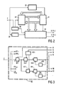
- FIG. 2 shows an exemplary embodiment of an estimation device allowing the implementation of all of this procedure.
- the device shown comprises an input connection E on which the digital samples constituting the input image appear (for example at a sampling frequency equal to 13.5 megahertz in the case of a video image).
- the input image is sent on the one hand to an image memory 10, to which is entrusted the role of saving the previous image during the processing of the current image.
- An image delay circuit 20 is therefore placed between the connection E and the input of the image memory 10.
- the input image is also sent to a line delay circuit 30, which allows to access the current point of the previous line of the current image (in the case of the blocks discovered in the third group).
- the I successive lines of the image which each constitute a line of a block are also stored in a memory circuit 60 which allows access to the current line of the blocks.
- the input image is finally sent to a recursive displacement estimator 40 which updates with each extension of the classification tree the displacement vectors relating to the nodes of the tree.
- displacement vectors are then sent, in number M, to a delayed decision circuit 50 which chooses the best one, according to the majority decision process mentioned above, as being the displacement estimation of the block considered, this circuit 50 thus determining a group and a displacement vector per block of image sequence, but this decision intervening with L blocks of delay.
- the image memory 10 intended to allow access to the blocks of the previous image taking into account the displacement vector receives from the recursive displacement estimator 40 the M displacement vectors (the same as those sent to the circuit 50) concerning the M successive nodes of the classification tree and provides it with a sampling period later, after indirect addressing, the brightness of the homologous points of the new point X representative of the current block, the designation X symbolizing the coordinates m, n of this point representative of the current block, that is to say of the points X-DEP1, X-DEP-2, ..., X-DEPM of the previous image.
- the memory 10 also provides the circuit 50 with this brightness of said homologous points.
- FIG. 3 gives an exemplary embodiment of the recursive displacement estimator 40.
- This estimator 40 comprises M similar circuits each operating on one of the M outputs of the image memory 10, and therefore only one will be described of these circuits, composed of the elements 401i to 415i (i varying from 1 to M).
- a subtractor 401i receives on the one hand on its positive input for example the input image present on the input connection E and on the other hand on its negative input the output of the image memory 10, it is ie the i-th brightness, and delivers as difference signal the difference in brightness between the point X representative of the current block and the homologous point X-DEPi of the previous image.
- This output signal from the subtractor 401i is sent to two multipliers 402i and 412i which produce the product by the spatial gradient of the brightness at the point X-DEPi, itself delivered in vector form (gradient in the direction m, gradient in the direction n) by a gradient circuit 403i which operates on the brightness of the neighboring points A, B, C, D of the point X-DEPi read in the image memory 10.
- a gradient circuit 403i which operates on the brightness of the neighboring points A, B, C, D of the point X-DEPi read in the image memory 10.
- the vector output signal of the multipliers which is the estimation error as specified above, is then processed by two recursive filters without weighting comprising respectively a subtractor 404i and 414i and a point delay circuit 405i and 415i.
- the circuit 405i (or 415i) receives the output of the subtractor 404i (or 414i) and reintroduces it, delayed, on the negative input of the latter, whose positive input receives said estimation error and delivers the new displacement vector associated with the point X representative of the current block considered.
- the vectors DEP1, DEP2, ..., DEPM thus updated are sent on the one hand, for addressing, to the image memory 10, where they take the place of the previous ones, and on the other hand to the decision circuit at delay 50, shown in Figure 5 in a particular embodiment according to the invention.
- This circuit 50 comprises first of all (M + 2) subtractor circuits 501, 502, and 50 (1) to 50 (M) which calculate the classification errors, by evaluation of the difference in brightness between the points of the image previous and the points of the current image, except for the subtractor 502 where this difference is evaluated between the points from the previous line and those from the current line; the numbers in parentheses designate in the references 50 (1) to 50 (M) the nodes of the classification tree.
- circuits 51 (1) to 51 (M) are then squared in the (M + 2) circuits 511, 512, and 51 (1) to 51 (M).
- the outputs of circuits 51 (1) to 51 (M) are sent to 3M accumulators making it possible to obtain the sum of classification errors for all the image points which form the current block.
- circuits 521 (1) to 521 (M) are followed by circuits 521 (1) to 521 (M).
- the output of these square elevation circuits is indeed sent to 3M first adders 521 (1) to 521 (M), 522 (1) to 522 (M), 523 (1) to 523 (M) in the way following: 511 to 521 (1) to 521 (M), 512 to 522 (1) to 522 (M), 51 (1) to 51 (M) to 523 (1) to 523 (M) respectively.
- the 3M adders receive on their other input the distortions of the nodes present at the output of M delay circuits 54 (1) to 54 (M) themselves preceded by M adders 53 (1) to 53 (M). The role of these delay
- the output signals of the first 3M adders then represent the cumulative distortions of the 3M branches, before elimination of 2M branches of greatest distortion, and are sent to the sorting circuit 590.
- the latter is responsible for sorting, among these 3M signals received, those which represent the M lowest cumulative distortion values and send them to the first respective inputs of M adders 53 (1) to 53 (M), and deliver in addition to these M distortion values and in correspondence with each d 'they have an index corresponding to the classification they have at the entrance to the sorting circuit.
- This circuit 600 comprises in the present case a decoder circuit 601 which extracts the two pieces of information of branch number (from which the group is deduced) and of node number, for example at using a ROM memory (read only memory can only be read; in English Read-Only Memory) programmed to provide for each address between 1 and 3M a quotient and a remainder calculated as indicated below: after increasing each index by 2 and dividing each index (thus increased) by three, we deduce (a) the quotient, which indicates the node number (between 1 and M) of the last level of the classification tree and (b) the rest, which is equal to 1/3, 0, or 2 / 3, values to which the group of the branch to which the distortion is associated respectively is corresponded, that is to say the first group of fixed blocks, the second group of mobile blocks, or the third group of discovered blocks.
- a decoder circuit 601 which extracts the two pieces of information of branch number (from which the group is deduced) and of node number, for example at using a
- the backup and update circuit also includes 2M main registers 602 (1), 602 (2), ..., 602 (M), 603 (1), 603 (2), ..., 603 (M ), and 2M auxiliary registers 612 (1), 612 (2), ..., 612 (M), 613 (1), 613 (2), ..., 613 (M).
- These 4M shift registers each contain L boxes intended for L words relating to the length (that is to say to the number of levels) of the classification tree.
- the first of these registers (that is to say the 2M main registers) memorize the information which relates to the most recent level (that is to say the point X representative of the current block of the image) and thus right now.
- the M main registers 602 (1) to 602 (M) and the M auxiliary registers 612 (1) to 612 (M) store the displacement vectors for the L successive levels of the classification tree, while the M main registers 603 (1) to 603 (M) and the M auxiliary registers 613 (1) to 613 (M) likewise store for the L successive levels the group information of the surviving branches.
- the content of these registers allows the classification tree to be reconfigured so that the nodes are arranged in descending order of their distortion, this reconfiguration being carried out as will be explained in more detail.
- the contents of the 2M main registers 602 (1) to 602 (M) and 603 (1) to 603 (M) are transferred respectively to the 2M auxiliary registers 612 (1) to 612 (M ) and 613 (1) to 613 (M) to save the classification tree before its reorganization.
- This transfer makes the 2M main registers ready to receive the new configuration of the classification tree, without losing the old one.
- the contents of the 2M auxiliary registers 612 (1) to 612 (M) and 613 (1) to 613 (M) are returned via the multiplexers 621 and 622 (621 for the displacement vectors, 622 for group information) to 2M main registers 602 (1) to 602 (M) and 603 (1) to 603 (M), in order to arrange said contents in the main registers in descending order of the associated distortions.
- the main registers 602 (K) and 603 (K) for example, contain, after such transfer operations, respectively the displacement vectors and the groups of the tree branch whose distortion is the K-th in the descending order of these.
- a delayed decision will then be taken by the majority decision circuit 630.
- This circuit indeed examines the L-th words of the M main registers 603 (1) to 603 (M) and determines the group whose number of occurrences is the largest (that is, the group that comes up most often). If it is then register 603 (K), for example, which stores this group, the contents of the L-th word of the main registers 603 (K) and 602 (K) are considered to be group G (XL) respectively. and the displacement vector D (XL) of the block XL. It is these two pieces of information which are provided at the output of the majority decision circuit 630, that is to say, in fact, at the output of circuit 50 as indicated in FIG. 2.
- the cumulative distortion is given an infinite value, or at least very large, for example by adding a value greater than the maximum brightness of the scanned image.
- Output signals 615 (1) to 615 (M) of circuit 600 which are equal to the maximum brightness for branches to be erased and zero for the others, are sent to the respective second inputs of the M adders 53 (1) to 53 (M) followed by delay circuits 54 (1) to 54 (M) respectively. These delay circuits delay the signals passing through them by a sampling period.
- the final decision is now taken, the words of the 2M main registers 602 (1) to 602 (M) and 603 (1) to 603 (M) are shifted down, and these registers are ready for a new decision operation at delay, each decision being of course followed by a shift of one unit from the main and auxiliary registers.
Landscapes
- Engineering & Computer Science (AREA)
- Multimedia (AREA)
- Signal Processing (AREA)
- Computer Vision & Pattern Recognition (AREA)
- Physics & Mathematics (AREA)
- General Physics & Mathematics (AREA)
- Theoretical Computer Science (AREA)
- Compression Or Coding Systems Of Tv Signals (AREA)
- Image Analysis (AREA)
- Color Television Systems (AREA)
Priority Applications (1)
| Application Number | Priority Date | Filing Date | Title |
|---|---|---|---|
| AT88200650T ATE71750T1 (de) | 1987-04-10 | 1988-04-06 | Verfahren und geraet zur bewegungsabschaetzung in einer bildfolge. |
Applications Claiming Priority (2)
| Application Number | Priority Date | Filing Date | Title |
|---|---|---|---|
| FR8705121A FR2613892A1 (fr) | 1987-04-10 | 1987-04-10 | Procede et dispositif d'estimation de mouvement dans une sequence d'images |
| FR8705121 | 1987-04-10 |
Publications (2)
| Publication Number | Publication Date |
|---|---|
| EP0286192A1 true EP0286192A1 (de) | 1988-10-12 |
| EP0286192B1 EP0286192B1 (de) | 1992-01-15 |
Family
ID=9350013
Family Applications (1)
| Application Number | Title | Priority Date | Filing Date |
|---|---|---|---|
| EP88200650A Expired - Lifetime EP0286192B1 (de) | 1987-04-10 | 1988-04-06 | Verfahren und Gerät zur Bewegungsabschätzung in einer Bildfolge |
Country Status (6)
| Country | Link |
|---|---|
| US (1) | US4875094A (de) |
| EP (1) | EP0286192B1 (de) |
| JP (1) | JPS63263884A (de) |
| AT (1) | ATE71750T1 (de) |
| DE (1) | DE3867674D1 (de) |
| FR (1) | FR2613892A1 (de) |
Families Citing this family (10)
| Publication number | Priority date | Publication date | Assignee | Title |
|---|---|---|---|---|
| FR2623955B1 (fr) * | 1987-11-27 | 1990-04-27 | Labo Electronique Physique | Procede et dispositif d'estimation et de compensation de mouvement dans une sequence d'images et leur application dans un systeme de transmission d'images de television a haute definition |
| US4933757A (en) * | 1988-08-20 | 1990-06-12 | Olympus Optical Co., Ltd. | Electronic endoscope apparatus provided with a movement detecting means |
| JP2828105B2 (ja) * | 1988-10-27 | 1998-11-25 | オリンパス光学工業株式会社 | 動き検出回路 |
| JP2861249B2 (ja) * | 1989-05-11 | 1999-02-24 | 日本電気株式会社 | 画像変化検出方法および画像変化検出装置 |
| JP2520306B2 (ja) * | 1989-05-24 | 1996-07-31 | 三菱電機株式会社 | 変換符号化装置 |
| US5140417A (en) * | 1989-06-20 | 1992-08-18 | Matsushita Electric Co., Ltd. | Fast packet transmission system of video data |
| JPH0832048B2 (ja) * | 1990-01-23 | 1996-03-27 | 日本ビクター株式会社 | 動きベクトル検出装置 |
| US5309237A (en) * | 1992-03-31 | 1994-05-03 | Siemens Corporate Research, Inc. | Apparatus and method of compensating image-sequences for motion |
| US5430886A (en) * | 1992-06-15 | 1995-07-04 | Furtek; Frederick C. | Method and apparatus for motion estimation |
| GB2362533A (en) * | 2000-05-15 | 2001-11-21 | Nokia Mobile Phones Ltd | Encoding a video signal with an indicator of the type of error concealment used |
Citations (1)
| Publication number | Priority date | Publication date | Assignee | Title |
|---|---|---|---|---|
| FR2590701A1 (fr) * | 1985-11-22 | 1987-05-29 | Labo Electronique Physique | Procede et dispositif d'estimation de mouvement dans une sequence d'images |
Family Cites Families (5)
| Publication number | Priority date | Publication date | Assignee | Title |
|---|---|---|---|---|
| US4245248A (en) * | 1979-04-04 | 1981-01-13 | Bell Telephone Laboratories, Incorporated | Motion estimation and encoding of video signals in the transform domain |
| JPS60158786A (ja) * | 1984-01-30 | 1985-08-20 | Kokusai Denshin Denwa Co Ltd <Kdd> | 画像動き量検出方式 |
| JPS61200789A (ja) * | 1985-03-04 | 1986-09-05 | Kokusai Denshin Denwa Co Ltd <Kdd> | 画面上の物体の動きベクトル検出方式 |
| US4703350A (en) * | 1985-06-03 | 1987-10-27 | Picturetel Corporation | Method and apparatus for efficiently communicating image sequences |
| US4779131A (en) * | 1985-07-26 | 1988-10-18 | Sony Corporation | Apparatus for detecting television image movement |
-
1987
- 1987-04-10 FR FR8705121A patent/FR2613892A1/fr not_active Withdrawn
-
1988
- 1988-04-06 AT AT88200650T patent/ATE71750T1/de not_active IP Right Cessation
- 1988-04-06 EP EP88200650A patent/EP0286192B1/de not_active Expired - Lifetime
- 1988-04-06 DE DE8888200650T patent/DE3867674D1/de not_active Expired - Lifetime
- 1988-04-08 JP JP63085500A patent/JPS63263884A/ja active Pending
- 1988-04-08 US US07/179,109 patent/US4875094A/en not_active Expired - Fee Related
Patent Citations (1)
| Publication number | Priority date | Publication date | Assignee | Title |
|---|---|---|---|---|
| FR2590701A1 (fr) * | 1985-11-22 | 1987-05-29 | Labo Electronique Physique | Procede et dispositif d'estimation de mouvement dans une sequence d'images |
Non-Patent Citations (1)
| Title |
|---|
| COMPUTER VISION, GRAPHICS, AND IMAGE PROCESSING, vol. 21, no. 2, février 1983, pages 262-279, Academic Press Inc., New York, US; M. YACHIDA: "Determining velocity maps by spatio-temporal neighborhoods from image sequences" * |
Also Published As
| Publication number | Publication date |
|---|---|
| FR2613892A1 (fr) | 1988-10-14 |
| US4875094A (en) | 1989-10-17 |
| DE3867674D1 (de) | 1992-02-27 |
| EP0286192B1 (de) | 1992-01-15 |
| JPS63263884A (ja) | 1988-10-31 |
| ATE71750T1 (de) | 1992-02-15 |
Similar Documents
| Publication | Publication Date | Title |
|---|---|---|
| EP0286192B1 (de) | Verfahren und Gerät zur Bewegungsabschätzung in einer Bildfolge | |
| EP0492702A1 (de) | Korrelationsvorrichtung | |
| EP0341769B1 (de) | Bildinterpolierungsgerät mit Bewegungsabschätzung und Kompensation und aus einem solchen Gerät bestehendes Konvertierungssystem für Fernsehstandards | |
| EP0224957B1 (de) | Verfahren und Einrichtung zur Bewegungsabschätzung in einer Bildfolge | |
| FR2674653A1 (fr) | Procede et dispositif de detection de bord pour un systeme de traitement d'image. | |
| EP0473476A1 (de) | Verfahren und Vorrichtung zur Realzeit-Lokalisierung von geraden Kanten in einem numerischen Bild, insbesondere für die Mustererkennung in einem Szenenanalyseprozess | |
| EP0255177A1 (de) | Verfahren zur automatischen Extraktion eines kontrastierten Gegenstands in einem digitalen Bild | |
| EP0142439A2 (de) | Verfahren zur Kompression einer Folge digitaler Informationen und Vorrichtung dafür | |
| EP0237115A1 (de) | Verfahren zur Flankenversteilerung von digitalen Signalen und Vorrichtung zum Durchführen dieses Verfahrens | |
| EP0717372B1 (de) | Verfahren zum Auswählen von Bewegungsvektoren und Bildverarbeitungsvorrichtung zur Durchführung des Verfahrens | |
| EP0318121B1 (de) | Verfahren und Vorrichtung zum Abschätzen und Kompensieren der Bewegung in einer Bildsequenz und Bildtransmissionssystem mit einer solchen Vorrichtung | |
| EP0619552B1 (de) | Verfahren und Vorrichtung zur Bestimmung von Objektbewegungen in hintereinanderfolgenden, animierten, in zweidimensionale Bildelementblöcke geteilten Bildern | |
| EP0332553A1 (de) | Verfahren zur Wiederzuordnung der Wahl eines Unterabtastungsverfahrens nach dem Kriterium einer Datenraten-Reduktion einer Folge von Hilfsdaten, die zur Rekonstruktion eines unterabgetasteten, elektronischen Bildes dienen | |
| EP0410826A1 (de) | Iteratives Bewegungsabschätzungsverfahren zwischen einem Referenzbild und einem aktuellen Bild, und Verfahren zu ihrer Herstellung | |
| EP0123573B1 (de) | Verfahren zum adaptiven Kodieren und Dekodieren eines Fernsehbildes und Vorrichtung zur Durchführung dieses Verfahrens | |
| FR2684829A1 (fr) | Methodes de synthese de signaux de texture et de transmission et/ou stockage de tels signaux, ainsi que dispositifs et systemes pour leur mise en óoeuvre. | |
| EP0457639A1 (de) | Verfahren und Vorrichtung zur Korrektur von Bildern, die aus einem periodischen rauscherzeugenden Sensor erhalten werden | |
| WO1988010046A1 (fr) | Procede et dispositif d'interpolation temporelle d'images | |
| Narendra | Scene-based nonuniformity compensation for imaging sensors | |
| EP0255419B1 (de) | Verfahren zur Bestimmung und Beschreibung von Konturen eines Bildes und Vorrichtung zum Ausführen dieses Verfahrens | |
| FR2575879A1 (fr) | Filtre passe-bas pour images numerisees et dispositifs comportant un tel filtre | |
| EP1095358B1 (de) | Verfahren zur modellierung von gegenständen oder dreidimensionalen szenen | |
| FR2595175A1 (fr) | Procede et dispositif pour determiner un " m-tile " souhaite d'un certain nombre d'echantillons numeriques | |
| EP0524871B1 (de) | Verfahren zur adaptiven hybriden Kodierung von Signalen | |
| WO1995025404A1 (fr) | Procede et dispositif d'estimation de mouvement entre images de television d'une sequence d'images |
Legal Events
| Date | Code | Title | Description |
|---|---|---|---|
| PUAI | Public reference made under article 153(3) epc to a published international application that has entered the european phase |
Free format text: ORIGINAL CODE: 0009012 |
|
| AK | Designated contracting states |
Kind code of ref document: A1 Designated state(s): AT DE FR GB IT |
|
| 17P | Request for examination filed |
Effective date: 19890403 |
|
| RAP1 | Party data changed (applicant data changed or rights of an application transferred) |
Owner name: LABORATOIRES D'ELECTRONIQUE PHILIPS Owner name: N.V. PHILIPS' GLOEILAMPENFABRIEKEN |
|
| 17Q | First examination report despatched |
Effective date: 19910319 |
|
| GRAA | (expected) grant |
Free format text: ORIGINAL CODE: 0009210 |
|
| AK | Designated contracting states |
Kind code of ref document: B1 Designated state(s): AT DE FR GB IT |
|
| PG25 | Lapsed in a contracting state [announced via postgrant information from national office to epo] |
Ref country code: IT Free format text: LAPSE BECAUSE OF FAILURE TO SUBMIT A TRANSLATION OF THE DESCRIPTION OR TO PAY THE FEE WITHIN THE PRE;WARNING: LAPSES OF ITALIAN PATENTS WITH EFFECTIVE DATE BEFORE 2007 MAY HAVE OCCURRED AT ANY TIME BEFORE 2007. THE CORRECT EFFECTIVE DATE MAY BE DIFFERENT FROM THE ONE RECORDED.SCRIBED TIME-LIMIT Effective date: 19920115 Ref country code: AT Effective date: 19920115 |
|
| REF | Corresponds to: |
Ref document number: 71750 Country of ref document: AT Date of ref document: 19920215 Kind code of ref document: T |
|
| REF | Corresponds to: |
Ref document number: 3867674 Country of ref document: DE Date of ref document: 19920227 |
|
| GBT | Gb: translation of ep patent filed (gb section 77(6)(a)/1977) | ||
| PLBE | No opposition filed within time limit |
Free format text: ORIGINAL CODE: 0009261 |
|
| STAA | Information on the status of an ep patent application or granted ep patent |
Free format text: STATUS: NO OPPOSITION FILED WITHIN TIME LIMIT |
|
| 26N | No opposition filed | ||
| REG | Reference to a national code |
Ref country code: FR Ref legal event code: CD Ref country code: FR Ref legal event code: CJ |
|
| PGFP | Annual fee paid to national office [announced via postgrant information from national office to epo] |
Ref country code: GB Payment date: 19960329 Year of fee payment: 9 |
|
| PGFP | Annual fee paid to national office [announced via postgrant information from national office to epo] |
Ref country code: FR Payment date: 19960429 Year of fee payment: 9 |
|
| PGFP | Annual fee paid to national office [announced via postgrant information from national office to epo] |
Ref country code: DE Payment date: 19960625 Year of fee payment: 9 |
|
| PG25 | Lapsed in a contracting state [announced via postgrant information from national office to epo] |
Ref country code: GB Effective date: 19970406 |
|
| GBPC | Gb: european patent ceased through non-payment of renewal fee |
Effective date: 19970406 |
|
| PG25 | Lapsed in a contracting state [announced via postgrant information from national office to epo] |
Ref country code: FR Free format text: LAPSE BECAUSE OF NON-PAYMENT OF DUE FEES Effective date: 19971231 |
|
| PG25 | Lapsed in a contracting state [announced via postgrant information from national office to epo] |
Ref country code: DE Free format text: LAPSE BECAUSE OF NON-PAYMENT OF DUE FEES Effective date: 19980101 |
|
| REG | Reference to a national code |
Ref country code: FR Ref legal event code: ST |