EP0286156B1 - Grate with pushers for the combustion of solid materials - Google Patents
Grate with pushers for the combustion of solid materials Download PDFInfo
- Publication number
- EP0286156B1 EP0286156B1 EP88200488A EP88200488A EP0286156B1 EP 0286156 B1 EP0286156 B1 EP 0286156B1 EP 88200488 A EP88200488 A EP 88200488A EP 88200488 A EP88200488 A EP 88200488A EP 0286156 B1 EP0286156 B1 EP 0286156B1
- Authority
- EP
- European Patent Office
- Prior art keywords
- elements
- grate
- stationary
- moving
- pushers
- Prior art date
- Legal status (The legal status is an assumption and is not a legal conclusion. Google has not performed a legal analysis and makes no representation as to the accuracy of the status listed.)
- Expired - Lifetime
Links
- 238000002485 combustion reaction Methods 0.000 title claims abstract description 29
- 239000011343 solid material Substances 0.000 title claims description 14
- 239000000463 material Substances 0.000 claims abstract description 26
- 230000000295 complement effect Effects 0.000 claims description 8
- 239000002699 waste material Substances 0.000 claims description 4
- 238000007789 sealing Methods 0.000 claims description 3
- 239000007787 solid Substances 0.000 claims description 3
- 239000006185 dispersion Substances 0.000 claims 1
- 238000001816 cooling Methods 0.000 abstract 1
- 239000002184 metal Substances 0.000 description 4
- 229910052751 metal Inorganic materials 0.000 description 4
- 239000000428 dust Substances 0.000 description 3
- 238000002844 melting Methods 0.000 description 2
- 230000035515 penetration Effects 0.000 description 2
- 230000001464 adherent effect Effects 0.000 description 1
- 230000015572 biosynthetic process Effects 0.000 description 1
- 238000010276 construction Methods 0.000 description 1
- 238000009792 diffusion process Methods 0.000 description 1
- 230000008030 elimination Effects 0.000 description 1
- 238000003379 elimination reaction Methods 0.000 description 1
- 239000004744 fabric Substances 0.000 description 1
- 230000003993 interaction Effects 0.000 description 1
- 230000001788 irregular Effects 0.000 description 1
- 239000007769 metal material Substances 0.000 description 1
- 150000002739 metals Chemical class 0.000 description 1
- 239000002245 particle Substances 0.000 description 1
- 238000000926 separation method Methods 0.000 description 1
- 238000007493 shaping process Methods 0.000 description 1
Images



Classifications
-
- F—MECHANICAL ENGINEERING; LIGHTING; HEATING; WEAPONS; BLASTING
- F23—COMBUSTION APPARATUS; COMBUSTION PROCESSES
- F23H—GRATES; CLEANING OR RAKING GRATES
- F23H15/00—Cleaning arrangements for grates; Moving fuel along grates
-
- F—MECHANICAL ENGINEERING; LIGHTING; HEATING; WEAPONS; BLASTING
- F23—COMBUSTION APPARATUS; COMBUSTION PROCESSES
- F23H—GRATES; CLEANING OR RAKING GRATES
- F23H1/00—Grates with solid bars
- F23H1/02—Grates with solid bars having provision for air supply or air preheating, e.g. air-supply or blast fittings which form a part of the grate structure or serve as supports
Definitions
- the present invention relates to a grate with pushers for the combustion of solid materials.
- the grate Besides performing the function of supporting and moving forwards the material treated, the grate must make possible the combustion air to be injected, and at the same time carefully distributed, inside said material.
- GB-A-164 914 shows a grate for combustion of solid material, comprising stationary elements of box-like shape for supporting the material and moving elements for moving the material to be treated, wherein the surface area in contact with said material of said stationary elements is larger than that of said moving elements, inside said stationary elements a combustion air feed channel being provided for feeding the combustion air outwards.
- Such a grate known from the prior art shows faults due to the ease of occlusion of the air feed openings, to the penetration of dusts composed by fine material particles under the same grate, to the adhesion of low-melting metal materials and to the wear occurring in the moving and stationary components, caused by the operation type, and by the same structure thereof.
- a purpose of the present invention is to provide a grate with pushers capable of solving all of the above problems, while remaining extremely flexible as to its function, and able to treat solid material types of very different nature.
- a grate with pushers for the combustion of solid materials, in particular solid urban wastes characterized in that said combustion air feed channel terminates at a hollow provided at the bottom on a front outwards-facing portion of said stationary element, inside said hollow a complementary projection being slidingly guided, which is provided in an upper portion of said moving elements in such a way as to leave free, in its rest position, an opening acting as an outlet for said combustion air feed channel.
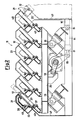
- the solid material is fed above a set of sectors 11 of grates with pushers having a structure according to the present invention.
- Each grate sector 11 is fed at its bottom with combustion air from a hopper 13 of its own, the flow rate of air streaming through which is adjustable according to as needed by the individual sector wherein a specific step of the incinerating or combustion process takes place.
- the means are furthermore shown, which are provided for the purpose of moving the whole of movable pusher elements 12, also denominated moving elements, of each individual sector 11, interposed and alternated with as many step elements 21 also denominated stationary elements.
- Said moving means are schematically shown in the form of a cylinder 14, e.g. an oleodynamic cylinder, fastened through a pin 15 onto a frame 16 of the incinerating furnace, said cylinder moving, by means of a stem 17, with the interposition of a bell crank 18 and of relevant guide rollers 19 (Fig. 2), a longitudinal support beam 20, with which the pusher elements 12 are integral.
- a cylinder 14 e.g. an oleodynamic cylinder
- Figs. 2, 3 and 4 the elements composing the grate with pushers are shown in greater detail.
- an equal number of stationary step elements 21 are positioned on each one of a plurality of stationary beams 22, transversal relatively to the travelling direction of the material, and essentially parallel to the upper surface of the grate.
- each individual beam 22 and each stationary step element 21 is accomplished by means of an end bar 23 which is engaged inside a perforated bracket 24, integral with the beam 22, and which receives bent, hook-like shaped portions 25 which extend downwards under the step element 21.
- the bent, hook-like shaped portions 25 extend, on their side close to the beam 22, into a further portion 27 having a length nearly equalling the width of the same beam, so to interact with an adjustment element 28, such as a screw, provided inside the beam 22, and which acts as a stop.
- an adjustment element 28 such as a screw, provided inside the beam 22, and which acts as a stop.
- the step element 21, of box-like shape is provided, in its interior, with a channel 29, defined by a wall 30 which runs parallelly to the outer profile of the same step element, and which contains in its interior a set of heat-diffusion fins 31, which extend downwards from said outer profile, parallelly to the direction of channel 29.
- Channel 29 extends up to come in the nearby of a flat portion 32, bent inwards from a front wall 40 of the step element 21 parallelly to the pusher element 12, which defines, with the wall 30, an opening 33 acting as an air outlet.
- the step element 21 is provided, in a central portion thereof, a hollow 34 capable of receiving, and allowing the sliding of, a projection 35 of complementary shape, provided above each pusher element 12.
- the projection 35 is provided only in an upper central portion of the pusher element 12, so to be aligned with the outlet opening 33, leaving it completely free when the pusher element is in its rest position.
- the pusher element 12 which too results to be of box-like shape, but of a height much lower than of the step element 21, has preferably a flattened parallelepipedal shape. At its bottom, it is provided with a flat front portion, bent rearwards, 41, which extends from a front wall 42 lined-up with the front wall 40 of the step element 21. In a rear portion thereof, the pusher element 12 is provided with portions bent to a hook-like shape 36, which engage themselves above an end bar 37 inserted inside a perforated bar 38 integral with the stationary beam 43 in a way analogous to the step element 21.
- the pusher element 12 is provided with a couple of appendices 39, whose bottom portion extends downwards inside the pusher element 12, said appendices 39 being parallel to the hook-like bent portions 36 and coming to position themselves on opposite sides relatively to the perforated bracket 38, so to keep the pusher element 12 centered.
- the hook-like bent portions 36 in correspondence of their side placed in the nearby of further beams 43 integral with the longitudinal support beam 20, extend into a further portion 44 which has a dimension larger than the width of the further beams 43, so to interact with an adjustment element 45, e.g., a screw element, positioned integral with the same beams 43, and acting as an adjustable stop element.
- an adjustment element 45 e.g., a screw element
- Both the pusher elements 12 and the step elements 21 are provided with perimetral undercuts or surmount elements 46 of complementary shape, capable of securing a tight sealing between the various elements, thus preventing undesired flows of air and dust materials.
- a shaped metal sheet 47 is provided for acting as a closure element; it, together with further closure elements 48, e.g., elastic metal sheet, or waterproof cloth, positioned between the beams 22 and the upper end portion of the step element 21 facing the same beams, secure the separation of the air streams fed to the individual sectors.
- closure elements 48 e.g., elastic metal sheet, or waterproof cloth
- the pusher elements 12 and the step elements 21, e.g., in a number of six, define a sector of treatment of the solid materials to be incinerated, wherein the pusher elements 12, supported by the beams 43 and by the beam 20, essentially perform the function of moving the material, whilst the step elements 21, integral with the beams 22, act as supports for the material.
- the step elements 21, which have a large surface area in contact with the material to be treated and the pusher elements 12 which, besides having a minimum surface area in contact with the material, in their rest position expose to said material only their small push surface area, and are hidden under the stationary elements 21.
- the geometry of the step element/pusher element assembly which in Figure 2 results inclined by 45° relatively to the support beam 20, can be also varied according to other indications for the push angle ⁇ defined between the same beam 20 and the direction of the pusher element.
- the particular canalization of the combustion air which licks up the whole surface of the step element 21, also thanks to the presence of the fins 31, suitably cools the same step element, and at the same time heats the combustion air improving the incinerating treatment.
- the channel 29 and the projection 35 make it also possible to control the flowrate of the combustion air.
- the projection 35 constitutes a rear closure element for the channel 29 when the pusher element 12 is in its rest position. It is thus evident how, by adjusting the position of the projection 35 relatively to the outlet opening 33, the amount of combustion air being fed can be varied as desired.
- a grate is thus obtained, which make it possible to change as desired the pressure drop occurring in the air stream, so that the distribution of air on the grate can be controlled mainly as a function of the geometry of the grate, rather than of the distribution of the solid material on the grate.
- the very important result is achieved of having very high pressure drops also in the presence of small air flowrates under the grate, thus the air waste being avoided, which is caused by the forming of preferential chimneys, above all when the combustion requires low thicknesses of materials to be incinerated on the grate.
- Another function of paramount importance of the projection 35 is that of keeping clean the outlet opening 33 of the channel 29, as well as the hollow 34, securing the flow of air, and at the same time generating a compact and powerful air jet.
- Furtnermore, the projection 35 is of such a length as to prevent material from being entrained into the inside of the channel 29 during the movement of return of the pusher element 12.
- the function of the projection 35 as an element for stopping the flow of air coming through the channel 29 during the operative movement of the pusher element 12 for moving the solid material to be incinerated.
- This positioning offers the advantage of not causing flames to be generated in the nearby of the metal parts constituting the grate, which result hence protected exactly by the same solid material which is being treated.
- the pusher element 12 positioned nearly in correspondence with the end surfaces of the two step elements between which it is comprised, shows a small surface area of sliding contact and friction on the same step element, so that both the elements 12 and 21 undergo a lower wear.
- molten masses occur often, which adhere to the stationary elements 21 supporting surfaces. These molten masses, which result in the formation of nodules strongly adherent to the plates, disturb, or even sometimes prevent the regular movement of the movable elements 12.
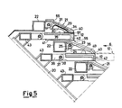
- a projection 55 ( Figure 5) is provided, which protrudes outwards, frontally, and atop, from the stationary element 21, so that, thanks to such a shaping of the stationary element 21, the moving pusher element 12 moves forwards in a cantilevering position in the material, so to prevent such a drawback.
- pusher element 12 can act on a layer of solid material to be treated larger than that treated by the grate as shown in Figures from 2 to 4, by protruding from two consecutive step elements by a considerable length, in its extracted pushing position.
- the opening cross surface area of the hollow 34 can be limited by means of shimming elements 51 to be integrally positioned above the underlying pusher elements 12 in the free area in front of the projection 35, so to keep constant the outflow speed, also in grate sections with reduced air flowrates.
- the stationary elements 21 can be preferably provided with appendices 27, as shown in Figure 3, whilst for the moving pusher elements 12, the limitation of the angular movement on the vertical plane, whose adjustment takes place during the assemblage step, is achieved by means of two rear appendices 36 which come to stop against a side of beam 43.
Landscapes
- Engineering & Computer Science (AREA)
- Chemical & Material Sciences (AREA)
- Combustion & Propulsion (AREA)
- Mechanical Engineering (AREA)
- General Engineering & Computer Science (AREA)
- Incineration Of Waste (AREA)
- Fertilizers (AREA)
- Housing For Livestock And Birds (AREA)
- Agricultural Chemicals And Associated Chemicals (AREA)
- Preventing Corrosion Or Incrustation Of Metals (AREA)
- Catalysts (AREA)
- Baking, Grill, Roasting (AREA)
- Solid Fuels And Fuel-Associated Substances (AREA)
Priority Applications (1)
| Application Number | Priority Date | Filing Date | Title |
|---|---|---|---|
| AT88200488T ATE63785T1 (de) | 1987-03-24 | 1988-03-17 | Rost mit stoessel fuer die verbrennung von feststoffen. |
Applications Claiming Priority (2)
| Application Number | Priority Date | Filing Date | Title |
|---|---|---|---|
| IT19819/87A IT1202677B (it) | 1987-03-24 | 1987-03-24 | Griglia a spintori per la combustione di materiali solidi |
| IT1981987 | 1987-03-24 |
Publications (2)
| Publication Number | Publication Date |
|---|---|
| EP0286156A1 EP0286156A1 (en) | 1988-10-12 |
| EP0286156B1 true EP0286156B1 (en) | 1991-05-22 |
Family
ID=11161539
Family Applications (1)
| Application Number | Title | Priority Date | Filing Date |
|---|---|---|---|
| EP88200488A Expired - Lifetime EP0286156B1 (en) | 1987-03-24 | 1988-03-17 | Grate with pushers for the combustion of solid materials |
Country Status (6)
| Country | Link |
|---|---|
| EP (1) | EP0286156B1 (it) |
| AT (1) | ATE63785T1 (it) |
| DE (1) | DE3862888D1 (it) |
| ES (1) | ES2022591B3 (it) |
| GR (1) | GR3002314T3 (it) |
| IT (1) | IT1202677B (it) |
Families Citing this family (1)
| Publication number | Priority date | Publication date | Assignee | Title |
|---|---|---|---|---|
| US5323717A (en) * | 1992-12-04 | 1994-06-28 | Leon Industries, Inc. | Refuse feed assembly for incinerators |
Family Cites Families (1)
| Publication number | Priority date | Publication date | Assignee | Title |
|---|---|---|---|---|
| GB164914A (en) * | 1920-04-14 | 1921-06-23 | Joseph Martin | An improved method and apparatus for burning solid fuels |
-
1987
- 1987-03-24 IT IT19819/87A patent/IT1202677B/it active
-
1988
- 1988-03-17 AT AT88200488T patent/ATE63785T1/de not_active IP Right Cessation
- 1988-03-17 ES ES88200488T patent/ES2022591B3/es not_active Expired - Lifetime
- 1988-03-17 EP EP88200488A patent/EP0286156B1/en not_active Expired - Lifetime
- 1988-03-17 DE DE8888200488T patent/DE3862888D1/de not_active Expired - Fee Related
-
1991
- 1991-07-15 GR GR91401019T patent/GR3002314T3/el unknown
Also Published As
| Publication number | Publication date |
|---|---|
| ATE63785T1 (de) | 1991-06-15 |
| IT8719819A0 (it) | 1987-03-24 |
| GR3002314T3 (en) | 1992-12-30 |
| IT1202677B (it) | 1989-02-09 |
| DE3862888D1 (de) | 1991-06-27 |
| ES2022591B3 (es) | 1991-12-01 |
| EP0286156A1 (en) | 1988-10-12 |
Similar Documents
| Publication | Publication Date | Title |
|---|---|---|
| US4870913A (en) | Grate cooler for cooling hot bulk material | |
| US3841242A (en) | Apparatus for burning waste matter | |
| US4676176A (en) | Furnace grate | |
| JP5523679B2 (ja) | 移送格子上にあるバラ荷層を移送、特に冷却する方法および装置 | |
| KR890005266B1 (ko) | 유동층 반응기 내부의 장치 | |
| US4099471A (en) | Apparatus for cleaning the air nozzles and regulating air flow thereto in chemical recovery boilers | |
| CN88102184A (zh) | 冶金熔炼设备预热炉料的炉料预热器 | |
| US4876972A (en) | Grate bar element for a sliding grate furnace for garbage incineration | |
| JPS58205015A (ja) | ごみ焼き火格子のための火格子ブロツク | |
| JPH063351B2 (ja) | 耐熱格子要素および格子 | |
| EP0286156B1 (en) | Grate with pushers for the combustion of solid materials | |
| JP2793039B2 (ja) | 冶金容器用可閉式出湯装置 | |
| JPH04214112A (ja) | ボイラ用火格子及び該火格子を有するボイラ | |
| GB1601067A (en) | Fluidized-bed combuster | |
| US4371115A (en) | Ring-gap nozzle | |
| DK0856716T3 (da) | Apparat til varmebehandling af gennemløbende plade- eller båndformede materialer | |
| AU2010223680B2 (en) | Casting nozzle for a horizontal continuous casting system | |
| JPH0455777B2 (it) | ||
| US3987738A (en) | Seal for a traveling grate | |
| GB2032590A (en) | A fluidised bed grate | |
| CA2070980C (en) | Sidewall guide for combustion grates | |
| JP2004037016A (ja) | 階段式ストーカ | |
| CA2249842A1 (en) | Process for incinerating solids on a water-cooled thrust combustion grate, and a grate plate and grate for accomplishing the process | |
| CZ291546B6 (cs) | Roštová deska | |
| JPS6357686B2 (it) |
Legal Events
| Date | Code | Title | Description |
|---|---|---|---|
| PUAI | Public reference made under article 153(3) epc to a published international application that has entered the european phase |
Free format text: ORIGINAL CODE: 0009012 |
|
| AK | Designated contracting states |
Kind code of ref document: A1 Designated state(s): AT BE CH DE ES FR GB GR LI LU NL SE |
|
| 17P | Request for examination filed |
Effective date: 19890606 |
|
| 17Q | First examination report despatched |
Effective date: 19900115 |
|
| GRAA | (expected) grant |
Free format text: ORIGINAL CODE: 0009210 |
|
| AK | Designated contracting states |
Kind code of ref document: B1 Designated state(s): AT BE CH DE ES FR GB GR LI LU NL SE |
|
| REF | Corresponds to: |
Ref document number: 63785 Country of ref document: AT Date of ref document: 19910615 Kind code of ref document: T |
|
| REF | Corresponds to: |
Ref document number: 3862888 Country of ref document: DE Date of ref document: 19910627 |
|
| ET | Fr: translation filed | ||
| PLBE | No opposition filed within time limit |
Free format text: ORIGINAL CODE: 0009261 |
|
| STAA | Information on the status of an ep patent application or granted ep patent |
Free format text: STATUS: NO OPPOSITION FILED WITHIN TIME LIMIT |
|
| 26N | No opposition filed | ||
| REG | Reference to a national code |
Ref country code: GR Ref legal event code: FG4A Free format text: 3002314 |
|
| EPTA | Lu: last paid annual fee | ||
| EAL | Se: european patent in force in sweden |
Ref document number: 88200488.0 |
|
| PGFP | Annual fee paid to national office [announced via postgrant information from national office to epo] |
Ref country code: GR Payment date: 19950222 Year of fee payment: 8 |
|
| PGFP | Annual fee paid to national office [announced via postgrant information from national office to epo] |
Ref country code: GB Payment date: 19950224 Year of fee payment: 8 |
|
| PGFP | Annual fee paid to national office [announced via postgrant information from national office to epo] |
Ref country code: LU Payment date: 19950301 Year of fee payment: 8 Ref country code: ES Payment date: 19950301 Year of fee payment: 8 |
|
| PGFP | Annual fee paid to national office [announced via postgrant information from national office to epo] |
Ref country code: BE Payment date: 19950306 Year of fee payment: 8 |
|
| PGFP | Annual fee paid to national office [announced via postgrant information from national office to epo] |
Ref country code: FR Payment date: 19950309 Year of fee payment: 8 Ref country code: CH Payment date: 19950309 Year of fee payment: 8 |
|
| PGFP | Annual fee paid to national office [announced via postgrant information from national office to epo] |
Ref country code: AT Payment date: 19950324 Year of fee payment: 8 |
|
| PGFP | Annual fee paid to national office [announced via postgrant information from national office to epo] |
Ref country code: DE Payment date: 19950328 Year of fee payment: 8 |
|
| PGFP | Annual fee paid to national office [announced via postgrant information from national office to epo] |
Ref country code: SE Payment date: 19950330 Year of fee payment: 8 |
|
| PGFP | Annual fee paid to national office [announced via postgrant information from national office to epo] |
Ref country code: NL Payment date: 19950331 Year of fee payment: 8 |
|
| PG25 | Lapsed in a contracting state [announced via postgrant information from national office to epo] |
Ref country code: LU Free format text: LAPSE BECAUSE OF NON-PAYMENT OF DUE FEES Effective date: 19960317 Ref country code: GB Effective date: 19960317 Ref country code: AT Effective date: 19960317 |
|
| PG25 | Lapsed in a contracting state [announced via postgrant information from national office to epo] |
Ref country code: SE Effective date: 19960318 Ref country code: ES Free format text: LAPSE BECAUSE OF NON-PAYMENT OF DUE FEES Effective date: 19960318 |
|
| PG25 | Lapsed in a contracting state [announced via postgrant information from national office to epo] |
Ref country code: LI Effective date: 19960331 Ref country code: CH Effective date: 19960331 Ref country code: BE Effective date: 19960331 |
|
| BERE | Be: lapsed |
Owner name: S.P.A. FORNI ED IMPIANTI INDUSTRIALI INGG. DE BAR Effective date: 19960331 |
|
| PG25 | Lapsed in a contracting state [announced via postgrant information from national office to epo] |
Ref country code: GR Free format text: THE PATENT HAS BEEN ANNULLED BY A DECISION OF A NATIONAL AUTHORITY Effective date: 19960930 |
|
| PG25 | Lapsed in a contracting state [announced via postgrant information from national office to epo] |
Ref country code: NL Effective date: 19961001 |
|
| REG | Reference to a national code |
Ref country code: GR Ref legal event code: MM2A Free format text: 3002314 |
|
| GBPC | Gb: european patent ceased through non-payment of renewal fee |
Effective date: 19960317 |
|
| REG | Reference to a national code |
Ref country code: CH Ref legal event code: PL |
|
| PG25 | Lapsed in a contracting state [announced via postgrant information from national office to epo] |
Ref country code: FR Effective date: 19961129 |
|
| NLV4 | Nl: lapsed or anulled due to non-payment of the annual fee |
Effective date: 19961001 |
|
| PG25 | Lapsed in a contracting state [announced via postgrant information from national office to epo] |
Ref country code: DE Effective date: 19961203 |
|
| EUG | Se: european patent has lapsed |
Ref document number: 88200488.0 |
|
| REG | Reference to a national code |
Ref country code: FR Ref legal event code: ST |
|
| REG | Reference to a national code |
Ref country code: ES Ref legal event code: FD2A Effective date: 19990301 |