EP0285763A1 - Device for synchronizing the speeds of the driving wheels of a vehicle during acceleration - Google Patents
Device for synchronizing the speeds of the driving wheels of a vehicle during acceleration Download PDFInfo
- Publication number
- EP0285763A1 EP0285763A1 EP88101746A EP88101746A EP0285763A1 EP 0285763 A1 EP0285763 A1 EP 0285763A1 EP 88101746 A EP88101746 A EP 88101746A EP 88101746 A EP88101746 A EP 88101746A EP 0285763 A1 EP0285763 A1 EP 0285763A1
- Authority
- EP
- European Patent Office
- Prior art keywords
- cylinder
- control piston
- brake
- control
- brake pressure
- Prior art date
- Legal status (The legal status is an assumption and is not a legal conclusion. Google has not performed a legal analysis and makes no representation as to the accuracy of the status listed.)
- Granted
Links
- 230000001133 acceleration Effects 0.000 title 1
- 230000009471 action Effects 0.000 claims description 11
- 238000006243 chemical reaction Methods 0.000 claims description 10
- 238000006073 displacement reaction Methods 0.000 claims description 8
- 238000007789 sealing Methods 0.000 claims description 8
- 239000002184 metal Substances 0.000 claims description 4
- 230000002787 reinforcement Effects 0.000 claims description 3
- 230000007704 transition Effects 0.000 claims description 3
- 210000001520 comb Anatomy 0.000 claims 1
- 238000010276 construction Methods 0.000 abstract description 2
- 230000008901 benefit Effects 0.000 description 2
- 239000012530 fluid Substances 0.000 description 2
- 238000004519 manufacturing process Methods 0.000 description 2
- 238000000034 method Methods 0.000 description 2
- 230000008569 process Effects 0.000 description 2
- 238000010586 diagram Methods 0.000 description 1
- 230000005284 excitation Effects 0.000 description 1
- 230000009467 reduction Effects 0.000 description 1
- 238000000926 separation method Methods 0.000 description 1
Images


Classifications
-
- B—PERFORMING OPERATIONS; TRANSPORTING
- B60—VEHICLES IN GENERAL
- B60T—VEHICLE BRAKE CONTROL SYSTEMS OR PARTS THEREOF; BRAKE CONTROL SYSTEMS OR PARTS THEREOF, IN GENERAL; ARRANGEMENT OF BRAKING ELEMENTS ON VEHICLES IN GENERAL; PORTABLE DEVICES FOR PREVENTING UNWANTED MOVEMENT OF VEHICLES; VEHICLE MODIFICATIONS TO FACILITATE COOLING OF BRAKES
- B60T8/00—Arrangements for adjusting wheel-braking force to meet varying vehicular or ground-surface conditions, e.g. limiting or varying distribution of braking force
- B60T8/32—Arrangements for adjusting wheel-braking force to meet varying vehicular or ground-surface conditions, e.g. limiting or varying distribution of braking force responsive to a speed condition, e.g. acceleration or deceleration
- B60T8/34—Arrangements for adjusting wheel-braking force to meet varying vehicular or ground-surface conditions, e.g. limiting or varying distribution of braking force responsive to a speed condition, e.g. acceleration or deceleration having a fluid pressure regulator responsive to a speed condition
- B60T8/48—Arrangements for adjusting wheel-braking force to meet varying vehicular or ground-surface conditions, e.g. limiting or varying distribution of braking force responsive to a speed condition, e.g. acceleration or deceleration having a fluid pressure regulator responsive to a speed condition connecting the brake actuator to an alternative or additional source of fluid pressure, e.g. traction control systems
- B60T8/4809—Traction control, stability control, using both the wheel brakes and other automatic braking systems
- B60T8/4827—Traction control, stability control, using both the wheel brakes and other automatic braking systems in hydraulic brake systems
- B60T8/489—Traction control, stability control, using both the wheel brakes and other automatic braking systems in hydraulic brake systems using separate traction control modulators
Definitions
- the lever 349 In the area of its fulcrum 354, the lever 349 carries a toothed segment 351, which in turn meshes with the toothed wheel 52 which is seated in a rotationally fixed manner on the rotor shaft 47 of the servomotor 46. If the rotor shaft 47 rotates as a result of a control signal arriving at the servomotor 46, the lever 349 is pivoted and displaces a control piston 28 of the two brake pressure adjusters 24, 25, a brake pressure in those in the same way as described in FIG. 1 Wheel brake cylinder 13 or 14 is controlled, whose associated drive wheel has the higher speed.
- connection opening 30 for connecting the brake line section 192 leading here to the wheel brake cylinder 14 is radial and the connection opening 34 for Connecting the brake line section 191 leading to the master cylinder 10 or to the anti-lock braking system 16 is introduced axially.
- the valve seat 39 surrounds the connection opening 34, on which the closing head 56 of the in turn axially displaceable valve member 41 can be placed.
- the valve member 41 has a guide flange 57 which projects radially beyond the closing head 56 and serves to guide the valve member 41 in the second cylinder section 272.
- the valve member 41 has a shaft 58 which runs through the first cylinder section 271 from the control piston 28 and ends in the second cylinder section 272 with a support collar 59 on the end face.
- a rubber part 60 which forms the closing head 56 and has an end sealing lip 61, is snapped onto the support collar 59 and engages behind the support collar 59.
- the sealing lip 61 is pressed onto the valve seat 39 and thus the connection opening 34 is sealed.
- this is secured by means of a metal reinforcement 62 on the support collar 59.
- the rubber part 60 is conical and tapers towards the valve seat 39.
- the flank angle of the cone is about 5 - 10 °.
Abstract
Bei einer sog. Anfahrhilfe für Fahrzeuge wird Synchronismus in der Drehzahl der Antriebsräder beim Anfahren durch Einsteuern eines von der Drehzahldifferenz der Antriebsräder abgeleiteten Bremsdruckes in den dem drehzahlhöheren Antriebsrad zugeordneten Radbremszylinder hergestellt. Hierzu ist jeweils in die Bremsleitung (18,19) zu den Radbremszylindern (13,14) von mindestens zwei Antriebsrädern ein Bremsdrucksteller (24,25) mit einem Steuerkolben (28) und einem Ventil (40) eingeschaltet. Die Steuerkolben (28) werden über ein Stellglied (26) gegensinnig betätigt, dem ein von der Drehzahldifferenz abgeleitete Stellsignal zugeführt wird. Beim Verschieben schließt der jeweils angetriebene Steuerkolben (28) das Ventil (40) und steuert Bremsdruck in die zugeordneten Radbremszylnder (13,14) ein. Zwecks Erzielen einer hohen Stellgeschwindigkeit und eines kleinen Bauvolumens der Anfahrhilfe ist das Stellglied (26) als elektrischer Stellmotor (46) ausgebildet.In the case of a so-called starting aid for vehicles, synchronism in the rotational speed of the drive wheels when starting is established by introducing a brake pressure derived from the speed difference of the drive wheels into the wheel brake cylinder assigned to the higher-speed drive wheel. For this purpose, a brake pressure regulator (24, 25) with a control piston (28) and a valve (40) is switched on in the brake line (18, 19) to the wheel brake cylinders (13, 14) of at least two drive wheels. The control pistons (28) are actuated in opposite directions via an actuator (26) to which an actuating signal derived from the speed difference is fed. When moving, the respectively driven control piston (28) closes the valve (40) and controls brake pressure in the assigned wheel brake cylinder (13, 14). In order to achieve a high actuating speed and a small construction volume of the starting aid, the actuator (26) is designed as an electric servomotor (46).
Description
Die Erfindung geht aus von einer Vorrichtung zum Synchronisieren der Drehzahl von Antriebsrädern eines mit einer druckmittelgesteuerten Bremseinrichtung ausgerüsteten Fahrzeugs beim Anfahren durch Belegen des drehzahlhöheren Antriebsrades mit dosiertem Bremsdruck der im Oberbegriff des Anspruchs 1 definierten Gattung.The invention relates to a device for synchronizing the speed of drive wheels of a vehicle equipped with a pressure-medium-controlled braking device when starting by covering the higher-speed drive wheel with metered brake pressure of the type defined in the preamble of claim 1.
Bei einer bekannten Anfahrhilfe dieser Art ("Fluid", Januar 1984, S. 11) ist das Stellglied als Membranmotor ausgebildet, der mit einem aus dem Stellsignal abgeleiteten Luftdruck oder Vakuum angesteuert wird und über mit der Memebran gekoppelte Antriebsglieder den einen oder anderen Steuerkolben der miteinander fluchtenden Bremsdrucksteller betätigt. Ein solches Stellglied ist relativ langsam und benötigt einen recht großen Luft- bzw. Vakuumspeicher, der bei Dieselmotoren eine gesonderte Vakuumpumpe erforderliche macht.In a known traction aid of this type ("Fluid", January 1984, p. 11), the actuator is designed as a diaphragm motor, which is actuated with an air pressure or vacuum derived from the actuating signal, and one or the other control piston via drive elements coupled to the diaphragm aligned brake pressure actuator operated. Such an actuator is relatively slow and requires a fairly large air or vacuum accumulator a separate vacuum pump is required for diesel engines.
Bei einer ebenfalls bekannten Vorrichtung der eingangs genannten Art (GB-PS 2 128 278) besteht das Stellglied aus zwei Elektromagneten, an deren Anker sich jeweils ein Steuerkolben der beiden Bremsdrucksteller unter der Wirkung seiner Rückstellfeder abstützt. Die Stellsignale werden entsprechend positiver oder negativer Drehzahldifferenz dem einen oder anderen Elektromagneten als Erregerstrom zugeführt, wodurch der zugeordnete Steuerkolben in Richtung Verkleinerung des von ihm begrenzten Volumens des Steuerzylinders verschoben und damit ein Bremsdruck in den angeschlossenen Radbremszylinder eingesteuert wird. Die für ein solches Stellglied erforderlichen schweren Elektromagnete lassen eine nur relativ langsame Ankerbewegung zu, so daß nur eine träge Bremsdrucksteuerung möglich ist.In a likewise known device of the type mentioned (GB-
Die erfindungsgemäße Anfahrhilfe-Vorrichtung mit den kennzeichnenden Merkmalen des Anspruchs 1 hat den Vorteil einer gegenüber pneumatischen Stellgliedern höheren Stellgeschwindigkeit und eines gegenüber elektromagnetischen Stellgliedern höheren Druckbereichs, eines kleineren Bauvolumens und eines geringeren Energiebedarfs. Die Vorrichtung ist weitgehend fehlersicher, da bei Ausfall des elektrischen Stellmotors die Stellkolben in ihre Nullage zurückgehen und kein Bremsdruck eingesteuert wird. Gegenüber pneumatischen Versionen entfallen voluminöse Speicher und die Notwendigkeit einer Luftdruckversorgung. Die erfindungsgemäße Vorrichtung ist insbesondere in Verbindung mit den Ausführungsbeispielen gemäß den Ansprüchen 6 - 9 konstruktiv sehr einfach sowie kostengüstig herstellbar und eignet sich damit besonders für kleinere, preisgünstige Fahrzeuge. Sie ist unabhängig von der Bremskreisaufteilung im Fahrzeug.The traction help device according to the invention with the characterizing features of claim 1 has the advantage of a higher actuating speed compared to pneumatic actuators and a higher pressure range compared to electromagnetic actuators, a smaller construction volume and a lower energy requirement. The device is largely fail-safe, since if the electric servomotor fails, the actuating pistons return to their zero position and no brake pressure is applied. Compared to pneumatic versions, voluminous storage and the need for an air pressure supply are eliminated. The device according to the invention is structurally very simple and inexpensive to manufacture, in particular in conjunction with the exemplary embodiments according to claims 6-9 This makes it particularly suitable for smaller, inexpensive vehicles. It is independent of the brake circuit division in the vehicle.
Bei den Ausführungsformen der Erfindung gemäß den Ansprüchen 3 - 5 ist das die Drehbewegung der Rotorwelle in eine Verschiebebewegung umsetzende Umsetzgetriebe reibarm ausgebildet. Eine für Spindel- oder Schneckengetriebe typische Selbsthemmung tritt daher nicht auf. Die Steuerkolben gehen nach Abschalten des Stellmotors unter der Wirkung ihrer Rückstellfedern in die Ausgangsstellung zurück, in welcher kein Druck in die Radbremszylinder eingesteuert wird und die Verbindung zwischen Hauptbremszylinder und Radbremszylinder von dem Ventil freigegeben ist.In the embodiments of the invention according to claims 3-5, the conversion gear which converts the rotary movement of the rotor shaft into a displacement movement is designed with low friction. A self-locking characteristic of spindle or worm gears therefore does not occur. After the servomotor is switched off, the control pistons return to the starting position under the action of their return springs, in which no pressure is applied to the wheel brake cylinders and the connection between the master brake cylinder and the wheel brake cylinder is released by the valve.
Eine vorteilhafte Ausführungsform der Erfindung ergibt sich insbesondere aus Anspruch 6. Durch diese konstruktive Maßnahmen wird die Voraussetzung für einen preiswerten, montagefreundlichen Bremswertsteller geschaffen, bei welchem sich mit den weiteren konstruktiven Maßnahmen gemäß dem Ausführungsbeispiel nach Anspruch 7 das Ventil und die Federn (Rückstellfeder für den Steuerkolben und Ventilfeder) als komplette Einbaugruppe vormontieren läßt. Diese Einbaugruppe wird dann in den Steuerzylinder eingeschoben, wonach der Steuerkolben eingesetzt und der Steuerzylinder mit einem Abschlußglied abgeschlossen wird. Die Montagezeit verkürzt sich damit erheblich. Durch das axial angeordnete Ventil ist das Vorsehen nur einer Dichtungsmanschette am Steuerkolben ausreichend.An advantageous embodiment of the invention results in particular from claim 6. These constructive measures create the prerequisite for an inexpensive, easy-to-assemble brake value adjuster, in which the valve and the springs (return spring for the Control piston and valve spring) can be preassembled as a complete assembly. This assembly is then inserted into the control cylinder, after which the control piston is inserted and the control cylinder is closed with a terminating element. This significantly shortens the assembly time. Due to the axially arranged valve, the provision of only one sealing collar on the control piston is sufficient.
Eine vorteilhafte Ausführungsform der Erfindung ergibt sich dabei aus Anspruch 8. Durch diese Maßnahmen wird zusätzlich die Herstellung und Montage des Bremsdruckstellers vereinfacht. Durch eine geeignete Wahl des Konuswinkels sowie des Übergreifungsverhältnisses (Hinterschnitt) des Gummiteils und des Tragbundes einerseits und der Metallarmierung und des Gummiteils andererseits läßt sich eine sichere und zuverlässige Funktion des Ventils erreichen. Als vorteilhaft hat sich dabei ein Flankenwinkel des konischen Gummiteils von 5 - 10° und ein Durchmesserverhältnis von Übergreifungsrand (lichter Durchmesser) des Gummiteils zum Außendurchmesser des Tragbundes von 0,6 - 0,8 erwiesen.An advantageous embodiment of the invention results from claim 8. These measures additionally simplify the manufacture and assembly of the brake pressure actuator. Through a suitable choice of the cone angle and the overlap ratio (undercut) of the rubber part and the support collar on the one hand and the metal reinforcement and the rubber part on the other hand, a safe and reliable function of the valve can be achieved. A flank angle of the conical rubber part of 5-10 ° and a diameter ratio of the overlap edge (clear diameter) of the rubber part to the outer diameter of the supporting collar of 0.6-0.8 have proven to be advantageous.
Eine vorteilhafte Ausführungsform der Erfindung ergibt sich auch aus Anspruch 9. Durch die Trennung von Steuerkolben und Antriebsbolzen wird eine Querkrafteinleitung in die Lauffläche des Steuerkolbens und eine damit verbundene Schwergängigkeit des Steuerkolbens vermieden.An advantageous embodiment of the invention also results from claim 9. The separation of the control piston and drive pin avoids the introduction of lateral force into the running surface of the control piston and the associated stiffness of the control piston.
Die Erfindung ist anhand von in der Zeichnung dargestellten Ausführungsbeispielen in der nachfolgenden Beschreibung näher erläutert. Es zeigen jeweils in schematischer Darstellung:
- Fig. 1 ausschnittweise eine Prinzipskizze einer hydraulischen Bremseinrichtung für einen PKW mit einer Anfahrhilfe-Vorrichtung,
- Fig. 2 und 3 jeweils einen Längsschnitt einer Anfahrhilfe-Vorrichtung gemäß zweier weiterer Ausführungsbeispiele,
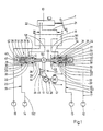
- Fig. 4 einen Längsschnitt eines Bremsdruckstellers in den Anfahrhilfe-Vorrichtungen in Fig. 1 - 3 gemäß einem bevorzugten Ausführungsbeispiel,
- Fig. 5 eine vormontierte Baugruppe des Bremsdruckstellers in Fig. 4.
- 1 a section of a schematic diagram of a hydraulic brake device for a car with a starting aid device,
- 2 and 3 each show a longitudinal section of a traction help device according to two further exemplary embodiments,
- 4 shows a longitudinal section of a brake pressure adjuster in the traction help devices in FIGS. 1-3 according to a preferred exemplary embodiment,
- 5 shows a preassembled assembly of the brake pressure actuator in FIG. 4.
Von der in Fig. 1 auschnittweise und schematisch abgebildeten hydraulischen Bremseinrichtung für ein Personenkraftfahrzeug (PKW) sind lediglich ein Hauptbremszylinder 10, der von einem Bremspedal 11 mechanisch betätigt wird, und die Radbremszylinder 12 - 15 für die Fahrzeugräder dargestellt. Jeweils zwei Radbremszylinder 12,13 bzw. 14,15 sind in zwei unabhängigen Bremskreisen I bzw. II angeordnet, wobei die Radbremszylinder 13,14 den Antriebsrädern, hier den Hinterrädern, zugeordnet sind. Die Bremseinrichtung ist üblicherweise noch mit einem Antiblockiersystem (ABS) 16 ausgerüstet, das in die Bremskreise I und II zwischen Hauptbremszylinder 10 und den Radbremszylindern 12 - 15 eingeschaltet ist. Dabei ist jeder Radbremszylinder 12 - 15 über eine separate Bremsleitung mit dem Antiblockiersystem 16 verbunden, das über je eine Druckleitung 21 bzw. 22 pro Bremskreis I bzw. II an dem Hauptbremszylinder 16 angeschlossen ist.1, only a
In den Bremsleitungen 18,19 zu den Radbremszylindern 13,14 der Antriebsräder ist die eine Anfahrhilfe darstellende Vorrichtung zum Synchronisieren der Drehzahl der Antriebsräder beim Anfahren, im folgenden kurz Anfahrhilfe-Vorrichtung 23 genannt, eingeschaltet. Sie besteht aus zwei Bremsdruckstellern 24,25 und aus einem Stellglied 26 zum Betätigen der Bremsdrucksteller 24,25 in Abhängigkeit von der Drehzahldifferenz der Antriebsräder beim Anfahren. Wie nicht besonders dargestellt ist, wird die Drehzahl der Antriebsräder durch Radsensoren erfaßt, die ohnehin für das Antiblockiersystem 16 erforderlich sind. Die beiden Bremsdrucksteller 24,25 sind identisch ausgebildet und axial fluchtend zueinander ausgerichtet. Jeder Bremsdrucksteller 24 bzw. 25 weist einen Steuerzylinder 27 auf, in welchem ein Steuerkolben 28 axial verschieblich angeordnet ist. Der Steuerkolben 28 begrenzt einen Steuerraum 29, der eine Anschlußöffnung 30 zum Anschließen des zum Radbremszylinder 13 bzw. 14 des Antriebsrades führenden Bremsleitungsabschnittes 182 bzw. 192 aufweist. Der Steuerkolben 28 trägt eine Ringnut 31, die über eine Querbohrung 32 mit einer im Steuerraum 29 mündenden Axialbohrung 33 im Steuerkolben 28 in Verbindung steht. Die Ringnut 31 überdeckt in jeder Stellung des Steuerkolbens 28 eine Anschlußöffnung 34, an welcher der zu dem Antiblockiersystem 16 führende Abschnitt 181 bzw. 191 der Bremsleitung 18 bzw. 19 angeschlossen ist. Beidseitig der Ringnut 31 ist der Steuerkolben 28 gegenüber dem Steuerzylinder 27 durch Dichtungsmanschetten 35 bzw. 36 abgedichtet. Der Steuerkolben 28 wird durch eine im Steuerraum 29 angeordnete Rückstellfeder 37, die sich einerseits an dem Steuerkolben 28 und andererseits an einem Anschlag 38 in dem Steuerraum 29 abstützt, in seiner Grundstellung gehalten. Die Öffnung der Axialbohrung 33 im Steuerkolben 28 ist von einem Ventilsitz 39 umgeben, der mit einem Ventilglied 41 eines Ventils 40 zusammenwirkt. Das Ventilglied 41 liegt mit Abstand vor dem Ventilsitz 39 unter der Wirkung einer Ventilfeder 42 an einem Anschlag 43 an. Bei Verschiebung des Steuerkolbens 28 setzt sich der Ventilsitz 39 auf das Ventilglied 41 unter Abdichtung der stirnseitigen Mündung der Axialbohrung 33 auf und verschiebt entgegen der Wirkung der Ventilfeder 42 bei geschlossenem Ventil 40 das Ventilglied 41. Der Steuerkolben 28 ragt mit einem einstückigen Antriebsbolzen 44 aus dem Steuerzylinder 27 des Bremsdruckstellers 24 bzw. 25 heraus.In the
Das Stellglied 26 ist als elektrischer Stellmotor 46, und zwar als Rotationsmotor, ausgebildet, dessen Rotorwelle 47 über ein die Drehbewegung der Rotorwelle 47 in eine Linearbewegung umsetzendes Umsetzgetriebe 48 jeweils einen der beiden Antriebsbolzen 44 der Bremsdrucksteller 24,25 betätigt. Das Umsetzgetriebe 48 weist hierzu einen zweiarmigen Hebel 49 auf, an dessen einem Hebelende eine Rolle 50 und an dessen anderem Hebelende ein Zahnsegment 51 angeordnet ist. Das Zahnsegment 51 kämmt mit einem mit der Rotorwelle 47 umlaufenden Zahnrad 52, während an der Rolle 50 auf diametral gegenüberliegenden Seiten die Antriebsbolzen 44 der Steuerkolben 28 der beiden Bremsdrucksteller 24,25 unter der Wirkung der Rückstellfedern 37 anliegen.The
Die Wirkungsweise der Anfahrhilfe-Vorrichtung 23 ist wie folgt:The
Im inaktiven Zustand der Anfahrhilfe-Vorrichtung 23 sind die Ventile 40 in den beiden Bremsdruckstellern 24,25 geöffnet, so daß die beiden Bremsleitungen 18,19 zwischen dem Antiblockiersystem 16 und den Radbremszylindern 13,14 der Antriebsräder durchgängig sind und ein evtl. durch Betätigen des Bremspedals 11 über den Hauptbremszylinder 10 eingesteuerte Bremsdruck an die Radbremszylinder 13,14 gelangt. Dreht beim Anfahren eines der beiden Antriebsräder 13,14 infolge schlechterer Bodenhaftung schneller als das andere, so wird aus den von den Radsensoren an eine nicht dargestellte Steuervorrichtung gelieferten Drehzahlsignalen ein der Drehzahldifferenz proportionales Stellsignal generiert, das an den Stellmotor 46 gelangt. Die Rotorwelle 47 wird entsprechend diesem Stellsignal verdreht, wobei das mit dem Zahnsegment 51 kämmende Zahnrad 52 den Hebel 49 je nach Drehrichtung der Rotorwelle 47 nach links oder rechts verschwenkt. Weist das dem Radbremszylinder 13 zugeordnete Antriebsrad die höhere Drehzahl auf, so wird der Hebel 49 nach rechts verschwenkt. Dadurch wird über die Rolle 50 der Steuerkolben 28 des Bremsdruckstellers 24 nach rechts verschoben. Nach einem geringen Verschiebeweg setzt sich der Ventilsitz 39 auf das Ventilglied 41 auf, und die Bremsleitung 18 wird aufgetrennt, wobei die Verbindung des Steuerraums 29 zu dem Bremsleitungsabschnitt 181 abgedichtet ist. Mit der weiteren Verschiebung des Steuerkolbens 28 wird das Volumen des Steuerraums 29 bei geschlossen gehaltenem Ventil 40 weiter reduziert und dadurch ein Bremsdruck über den Bremsleitungsabschnitt 182 in den Radbremszylinder 13 eingesteuert. Der Steuerkolben 28 wird dabei solange verschoben, bis der in den Radbremszylinder 13 eingesteuerte Bremsdruck die Drehzahldifferenz zwischen den Antriebsrädern zu Null werden läßt. Nach dem Anfahrvorgang geht der Steuerkolben 28 unter der Wirkung seiner Rückstellfeder 37 wieder in die Fig. 1 dargestellte Grundstellung zurück. Der gleiche Vorgang spielt sich in dem Bremsdrucksteller 25 ab, wenn das dem Radbremszylinder 14 zugeordnete Antriebsrad beim Anfahren mit einer gegenüber dem anderen Antriebsrad 13 größeren Drehzahl dreht.In the inactive state of the
Die in Fig. 2 schematisch dargestellte Anfahrhilfe-Vorrichtung 223 stimmt weitgehend mit der in Fig. 1 dargestellten überein, so daß gleiche Bauteile mit gleichen Bezugszeichen versehen sind. Während die Bremsdrucksteller 24,25 und der Stellmotor 46 mit Rotorwelle 47 und Zahnrad 52 identisch wie in Fig. 1 ausgebildet sind, ist das Umsetzgetriebe 248 modifiziert. Es weist eine Zahnstange 253 auf, die axial verschieblich geführt ist und mit dem Zahnrad 52 in Eingriff steht. An jeder Stirnseite der Zahnstange 253 liegt ein Steuerkolben 28 der beiden Bremsdrucksteller 24,25 unter der Andruckkraft der jeweiligen Rückstellfeder 37 an. Beim Drehen des Stellmotors 46 verschiebt das drehende Zahnrad 52 die Zahnstange 253 entsprechend der Drehrichtung des Stellmotors 46 nach links oder rechts und verschiebt in gleicher Weise wie vorstehend beschrieben einen der beiden Steuerkolben 28.The
Bei dem Ausführungsbeispiel der Anfahrhilfe-Vorrichtung 323 in Fig. 3 sind die beiden identisch und wie in Fig. 1 ausgebildeten Bremsdrucksteller 24,25 parallel und im Abstand voneinander angeordnet. Das Umsetzgetriebe 348 weist wiederum einen zweiarmigen Hebel 349 auf, der genau mittig zwischen den beiden Bremsdruckstellern 24,25 um einen ortsfesten Drehpunkt 354 gelagert ist. Der Hebel 349 trägt an jedem Hebelende eine Rolle 350 und eine Rolle 350*, an denen jeweils ein Steuerkolben 28 der beiden Bremdrucksteller 24,25 über ihre Antriebsbolzen 44 unter der Wirkung ihrer Rückstellfedern 37 anliegen. Im Bereich seines Drehpunktes 354 trägt der Hebel 349 ein Zahnsegment 351, das wiederum mit dem auf der Rotorwelle 47 des Stellmotors 46 drehfest sitzenden Zahnrad 52 kämmt. Dreht sich die Rotorwelle 47 infolge eines an den Stellmotor 46 gelangenden Stellsignals um einen bestimmten Drehwinkel, so wird der Hebel 349 verschwenkt und verschiebt einen Steuerkolben 28 der beiden Bremsdrucksteller 24,25, wobei in gleicher Weise wie zu Fig. 1 beschrieben ein Bremsdruck in denjenigen Radbremszylinder 13 bzw. 14 eingesteuert wird, dessen zugeordnetes Antriebsrad die höhere Drehzahl aufweist.In the exemplary embodiment of the
Eine bevorzugte Ausführungsform eines Bremsdruckstellers, wie er als Bremsdrucksteller 24 oder 25 in den Anfahrhilfe-Vorrichtungen 23,223 oder 323 in Fig. 1 - 3 eingesetzt werden kann, ist in Fig. 4 im Längsschnitt dargestellt. Der Steuerzylinder 27 weist zwei verschieden lange Zylinderabschnitte 271 und 272 auf. Im längeren ersten Zylinderabschnitt 271 ist der Steuerkolben 28 axial verschieblich geführt, wobei er durch eine Ringmanschette 55 gegenüber der inneren Zylinderwand des ersten Zylinderabschnittes 271 abgedichtet ist. Im zweiten Zylinderabschnitt 272, dessen lichter Durchmesser gegenüber dem des ersten Zylinderabschnittes 271 reduziert ist, ist das Ventil 40 angeordnet. In dem zweiten Zylinderabschnitt 272, der zusammen mit einem veränderlichen Teil des ersten Zylinderabschnittes 271 den von der Stirnfläche des Steuerkolbens 28 begrenzten Steuerraum 29 des Bremsdruckstellers bildet, ist die Anschlußöffnung 30 zum Anschließen des hier zum Radbremszylinder 14 führenden Bremsleitungsabschnittes 192 radial und die Anschlußöffnung 34 zum Anschließen des zum Hauptzylinder 10 bzw. zu dem Antiblockiersystem 16 führenden Bremsleitungsabschnittes 191 axial eingebracht. Der Ventilsitz 39 umgibt die Anschlußöffnung 34, auf dem sich der Schließkopf 56 des wiederum axial verschieblichen Ventilgliedes 41 aufsetzen kann. Das Ventilglied 41 weist einen über den Schließkopf 56 radial überstehenden Führungsflansch 57 auf, der zur Führung des Ventilgliedes 41 in dem zweiten Zylinderabschnitt 272 dient. Das Ventilglied 41 weist einen Schaft 58 auf, der den ersten Zylinderabschnitt 271 vom Steuerkolben 28 an durchzieht und in dem zweiten Zylinderabschnitt 272 stirnseitig mit einem Tragbund 59 endet. Auf den Tragbund 59 ist ein den Schließkopf 56 bildendes Gummiteil 60 mit stirnseitiger Dichtlippe 61 aufgeschnappt, das den Tragbund 59 hintergreift. Bei geschlossenem Ventil 40 wird die Dichtlippe 61 auf den Ventilsitz 39 aufgepreßt und damit die Anschlußöffnung 34 abgedichtet. Um ein ungewolltes Abziehen des Gummiteils 60 zu verhindern, ist dieses mittels einer Metallarmierung 62 auf dem Tragbund 59 gesichert. Das Gummiteil 60 ist konisch ausgebildet und verjüngt sich zum Ventilsitz 39 hin. Der Flankenwinkel des Konus beträgt etwa 5 - 10°. Das Gummiteil 60 hintergreift den Tragbund 59 und die Metallarmierung 62 hintergreift das Gummiteil 60. Bei entsprechender Ausbildung der jeweiligen Übergreifungsränder wird ein Abziehen des Gummiteils 60 bei Öffnen des Ventils 40 oder bei einem in die Radbremszylinder 13,14 eingesteuerten Bremsdruck sicher vermieden.A preferred embodiment of a brake pressure adjuster, as can be used as
Die Rückstellfeder 37 für den Stellkolben 28 stützt sich an zwei das Ventilglied 41, und zwar den Schaft 58, koaxial umschließenden Federtellern 63 und 64 ab. Der eine Federteller 63 liegt dabei an der ringförmigen Übergangsschulter 65 zwischen dem ersten Zylinderabschnitt 271 und dem zweiten Zylinderabschnitt 272 an. Sein lichter Innendurchmesser ist kleiner gewählt als der Außendurchmesser des Führungsflansches 57. Der andere Federteller 64 ist axial verschieblich auf dem Schaft 58 des Ventilgliedes 41 angeordnet und an dem vom Schließkopf 56 abgkehrten Ende des Schaftes 58 an einen Anschlag 66 unter der Wirkung der Rückstellfeder 37 anlegbar. Die Ventilfeder 42 stützt sich einerseits an dem Federteller 64 und andererseits an dem Schaft 58 des Ventilgliedes 41 an. Der Steuerkolben 28 trägt auf seiner den Steuerraum 29 begrenzenden Stirnfläche eine Abstützfläche 67 für den Federteller 64. Der Steuerkolben 28 weist außerdem noch eine zentrale, axial verlaufende Sackbohrung 68 auf, die in der den Steuerraum 29 begrenzenden Stirnfläche des Steuerkolbens 28 mündet. Die Sackbohrung 68 hat eine solche Tiefe, daß bei maximalem Verschiebeweg des Steuerkolbens 28 ein Teilabschnitt des Schaftes 58 des Ventilgliedes 41 ohne Behinderung der Verschiebebewegung des Steuerkolbens 28 in die Sackbohrung 68 eintauchen kann.The
Durch das Vorsehen der beiden Federteller 63,64 und deren konstruktive Ausbildung und Anordnung auf dem Ventilglied 41 ist es möglich, das Ventilglied 41 zusammen mit der Rückstellfeder 37 und der Ventilfeder 42 als komplette Baugruppe 70 vorzumontieren. Diese Baugruppe 70 ist in Fig. 5 dargestellt. Wie dort zu sehen ist, liegt der Federteller 63 unter der Druckkraft der Rückstellfeder 37 an dem Führungsflansch 47 an, während der Federteller 64 gegen den Anschlag 66 gelegt wird. Diese vormontierte Baugruppe 70 wird bei der Montage des Bremsdruckstellers in den Steuerzylinder 27, in Fig. 4 von rechts her, eingeschoben, bis der Schließkopf 56 des Ventilgliedes 41 zusammen mit dem Führungsflansch 57 in den zweiten Zylinderabschnitt 272 eintaucht und der Federteller 63 sich an der Übergangsschulter 65 zwischen den Zylinderabschnitten 271 und 272 abstützt. Danach wird der Steuerkolben 28 mit seiner Dichtmanschette 55 eingeschoben und schließlich der Steuerzylinder 27 mit einem Abschlußstück 69 verschlossen. Das Abschlußstück 69 wird durch einen Sicherungsring 71 gehalten, der in eine Ausnehmung 72 in der Zylinderwand eingelegt ist. Das Abschlußstück 69 weist eine zentrale Führungsbohrung 73 auf, in welcher der Antriebsbolzen 44 für den Steuerkolben 28 axial verschieblich geführt ist. Der Antriebsbolzen 44 ist hier als vom Steuerkolben 28 getrenntes separates Bauteil ausgebildet, das an dem Steuerkolben 28 unter der Wirkung des an ihm angreifenden Stellgliedes 26 (in Fig.4 nicht dargestellt) anliegt. Durch die Zweiteiligkeit von Steuerkolben 28 und Antriebsbolzen 44 wird verhindert, daß Querkräfte auf die Kolbenlauffläche eingeleitet werden und zu einer Schwergängigkeit des Steuerkolbens 28 führen.By providing the two
Die Wirkungsweise dieses Bremsdruckstellers ist die gleiche, wie zu Fig. 1 beschrieben. Durch Verschieben des Steuerkolbens 28 über den vom Stellglied 26 betätigten Antriebskolben 44 wird zunächst das Ventilglied 41 so weit verschoben, bis die Dichtlippe 61 des Schließkopfes 56 auf dem Ventilsitz 39 aufliegt. Bei der weiteren Verschiebebewegung des Steuerkolbens 28 entgegen seiner Rückstellfeder 37 wird dann die Ventilfeder 42 zusammengepreßt, die dadurch zunehmenden Schließdruck auf den Schließkopf 56 ausübt. Da nunmehr der Bremsleitungsabschnitt 191 abgeschlossen ist und der Steuerraum 29, der Bremsleitungsabschnitt 192 und der Radbremszylinder 14 mit Bremsflüssigkeit gefüllt sind, wird mit der Reduzierung des Steuerraumvolumens durch die Verschiebebewegung des Steuerkolbens 28 ein Bremsdruck in den zugeordneten Radbremszylinder 14 eingesteuert, der entsprechend der Drehzahldifferenz zwischen den Antriebsrädern dosiert ist.The operation of this brake pressure actuator is the same as that described for FIG. 1. By displacing the
Die Erfindung ist nicht auf die vorstehend beschriebenen Ausführungsbeispiele beschränkt. So kann in Abwandlung der Fig.2 das Stellglied 26 auch als Linearmotor ausgebildet werden, dessen Läufer von der Zahnstange 253 gebildet wird. Auch ist ein Antiblockiersystem nicht notwendiger Bestandteil der Bremseinrichtung. Fehlt dieses, so sind die Druckleitungen unmittelbar an dem Hauptbremszylinder angeschlossen. Für die Antriebsräder sind separate Drehzahlsensoren vorzusehen.The invention is not restricted to the exemplary embodiments described above. 2, the
Claims (9)
Priority Applications (1)
| Application Number | Priority Date | Filing Date | Title |
|---|---|---|---|
| AT88101746T ATE56921T1 (en) | 1987-03-05 | 1988-02-06 | DEVICE FOR SYNCHRONIZING THE SPEED OF DRIVE WHEELS OF A VEHICLE WHEN STARTING. |
Applications Claiming Priority (2)
| Application Number | Priority Date | Filing Date | Title |
|---|---|---|---|
| DE19873707068 DE3707068A1 (en) | 1987-03-05 | 1987-03-05 | DEVICE FOR SYNCHRONIZING THE SPEED OF DRIVE WHEELS OF A VEHICLE WHEN STARTING UP |
| DE3707068 | 1987-03-05 |
Publications (2)
| Publication Number | Publication Date |
|---|---|
| EP0285763A1 true EP0285763A1 (en) | 1988-10-12 |
| EP0285763B1 EP0285763B1 (en) | 1990-09-26 |
Family
ID=6322338
Family Applications (1)
| Application Number | Title | Priority Date | Filing Date |
|---|---|---|---|
| EP88101746A Expired - Lifetime EP0285763B1 (en) | 1987-03-05 | 1988-02-06 | Device for synchronizing the speeds of the driving wheels of a vehicle during acceleration |
Country Status (5)
| Country | Link |
|---|---|
| US (1) | US4805965A (en) |
| EP (1) | EP0285763B1 (en) |
| JP (1) | JPS63232058A (en) |
| AT (1) | ATE56921T1 (en) |
| DE (2) | DE3707068A1 (en) |
Cited By (2)
| Publication number | Priority date | Publication date | Assignee | Title |
|---|---|---|---|---|
| EP0395262A2 (en) * | 1989-04-22 | 1990-10-31 | LUCAS INDUSTRIES public limited company | Brake actuator |
| WO1991012161A1 (en) * | 1990-02-10 | 1991-08-22 | Robert Bosch Gmbh | Hydraulic dual-circuit brake system |
Families Citing this family (11)
| Publication number | Priority date | Publication date | Assignee | Title |
|---|---|---|---|---|
| JP2548747B2 (en) * | 1987-10-19 | 1996-10-30 | アイシン精機株式会社 | Hydraulic brake device |
| DE3839178A1 (en) * | 1988-01-26 | 1989-08-03 | Daimler Benz Ag | ANTI-BLOCKING SYSTEM |
| DE3808902C2 (en) * | 1988-03-17 | 1996-04-11 | Teves Gmbh Alfred | Hydraulic, slip-controlled vehicle brake system |
| DE3816073C2 (en) * | 1988-05-11 | 1997-04-24 | Bosch Gmbh Robert | Anti-lock and traction control system |
| DE3819812A1 (en) * | 1988-06-10 | 1989-12-21 | Bosch Gmbh Robert | ANTI-BLOCKING CONTROL SYSTEM |
| JPH0245249A (en) * | 1988-08-04 | 1990-02-15 | Akebono Brake Res & Dev Center Ltd | Brake hydraulic pressure control device for vehicle |
| DE3928109A1 (en) * | 1989-08-25 | 1991-02-28 | Bosch Gmbh Robert | ELECTRICALLY DRIVABLE PRINTER FOR A HYDRAULIC VEHICLE BRAKE SYSTEM |
| DE4112141A1 (en) * | 1991-04-13 | 1992-10-15 | Bosch Gmbh Robert | DRIVE CONTROL SYSTEM |
| US5163744A (en) * | 1991-10-21 | 1992-11-17 | General Motors Corporation | Combined traction control and anti-lock braking system |
| JP3539585B2 (en) * | 1995-01-13 | 2004-07-07 | 株式会社ボッシュオートモーティブシステム | Brake system with automatic braking device |
| US7798577B2 (en) * | 2007-02-13 | 2010-09-21 | Bond James R | Apparatus including a brake control assembly having a brake fluid accumulator assembly |
Citations (4)
| Publication number | Priority date | Publication date | Assignee | Title |
|---|---|---|---|---|
| DE3127301C2 (en) * | 1981-07-10 | 1983-08-04 | Daimler-Benz Ag, 7000 Stuttgart | "Propulsion control device for a vehicle that is also equipped with an anti-lock braking system. |
| GB2119883A (en) * | 1982-04-28 | 1983-11-23 | Bosch Gmbh Robert | Anti-skid anti-spin regulation for vehicle wheels |
| GB2128278A (en) * | 1982-10-01 | 1984-04-26 | Kugelfischer G Schaefer & Co | Anti-wheelspin brake control for wheels driven via a differential gear |
| DE3534443C1 (en) * | 1985-09-27 | 1986-11-13 | Daimler-Benz Ag, 7000 Stuttgart | Propulsion control device for a motor vehicle |
Family Cites Families (10)
| Publication number | Priority date | Publication date | Assignee | Title |
|---|---|---|---|---|
| US3420580A (en) * | 1967-05-11 | 1969-01-07 | Trw Inc | Skid control device |
| US3893535A (en) * | 1968-11-02 | 1975-07-08 | Daimler Benz Ag | Installation for preventing spinning of the driven wheels of a motor vehicle |
| US3952511A (en) * | 1974-12-30 | 1976-04-27 | Allis-Chalmers Corporation | Hydrostatic drive circuit |
| US4082369A (en) * | 1976-08-02 | 1978-04-04 | Black Richard D | Anti-skid and pressure balanced hydraulic brake system |
| US4206950A (en) * | 1978-04-17 | 1980-06-10 | The Bendix Corporation | Anti-skid and anti-spin brake system |
| US4236595A (en) * | 1979-08-17 | 1980-12-02 | Parno Corp. | Auxiliary drive system |
| US4401182A (en) * | 1980-12-10 | 1983-08-30 | Sundstrand Corporation | Variable displacement hydraulic drive with disconnect |
| EP0128583B1 (en) * | 1983-06-14 | 1988-12-14 | Robert Bosch Gmbh | Four-wheel drive vehicle |
| US4575161A (en) * | 1984-08-10 | 1986-03-11 | Vanzant Teddy L | Anti-spin device |
| US4653815A (en) * | 1985-10-21 | 1987-03-31 | General Motors Corporation | Actuating mechanism in a vehicle wheel brake and anti-lock brake control system |
-
1987
- 1987-03-05 DE DE19873707068 patent/DE3707068A1/en not_active Withdrawn
-
1988
- 1988-02-06 AT AT88101746T patent/ATE56921T1/en not_active IP Right Cessation
- 1988-02-06 EP EP88101746A patent/EP0285763B1/en not_active Expired - Lifetime
- 1988-02-06 DE DE8888101746T patent/DE3860679D1/en not_active Expired - Lifetime
- 1988-03-03 US US07/163,674 patent/US4805965A/en not_active Expired - Fee Related
- 1988-03-04 JP JP63049946A patent/JPS63232058A/en active Pending
Patent Citations (4)
| Publication number | Priority date | Publication date | Assignee | Title |
|---|---|---|---|---|
| DE3127301C2 (en) * | 1981-07-10 | 1983-08-04 | Daimler-Benz Ag, 7000 Stuttgart | "Propulsion control device for a vehicle that is also equipped with an anti-lock braking system. |
| GB2119883A (en) * | 1982-04-28 | 1983-11-23 | Bosch Gmbh Robert | Anti-skid anti-spin regulation for vehicle wheels |
| GB2128278A (en) * | 1982-10-01 | 1984-04-26 | Kugelfischer G Schaefer & Co | Anti-wheelspin brake control for wheels driven via a differential gear |
| DE3534443C1 (en) * | 1985-09-27 | 1986-11-13 | Daimler-Benz Ag, 7000 Stuttgart | Propulsion control device for a motor vehicle |
Cited By (3)
| Publication number | Priority date | Publication date | Assignee | Title |
|---|---|---|---|---|
| EP0395262A2 (en) * | 1989-04-22 | 1990-10-31 | LUCAS INDUSTRIES public limited company | Brake actuator |
| EP0395262A3 (en) * | 1989-04-22 | 1991-07-17 | LUCAS INDUSTRIES public limited company | Brake actuator |
| WO1991012161A1 (en) * | 1990-02-10 | 1991-08-22 | Robert Bosch Gmbh | Hydraulic dual-circuit brake system |
Also Published As
| Publication number | Publication date |
|---|---|
| DE3860679D1 (en) | 1990-10-31 |
| EP0285763B1 (en) | 1990-09-26 |
| US4805965A (en) | 1989-02-21 |
| DE3707068A1 (en) | 1988-09-15 |
| ATE56921T1 (en) | 1990-10-15 |
| JPS63232058A (en) | 1988-09-28 |
Similar Documents
| Publication | Publication Date | Title |
|---|---|---|
| DE3920766C2 (en) | Vacuum brake booster for a slip-controlled brake system | |
| EP1001143B1 (en) | Valve control for intake and exhaust valves in internal combustion engines | |
| EP0292648B1 (en) | Brake installation with antilock and/or driving slip control as well as brake pressure modulator for such brake installation | |
| EP0285763B1 (en) | Device for synchronizing the speeds of the driving wheels of a vehicle during acceleration | |
| EP0435113A1 (en) | Vehicle brake installation | |
| DE19700979A1 (en) | magnetic valve | |
| EP0845397A2 (en) | Pressure control device for electro-pneumatic vehicle braking systems, especially commercial vehicles | |
| DE3631128C2 (en) | ||
| DE2127187C3 (en) | Control device for a hydraulic power steering | |
| WO2018069010A1 (en) | Solenoid valve and hydraulic braking system for a vehicle | |
| EP0607370B2 (en) | Piston with central valve for hydraulic braking systems | |
| EP0323972B1 (en) | Rotary gate valve for hydraulic servo-assisted steering systems | |
| EP0726857A1 (en) | Pneumatic brake servo | |
| DE2824352A1 (en) | ANTI-LOCK BRAKING SYSTEM FOR A VEHICLE BRAKING SYSTEM | |
| WO1993011010A1 (en) | Actuating unit for a hydraulic braking system | |
| DE4226714A1 (en) | BRAKE CONTROL DEVICE | |
| DE4202595C2 (en) | Controlled dependent on the external signal, pressure differential actuated compensating differential of a motor vehicle | |
| DE4134421C2 (en) | Controlled dependent on the external signal, pressure differential actuated compensating differential of a motor vehicle | |
| DE4410769C2 (en) | Valve assembly for controlling a vacuum brake booster with an electromagnetic actuator | |
| DE3904614C2 (en) | Pressure modulator based on the plunger principle for a hydraulic motor vehicle brake system with anti-lock control device | |
| WO1990011217A1 (en) | Electro-hydraulic steering assister for motor vehicles | |
| DE3717237C2 (en) | Brake system with anti-lock and / or traction control | |
| EP0413950A1 (en) | Pressure source for a hydraulic vehicle brake system | |
| EP0701076A1 (en) | Electromagnetic valve | |
| DE2548992C3 (en) | Dual-line compressed air brake system for vehicles with trailers, with a trailer control valve and a shut-off valve |
Legal Events
| Date | Code | Title | Description |
|---|---|---|---|
| PUAI | Public reference made under article 153(3) epc to a published international application that has entered the european phase |
Free format text: ORIGINAL CODE: 0009012 |
|
| AK | Designated contracting states |
Kind code of ref document: A1 Designated state(s): AT DE FR GB SE |
|
| 17P | Request for examination filed |
Effective date: 19890304 |
|
| 17Q | First examination report despatched |
Effective date: 19900316 |
|
| GRAA | (expected) grant |
Free format text: ORIGINAL CODE: 0009210 |
|
| AK | Designated contracting states |
Kind code of ref document: B1 Designated state(s): AT DE FR GB SE |
|
| REF | Corresponds to: |
Ref document number: 56921 Country of ref document: AT Date of ref document: 19901015 Kind code of ref document: T |
|
| ET | Fr: translation filed | ||
| REF | Corresponds to: |
Ref document number: 3860679 Country of ref document: DE Date of ref document: 19901031 |
|
| GBT | Gb: translation of ep patent filed (gb section 77(6)(a)/1977) | ||
| PGFP | Annual fee paid to national office [announced via postgrant information from national office to epo] |
Ref country code: SE Payment date: 19910207 Year of fee payment: 4 |
|
| PGFP | Annual fee paid to national office [announced via postgrant information from national office to epo] |
Ref country code: AT Payment date: 19910226 Year of fee payment: 4 |
|
| PGFP | Annual fee paid to national office [announced via postgrant information from national office to epo] |
Ref country code: FR Payment date: 19910227 Year of fee payment: 4 |
|
| PGFP | Annual fee paid to national office [announced via postgrant information from national office to epo] |
Ref country code: DE Payment date: 19910429 Year of fee payment: 4 |
|
| PLBE | No opposition filed within time limit |
Free format text: ORIGINAL CODE: 0009261 |
|
| STAA | Information on the status of an ep patent application or granted ep patent |
Free format text: STATUS: NO OPPOSITION FILED WITHIN TIME LIMIT |
|
| 26N | No opposition filed | ||
| PG25 | Lapsed in a contracting state [announced via postgrant information from national office to epo] |
Ref country code: GB Effective date: 19920206 Ref country code: AT Effective date: 19920206 |
|
| PG25 | Lapsed in a contracting state [announced via postgrant information from national office to epo] |
Ref country code: SE Effective date: 19920207 |
|
| GBPC | Gb: european patent ceased through non-payment of renewal fee | ||
| PG25 | Lapsed in a contracting state [announced via postgrant information from national office to epo] |
Ref country code: FR Effective date: 19921030 |
|
| PG25 | Lapsed in a contracting state [announced via postgrant information from national office to epo] |
Ref country code: DE Effective date: 19921103 |
|
| REG | Reference to a national code |
Ref country code: FR Ref legal event code: ST |
|
| EUG | Se: european patent has lapsed |
Ref document number: 88101746.1 Effective date: 19920904 |