EP0285664B1 - Apparatus for detecting metal mold touch position in an electrically powered straight-acting mold-clamping mechanism - Google Patents
Apparatus for detecting metal mold touch position in an electrically powered straight-acting mold-clamping mechanism Download PDFInfo
- Publication number
- EP0285664B1 EP0285664B1 EP87906105A EP87906105A EP0285664B1 EP 0285664 B1 EP0285664 B1 EP 0285664B1 EP 87906105 A EP87906105 A EP 87906105A EP 87906105 A EP87906105 A EP 87906105A EP 0285664 B1 EP0285664 B1 EP 0285664B1
- Authority
- EP
- European Patent Office
- Prior art keywords
- touch position
- die
- servo
- circuit
- servomotor
- Prior art date
- Legal status (The legal status is an assumption and is not a legal conclusion. Google has not performed a legal analysis and makes no representation as to the accuracy of the status listed.)
- Expired
Links
Images


Classifications
-
- B—PERFORMING OPERATIONS; TRANSPORTING
- B29—WORKING OF PLASTICS; WORKING OF SUBSTANCES IN A PLASTIC STATE IN GENERAL
- B29C—SHAPING OR JOINING OF PLASTICS; SHAPING OF MATERIAL IN A PLASTIC STATE, NOT OTHERWISE PROVIDED FOR; AFTER-TREATMENT OF THE SHAPED PRODUCTS, e.g. REPAIRING
- B29C45/00—Injection moulding, i.e. forcing the required volume of moulding material through a nozzle into a closed mould; Apparatus therefor
- B29C45/17—Component parts, details or accessories; Auxiliary operations
- B29C45/76—Measuring, controlling or regulating
- B29C45/80—Measuring, controlling or regulating of relative position of mould parts
Landscapes
- Engineering & Computer Science (AREA)
- Manufacturing & Machinery (AREA)
- Mechanical Engineering (AREA)
- Moulds For Moulding Plastics Or The Like (AREA)
- Injection Moulding Of Plastics Or The Like (AREA)
Abstract
Description
- The present invention relates to a mold clamping mechanism of an injection-molding machine, and more particularly, to a detecting apparatus capable of automatically accurately detecting a die-touch position of a direct mold clamping mechanism which is driven by means of a servomotor.
- Conventionally known is a motor-operated direct mold clamping mechanism in which a movable platen disposed between a stationary platen and a rear platen is driven for mold clamping by means of a servomotor which is connected to the movable platen through a transmission mechanism. In the mold clamping apparatus of this type, a predetermined mold clamping force is produced by driving a movable die additionally for a predetermined distance in the direction for pressure contact, from a position where the movable die is in contact with a stationary die. Also, a mold opening end position, a die protection start position, etc. are settled on the basis of the die-touch position. In order to produce the predetermined mold clamping force and to perform a specified die opening/closing operation, therefore, the die-touch position must be detected and set accurately. Since the die-touch position varies depending on the thickness of the dies, moreover, it must be detected and set every time the die thickness is changed.
- Conventionally, in detecting the die-touch position, an operator visually determines whether or not the die-touch position is reached by the movable platen, and manually adjusts the location of a limit switch for die-touch position detection so that the limit switch is turned on when the movable platen reaches the die-touch position. In this case, it is difficult to accurately determine the arrival at the die-touch position. For example, a movable die position in which a mold clamping force of a certain size is already produced may be mistaken for the die-touch position. In consequence, the die-touch position cannot be detected and set accurately, so that satisfactory products cannot be manufactured. Moreover, the fine manual adjustment of the location of the limit switch is so troublesome that the efficiency is lowered.
- The object of the present invention is to provide a die-touch position detecting apparatus of a motor-operated direct mold clamping mechanism, capable of detecting a die-touch position automatically and accurately.
- In order to achieve the above object, according to the present invention, there is provided a die-touch position detecting apparatus used in a motor-operated direct mold clamping mechanism which has a movable platen movable relatively to a stationary platen, and a servomotor operatively coupled to the movable platen through a transmission mechanism and adapted to be driven by a servo-circuit.
- The die-touch position detecting apparatus comprises drive control means for executing pulse distribution to the servo-circuit in response to a die-touch position detecting operation command, thereby moving the movable platen toward the stationary platen, stop means for causing the drive control means to stop the pulse distribution to the servo-circuit when the amount of errors accumulated in an error register of the servo-circuit exceeds a predetermined value, and calculating means for calculating a die-touch position in accordance with the amount of pulse distribution to the servo-circuit and the amount of errors when the pulse distribution is stopped.
- According to the present invention, as described above, pulses are distributed to the servo-circuit until the amount of errors accumulated in the error register of the servo-circuit exceeds the predetermined value, after the die-touch position detecting operation command is delivered. When the pulse distribution is stopped, the die-touch position is calculated on the basis of the amount of pulse distribution and the error amount. Thus, the die-touch position can be detected automatically, and the location of a limit switch for die-touch position detection need not be adjusted, so that the production efficiency can be improved. Also, the die-touch position can be detected with high accuracy corresponding to the cycle of production of pulses used to drive the servomotor.
-
- Fig. 1 is a schematic view illustrating part of a motor-operated direct mold clamping mechanism to which the present invention is applied;
- Fig. 2 is a schematic view showing a die-touch position detecting apparatus according to an embodiment of the present invention; and
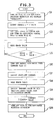
- Fig. 3 is a flow chart illustrating the operation of the apparatus of Fig. 2.
- In Fig. 1, a motor-operated direct mold clamping mechanism comprises a
stationary platen 100 and arear platen 102, which are fixed individually to a base (not shown) of an injection-molding machine, and amovable platen 101 disposed between theplatens movable platen 101 is connected to a drive source, composed of aservomotor 103, by means of transmission means 104 which includes a ball screw and a ball nut, for example.Dies platens movable platen 101 is driven further from a die-touch position P1, where the two dies are in contact with each other, toward thestationary platen 100, that is, in an advancing direction. Thedies platens - As shown in Fig. 2, a die-touch position detecting apparatus mounted on the injection-molding machine (not shown), which is provided with the aforementioned mold clamping mechanism, comprises a numerical control unit (hereinafter referred to as CNC) 10 with a built-in computer, a servo-
circuit 30 for driving the servomotor 103 (Fig. 1), and a pulse encoder P attached to theservomotor 103 and used to detect the rotational position of the motor, i.e., the moved position of themovable platen 101. Although theCNC 10 and the servo-circuit 30 are shown separately for ease of illustration, all the elements of the servo-circuit 30 except apower amplifier 36 are contained in theCNC 10. - The CNC 10 includes a microprocessor (hereinafter referred to as CPU) 11 for NC and a
CPU 12 for a programmable machine controller (hereinafter referred to as PMC). ThePMCCPU 12 is connected with aROM 13, which stores sequence programs and the like for executing die-touch position detecting operation and the like, while the NCCPU 11 is connected with a servo-interface 15 and aROM 14, which stores a control program for generally controlling the injection-molding machine. The servo-interface 15 is connected with various servo-circuits for controlling the drive of servomotors for various axes for injection, screw rotation, ejector operation, etc., besides theaforesaid servomotor 30. Having no relation to the present invention, however, illustration of these servo-circuits is omitted. - Numeral 16 denotes a nonvolatile common RAM which, having a backup power source, serves to store programs for controlling various operations of the injection-molding machine, and various set values, parameters, etc., which will be described later. Numeral 17 denotes a manual data input device with a CRT display (hereinafter referred to as CRT/MDI), which is connected to a bus-arbiter controller (hereinafter referred to as BAC) 19 through an
operator panel controller 18. TheBAC 19 is connected with the NCCPU 11, thePMCCPU 12, thecommon RAM 16, anoutput circuit 20, and aninput circuit 21, individually. Theoutput circuit 20 is connected to a D/A converter 38 of the servo-circuit 30.Numerals PMCCPU 12, respectively, and are used for tentative data storage. - In the servo-
circuit 30, anerror register 31 is supplied periodically with a movement command from the NCCPU 11 through the servo-interface 15. The movement command, which is indicative of a stroke for one period, is composed of a pulse train. As theservomotor 103 rotates, on the other hand, a pulse train is supplied from the pulse encoder P, and an error amount indicative of the difference between the two pulse trains is accumulated in theerror register 31. This error amount is converted into an analog voltage as a speed command value by a digital-to-analog converter (hereinafter referred to as D/A converter) 32. In order to improve the responsiveness of the servo-circuit, moreover, speed feedback operation is performed. More specifically, a voltage obtained by converting a signal from the encoder P by means of an F/V converter 37 and corresponding to an actual servomotor speed is subtracted from the aforesaid speed command value. The result of such subtraction, i.e., the difference between the command speed and the actual speed, is amplified by means of acompensator 33. By doing this, a voltage corresponding to the value of a current supplied to the armature of theservomotor 103, that is, a torque command, is obtained. Thereupon, atorque limit circuit 34 is provided which receives the the torque limit command and limits the output torque of the servomotor M. In order to improve the responsiveness to the output of thetorque limit circuit 34, acompensator 35 is used to amplify the difference between the torque command and a feedback voltage signal from acurrent detector 39, the feedback voltage signal corresponding to the armature current of theservomotor 103. Further, the output of thecompensator 35 is amplified by thepower amplifier 36, and then applied to theservomotor 103. Numeral 38 denotes the D/A converter which converts a torque limit command value from theCNC 10 into an analog signal, and applies the analog signal to thetorque limit circuit 34. - The error value of the
error register 31 can be read through the servo-interface 15 by means of the NCCPU 11. - Referring now to Fig. 3, the die-touch position detecting operation of the apparatus according to the present embodiment will be described.
- When an operator inputs the die-touch position detecting operation command through the CRT/
MDI 17 after attaching the dies to thestationary platen 100 and themovable platen 101, thePMCCPU 12 turns on a flag F1, indicative of the execution of the die-touch position detecting operation, in thecommon RAM 16, and makes an indication for the execution of the die-touch position detecting operation on a CRT screen of the CRT/MDI 17 (Step S1). Then, the PMCCPU 12 delivers a set torque limit value for the die-touch position detection to the D/A converter 38 of the servo-circuit 30 via theBAC 19 and the output circuit 20 (Step S2). The D/A converter 38 converts the specified torque limit value into an analog voltage signal, and applies it to thetorque limit circuit 34. As a result, thetorque limit circuit 34 operates so as to restrict the torque command to the torque limit value or below. Thus, theservomotor 103 is driven with a low torque not higher than this torque limit value. After delivering the torque limit value in this manner, thePMCCPU 12 sets a predetermined low feed speed for the die-touch position detection in thecommon RAM 16, and turns on a command flag F2 for continuous manual feed in the advancing direction, in the common RAM 16 (Step S3). On reading the activation of the continuous manual feed command flag F2, the NCCPU 11 performs pulse distribution corresponding to the predetermined feed speed, to the servo-circuit 30, and adds pulses to theerror register 31. The value in theerror register 31 is converted and delivered as the speed command value by the D/A converter 32, as mentioned before. The difference between the speed command value and the present actual speed from the F/V converter 37 is amplified by thecompensator 33, and is delivered as a torque command from thecompensator 33. Due to the torque limit operation, as mentioned before, thetorque limit circuit 34 never delivers such a torque command (voltage corresponding to the value of the current applied to the armature) as will permit production of a torque higher than a set value. The difference between the torque command and the actual armature current from thecurrent detector 39 is amplified by thecompensator 35, and theservomotor 103 is driven by means of thepower amplifier 36. Thus, themovable platen 101 is driven at low speed and with low torque. As theservomotor 103 rotates, on the other hand, a pulse train is applied from the pulse encoder P to theerror register 31. Every time one pulse is inputted, "1" is subtracted from the error value. As a result, the difference between the movement command from theCNC 10 and an actual stroke from the pulse encoder P is stored in theerror register 31. - While the
movable platen 10 is moving, theNCCPU 11 reads the error value from theerror register 31 through the servo-interface 15, and writes the value in a specified address of thecommon RAM 16 through theBAC 19. Then, thePMCCPU 12 reads the written error value (Step S4), and compares it with a set value (Step S5). The operations of Steps S4 and S5 are repeatedly executed while the movable platen is moving. - Thereafter, when the dies 105 and 106, attached to the
movable platen 101 and thestationary platen 100, respectively, engage each other, the movable platen ceases to advance, since the output torque of theservomotor 103 is restricted. As a result, feedback pulses from the pulse encoder P cease to be applied to theerror register 31, so that distributed pulses are accumulated in theerror register 31, thus increasing the error value above the set value. Thereupon, thePMCCPU 12 turns off the manual feed flag F2 in the common RAM (Step S6). In response to this, theNCCPU 11 stops continuous manual feed of a mold clamping axis. In other words, the pulse distribution to the servo-circuit 30 is stopped. Then, thePMCCPU 12 delivers a servo-off command to theNCCPU 11 through the common RAM 16 (Step S7), andNCCPU 11, on receiving the servo-off command, de-energizes theservomotor 103. Accordingly, theservomotor 103 is allowed to race, so that the dies 105 and 106 shift from a state such that they are pressed against each other with a force corresponding to the torque limit value, to a state such that they touch each other with a reaction force against the force of pressure contact. Thus, themovable platen 101 slightly retreats so that the pressure contact force goes out. As the platen retreats, the pulses delivered from the pulse encoder P are added to theerror register 31, so that the error value stored in theerror register 31 corresponds to the state that the dies 105 and 106 touch each other. Subsequently, thePMCCPU 12 reads the error value in the error register 31 (Step S8), while theNCCPU 11 subtracts the read error value from the amount of pulse distribution to theservomotor 103, thereby obtaining the present value of the position of the movable platen (Step S9). Then, the obtained present value is stored as the die-touch position in a die-touch position storage register TCHR (Step S10), the flag F1 for the execution of the die-touch position detecting operation is turned off, and the indication for the execution of the die-touch position detecting operation, on the CRT screen, is turned off (Step S11). Thus, the die-touch position detecting operation is finished. - If the set value used in Step S5 is made equal to a feed stop value of the
CNC 10, theNCCPU 11 automatically stops the pulse distribution when the error value attains the feed stop value. Thus, the set value may be adjusted to the feed stop value. - If the output torque of the servomotor can be made very small by the torque limit operation, the operation of Step S7 to de-energize the
servomotor 103 need not be performed. More specifically, the dies 105 and 106, in such a case, are pressed against each other with a very small force, so that there will not be any substantial difference if the die-touch position is obtained by subtracting the error value from the amount of pulse distribution immediately when the error value exceeds the set value.
Claims (4)
- A motor-operated direct mold clamping mechanism which has a movable platen movable relatively to a stationary platen, and a servomotor operatively coupled to said movable platen through a transmission mechanism and adapted to be driven by a servo-circuit, and a die-touch position detecting apparatus, comprising:
drive control means for executing pulse distribution to said servo-circuit in response to a die-touch position detecting operation command, thereby moving said movable platen toward said stationary platen;
stop means for causing said drive control means to stop the pulse distribution to said servo-circuit when the amount of errors accumulated in an error register of said servo-circuit exceeds a predetermined value; and
calculating means for calculating a die-touch position in accordance with the amount of pulse distribution to said servo-circuit and said amount of errors when the pulse distribution is stopped. - An apparatus according to claim 1, which further comprises torque limiting means for limiting the output torque of said servomotor, whereby said drive control means is caused to drive said movable platen with a small driving force.
- An apparatus according to claim 1 or 2, which further comprises manually operable command means for delivering said die-touch position detecting operation command.
- An apparatus according to claim 1 or 2, wherein said stop means delivers a control output when said amount of errors exceeds said predetermined value, said drive control means deenergizes said servomotor in response to said control output, and said calculating means calculates the die-touch position in response to said amount of pulse distribution and the amount of errors obtained after the deenergization of said servomotor.
Applications Claiming Priority (2)
| Application Number | Priority Date | Filing Date | Title |
|---|---|---|---|
| JP222103/86 | 1986-09-22 | ||
| JP61222103A JPH0661808B2 (en) | 1986-09-22 | 1986-09-22 | Die touch position detection method in electric direct pressure mold clamping mechanism |
Publications (3)
| Publication Number | Publication Date |
|---|---|
| EP0285664A1 EP0285664A1 (en) | 1988-10-12 |
| EP0285664A4 EP0285664A4 (en) | 1990-04-10 |
| EP0285664B1 true EP0285664B1 (en) | 1992-08-05 |
Family
ID=16777185
Family Applications (1)
| Application Number | Title | Priority Date | Filing Date |
|---|---|---|---|
| EP87906105A Expired EP0285664B1 (en) | 1986-09-22 | 1987-09-17 | Apparatus for detecting metal mold touch position in an electrically powered straight-acting mold-clamping mechanism |
Country Status (5)
| Country | Link |
|---|---|
| US (1) | US4846654A (en) |
| EP (1) | EP0285664B1 (en) |
| JP (1) | JPH0661808B2 (en) |
| DE (1) | DE3780947T2 (en) |
| WO (1) | WO1988001931A1 (en) |
Families Citing this family (12)
| Publication number | Priority date | Publication date | Assignee | Title |
|---|---|---|---|---|
| US5059365A (en) * | 1990-05-17 | 1991-10-22 | Cincinnati Milacron Inc. | Method of setting and maintaining a desired mold clamping force |
| EP0674985B1 (en) * | 1994-04-02 | 1999-08-11 | Karl Hehl | Mould closing unit for an injection moulding unit and method for its operation |
| GB2293568B (en) * | 1994-09-29 | 1998-04-22 | Nan Rong Mechanical Co Ltd | Tilting board device for matching with the linear displacement scale of an injection molding machine |
| US5582782A (en) * | 1995-03-01 | 1996-12-10 | Kato; Kazuo | Method of stopping a die of an injection molding machine and a die clamping apparatus |
| JP3002811B2 (en) * | 1995-10-20 | 2000-01-24 | 日精樹脂工業株式会社 | Control method and device for injection molding machine |
| US6011376A (en) * | 1998-03-13 | 2000-01-04 | Cincinnati Milacron Inc. | Method and apparatus for injection molding machine control |
| US5929583A (en) * | 1998-03-13 | 1999-07-27 | Cincinnati Milacron Inc. | Method and apparatus for detecting aberrant motor operation in a plastics processing machine |
| US6641757B2 (en) * | 2002-02-22 | 2003-11-04 | Industrial Technology Research Institute | Servo-driven type mold clamping unit mold protection method |
| DE10211640B4 (en) | 2002-03-15 | 2005-03-24 | Carl Freudenberg Kg | Torsionally flexible coupling |
| US6804836B2 (en) * | 2002-05-20 | 2004-10-19 | Morning Pride Manufacturing, L.L.C. | Sheet with grommet to provide fluid-impervious seal around object penetrating sheet |
| JP4874565B2 (en) * | 2005-04-08 | 2012-02-15 | 東芝機械株式会社 | Electric mold-clamping method for die-casting machines fitted with a die having a core |
| JP6395188B2 (en) * | 2016-01-19 | 2018-09-26 | 株式会社日本製鋼所 | Mold clamping apparatus and method |
Family Cites Families (6)
| Publication number | Priority date | Publication date | Assignee | Title |
|---|---|---|---|---|
| JPS5567433A (en) * | 1978-11-15 | 1980-05-21 | Toshiba Mach Co Ltd | Controlling device for driving movable molds on injection molding machine |
| JPS55124632A (en) * | 1979-03-22 | 1980-09-25 | Toshiba Mach Co Ltd | Control system for opening and closing of moving mold for injection molding machine |
| US4301100A (en) * | 1979-10-01 | 1981-11-17 | Package Machinery Company | Method and apparatus for setting a clamping load |
| JPS60139420A (en) * | 1983-12-28 | 1985-07-24 | Fanuc Ltd | Die opening-closing speed controller |
| JPH0773861B2 (en) * | 1985-04-26 | 1995-08-09 | ファナック株式会社 | Drive control method for injection molding machine driven by servo motor |
| JPS61249729A (en) * | 1985-04-30 | 1986-11-06 | Fanuc Ltd | Automatic mold thickness adjusting device |
-
1986
- 1986-09-22 JP JP61222103A patent/JPH0661808B2/en not_active Expired - Fee Related
-
1987
- 1987-09-17 DE DE8787906105T patent/DE3780947T2/en not_active Expired - Fee Related
- 1987-09-17 WO PCT/JP1987/000689 patent/WO1988001931A1/en active IP Right Grant
- 1987-09-17 US US07/217,880 patent/US4846654A/en not_active Expired - Lifetime
- 1987-09-17 EP EP87906105A patent/EP0285664B1/en not_active Expired
Also Published As
| Publication number | Publication date |
|---|---|
| US4846654A (en) | 1989-07-11 |
| JPS6378722A (en) | 1988-04-08 |
| DE3780947T2 (en) | 1993-02-25 |
| EP0285664A4 (en) | 1990-04-10 |
| EP0285664A1 (en) | 1988-10-12 |
| JPH0661808B2 (en) | 1994-08-17 |
| WO1988001931A1 (en) | 1988-03-24 |
| DE3780947D1 (en) | 1992-09-10 |
Similar Documents
| Publication | Publication Date | Title |
|---|---|---|
| US6616872B2 (en) | Method of and apparatus for determining separating force of molded product from mold | |
| EP0285664B1 (en) | Apparatus for detecting metal mold touch position in an electrically powered straight-acting mold-clamping mechanism | |
| JP4168039B2 (en) | Control device for injection molding machine | |
| JPS60139420A (en) | Die opening-closing speed controller | |
| EP0281637B1 (en) | Straight-acting mold-clamping device in an injection molding machine | |
| KR910005151B1 (en) | System for controlling the revolution of a screw in an injection molding machine | |
| JPH0358821A (en) | Injection pressure control method for motorized injection molding machine | |
| JP2544657B2 (en) | Back pressure control method for electric injection molding machine | |
| US6565781B2 (en) | Method for controlling screw position in an injection molding machine | |
| EP0331733B1 (en) | Software servo controller of injection molding machine | |
| JPH0416056B2 (en) | ||
| KR910005153B1 (en) | System for controlling the speed of injection shaft an injection molding machine | |
| EP0419679A1 (en) | Returning method to reference point | |
| JPS62119019A (en) | Injection molding machine | |
| JPH0477651B2 (en) | ||
| JPS62119020A (en) | Metering device for injection molding machine | |
| JP2814262B2 (en) | Automatic mold thickness adjustment method | |
| JPH0152170B2 (en) | ||
| JP3553796B2 (en) | Mold setting device for servo press | |
| JPH07164056A (en) | Method and device for automatically setting original point position of die for motor-driven bender | |
| JPH053814B2 (en) | ||
| JPH02262884A (en) | Pressurizer using servo motor as drive source | |
| JPH0752210A (en) | Injection control device of injection molding machine | |
| JPH09174639A (en) | Force beedback control method for injection molding machine | |
| JPH0246145B2 (en) |
Legal Events
| Date | Code | Title | Description |
|---|---|---|---|
| PUAI | Public reference made under article 153(3) epc to a published international application that has entered the european phase |
Free format text: ORIGINAL CODE: 0009012 |
|
| 17P | Request for examination filed |
Effective date: 19880608 |
|
| AK | Designated contracting states |
Kind code of ref document: A1 Designated state(s): DE FR GB |
|
| A4 | Supplementary search report drawn up and despatched |
Effective date: 19900410 |
|
| 17Q | First examination report despatched |
Effective date: 19910925 |
|
| GRAA | (expected) grant |
Free format text: ORIGINAL CODE: 0009210 |
|
| AK | Designated contracting states |
Kind code of ref document: B1 Designated state(s): DE FR GB |
|
| PG25 | Lapsed in a contracting state [announced via postgrant information from national office to epo] |
Ref country code: FR Effective date: 19920805 |
|
| REF | Corresponds to: |
Ref document number: 3780947 Country of ref document: DE Date of ref document: 19920910 |
|
| EN | Fr: translation not filed | ||
| PLBE | No opposition filed within time limit |
Free format text: ORIGINAL CODE: 0009261 |
|
| STAA | Information on the status of an ep patent application or granted ep patent |
Free format text: STATUS: NO OPPOSITION FILED WITHIN TIME LIMIT |
|
| 26N | No opposition filed | ||
| PGFP | Annual fee paid to national office [announced via postgrant information from national office to epo] |
Ref country code: GB Payment date: 19981001 Year of fee payment: 12 |
|
| PG25 | Lapsed in a contracting state [announced via postgrant information from national office to epo] |
Ref country code: GB Free format text: LAPSE BECAUSE OF NON-PAYMENT OF DUE FEES Effective date: 19990917 |
|
| GBPC | Gb: european patent ceased through non-payment of renewal fee |
Effective date: 19990917 |
|
| PGFP | Annual fee paid to national office [announced via postgrant information from national office to epo] |
Ref country code: DE Payment date: 20030925 Year of fee payment: 17 |
|
| PG25 | Lapsed in a contracting state [announced via postgrant information from national office to epo] |
Ref country code: DE Free format text: LAPSE BECAUSE OF NON-PAYMENT OF DUE FEES Effective date: 20050401 |