EP0284963A1 - Removal aid and its use - Google Patents
Removal aid and its use Download PDFInfo
- Publication number
- EP0284963A1 EP0284963A1 EP88104579A EP88104579A EP0284963A1 EP 0284963 A1 EP0284963 A1 EP 0284963A1 EP 88104579 A EP88104579 A EP 88104579A EP 88104579 A EP88104579 A EP 88104579A EP 0284963 A1 EP0284963 A1 EP 0284963A1
- Authority
- EP
- European Patent Office
- Prior art keywords
- substrate
- carrier material
- predetermined breaking
- contact surface
- cutting
- Prior art date
- Legal status (The legal status is an assumption and is not a legal conclusion. Google has not performed a legal analysis and makes no representation as to the accuracy of the status listed.)
- Granted
Links
Images


Classifications
-
- F—MECHANICAL ENGINEERING; LIGHTING; HEATING; WEAPONS; BLASTING
- F02—COMBUSTION ENGINES; HOT-GAS OR COMBUSTION-PRODUCT ENGINE PLANTS
- F02F—CYLINDERS, PISTONS OR CASINGS, FOR COMBUSTION ENGINES; ARRANGEMENTS OF SEALINGS IN COMBUSTION ENGINES
- F02F1/00—Cylinders; Cylinder heads
- F02F1/24—Cylinder heads
- F02F1/42—Shape or arrangement of intake or exhaust channels in cylinder heads
-
- G—PHYSICS
- G09—EDUCATION; CRYPTOGRAPHY; DISPLAY; ADVERTISING; SEALS
- G09F—DISPLAYING; ADVERTISING; SIGNS; LABELS OR NAME-PLATES; SEALS
- G09F3/00—Labels, tag tickets, or similar identification or indication means; Seals; Postage or like stamps
- G09F3/02—Forms or constructions
-
- A—HUMAN NECESSITIES
- A61—MEDICAL OR VETERINARY SCIENCE; HYGIENE
- A61F—FILTERS IMPLANTABLE INTO BLOOD VESSELS; PROSTHESES; DEVICES PROVIDING PATENCY TO, OR PREVENTING COLLAPSING OF, TUBULAR STRUCTURES OF THE BODY, e.g. STENTS; ORTHOPAEDIC, NURSING OR CONTRACEPTIVE DEVICES; FOMENTATION; TREATMENT OR PROTECTION OF EYES OR EARS; BANDAGES, DRESSINGS OR ABSORBENT PADS; FIRST-AID KITS
- A61F13/00—Bandages or dressings; Absorbent pads
- A61F13/00051—Accessories for dressings
- A61F13/00072—Packaging of dressings
- A61F13/00076—Packaging of adhesive dressings
- A61F13/0008—Packaging of adhesive dressings having means for facilitating the removal of the packaging and release liner
-
- A—HUMAN NECESSITIES
- A61—MEDICAL OR VETERINARY SCIENCE; HYGIENE
- A61F—FILTERS IMPLANTABLE INTO BLOOD VESSELS; PROSTHESES; DEVICES PROVIDING PATENCY TO, OR PREVENTING COLLAPSING OF, TUBULAR STRUCTURES OF THE BODY, e.g. STENTS; ORTHOPAEDIC, NURSING OR CONTRACEPTIVE DEVICES; FOMENTATION; TREATMENT OR PROTECTION OF EYES OR EARS; BANDAGES, DRESSINGS OR ABSORBENT PADS; FIRST-AID KITS
- A61F13/00—Bandages or dressings; Absorbent pads
- A61F13/02—Adhesive plasters or dressings
-
- G—PHYSICS
- G09—EDUCATION; CRYPTOGRAPHY; DISPLAY; ADVERTISING; SEALS
- G09F—DISPLAYING; ADVERTISING; SIGNS; LABELS OR NAME-PLATES; SEALS
- G09F3/00—Labels, tag tickets, or similar identification or indication means; Seals; Postage or like stamps
- G09F3/02—Forms or constructions
- G09F2003/0222—Features for removal or adhesion, e.g. tabs
-
- G—PHYSICS
- G09—EDUCATION; CRYPTOGRAPHY; DISPLAY; ADVERTISING; SEALS
- G09F—DISPLAYING; ADVERTISING; SIGNS; LABELS OR NAME-PLATES; SEALS
- G09F3/00—Labels, tag tickets, or similar identification or indication means; Seals; Postage or like stamps
- G09F3/02—Forms or constructions
- G09F2003/0225—Carrier web
- G09F2003/0226—Carrier sheet
-
- G—PHYSICS
- G09—EDUCATION; CRYPTOGRAPHY; DISPLAY; ADVERTISING; SEALS
- G09F—DISPLAYING; ADVERTISING; SIGNS; LABELS OR NAME-PLATES; SEALS
- G09F3/00—Labels, tag tickets, or similar identification or indication means; Seals; Postage or like stamps
- G09F3/02—Forms or constructions
- G09F2003/0225—Carrier web
- G09F2003/0227—Carrier strip
-
- G—PHYSICS
- G09—EDUCATION; CRYPTOGRAPHY; DISPLAY; ADVERTISING; SEALS
- G09F—DISPLAYING; ADVERTISING; SIGNS; LABELS OR NAME-PLATES; SEALS
- G09F3/00—Labels, tag tickets, or similar identification or indication means; Seals; Postage or like stamps
- G09F3/02—Forms or constructions
- G09F2003/023—Adhesive
- G09F2003/0241—Repositionable or pressure sensitive adhesive
-
- Y—GENERAL TAGGING OF NEW TECHNOLOGICAL DEVELOPMENTS; GENERAL TAGGING OF CROSS-SECTIONAL TECHNOLOGIES SPANNING OVER SEVERAL SECTIONS OF THE IPC; TECHNICAL SUBJECTS COVERED BY FORMER USPC CROSS-REFERENCE ART COLLECTIONS [XRACs] AND DIGESTS
- Y10—TECHNICAL SUBJECTS COVERED BY FORMER USPC
- Y10S—TECHNICAL SUBJECTS COVERED BY FORMER USPC CROSS-REFERENCE ART COLLECTIONS [XRACs] AND DIGESTS
- Y10S206/00—Special receptacle or package
- Y10S206/82—Separable, striplike plural articles
-
- Y—GENERAL TAGGING OF NEW TECHNOLOGICAL DEVELOPMENTS; GENERAL TAGGING OF CROSS-SECTIONAL TECHNOLOGIES SPANNING OVER SEVERAL SECTIONS OF THE IPC; TECHNICAL SUBJECTS COVERED BY FORMER USPC CROSS-REFERENCE ART COLLECTIONS [XRACs] AND DIGESTS
- Y10—TECHNICAL SUBJECTS COVERED BY FORMER USPC
- Y10T—TECHNICAL SUBJECTS COVERED BY FORMER US CLASSIFICATION
- Y10T156/00—Adhesive bonding and miscellaneous chemical manufacture
- Y10T156/10—Methods of surface bonding and/or assembly therefor
- Y10T156/1052—Methods of surface bonding and/or assembly therefor with cutting, punching, tearing or severing
- Y10T156/1062—Prior to assembly
-
- Y—GENERAL TAGGING OF NEW TECHNOLOGICAL DEVELOPMENTS; GENERAL TAGGING OF CROSS-SECTIONAL TECHNOLOGIES SPANNING OVER SEVERAL SECTIONS OF THE IPC; TECHNICAL SUBJECTS COVERED BY FORMER USPC CROSS-REFERENCE ART COLLECTIONS [XRACs] AND DIGESTS
- Y10—TECHNICAL SUBJECTS COVERED BY FORMER USPC
- Y10T—TECHNICAL SUBJECTS COVERED BY FORMER US CLASSIFICATION
- Y10T156/00—Adhesive bonding and miscellaneous chemical manufacture
- Y10T156/11—Methods of delaminating, per se; i.e., separating at bonding face
-
- Y—GENERAL TAGGING OF NEW TECHNOLOGICAL DEVELOPMENTS; GENERAL TAGGING OF CROSS-SECTIONAL TECHNOLOGIES SPANNING OVER SEVERAL SECTIONS OF THE IPC; TECHNICAL SUBJECTS COVERED BY FORMER USPC CROSS-REFERENCE ART COLLECTIONS [XRACs] AND DIGESTS
- Y10—TECHNICAL SUBJECTS COVERED BY FORMER USPC
- Y10T—TECHNICAL SUBJECTS COVERED BY FORMER US CLASSIFICATION
- Y10T428/00—Stock material or miscellaneous articles
- Y10T428/15—Sheet, web, or layer weakened to permit separation through thickness
Definitions
- the invention relates to a removal aid for mechanically detachable substrates adhering to a sheet-like flexible carrier material in the form of cuts or predetermined breaking lines in the carrier material and the use thereof.
- the invention relates to the separation of two mutually adhering materials, one of which is sheet-like or film-like, which lie one above the other in the area of a contact surface, as is the case, for example, with plasters or labels that are supplied equipped with protective films for pressure-sensitive adhesive layers is.
- the areas of the carrier material and the substrate are referred to as contact areas; these surfaces are subsections of a substrate or substrate surface.
- substrate is used both for substrate sections or parts and for the substrate itself.
- the present invention accordingly relates to all combinations which have a substrate / cover film combination at least as a sub-combination.
- the detachment of a covering material layer or a covering film from a substrate equipped with an adhesive layer, for example, is particularly difficult when the substrate is less flexible or approximately as flexible bel is like the cover film and especially when the covered by the cover film, after removing the same unprotected substrate surface must be protected from contamination or damage during the removal of the release film.
- One reason for protecting the substrate contact surface by a cover film can be, for example, the maintenance of the inherent stickiness, its sensitivity to mechanical damage or a sealing thereof, for example against the escape of volatile components of the substrate.
- the carrier material usually a film, adheres to the substrate through adhesive forces, which can be overcome by peeling off.
- the detachment of the carrier material is often problematic and leads to injuries to the substrate contact surface to be protected if, for example, an attempt is made to remove any remaining carrier material parts from the substrate by means of a fingernail, a knife or other instruments.
- This method fails particularly if the ratio of the rigidity of substrate: carrier material is unfavorable, e.g. if the carrier material is much more flexible than the substrate and also tears easily or if a very soft substrate contact surface is to be protected.
- this method is completely out of the question if an impairment of the substrate contact surface by contact - for example in the case of sterile surfaces of dressings, the control layers of therapeutic plasters or surfaces having reactive materials must be avoided.
- strat sections Before using the sub However, strat sections must still be separated from the release belt. In addition to the relatively complex manufacture of this known arrangement, it only allows detachment from several substrate sections at the same time and is limited to small-sized substrate sections. The insertion of strips or threads between the carrier material and the substrate, the strips or threads protruding beyond the edge of the substrate sections, also offers help for detaching the substrate sections, but is associated with a complex technology.
- the object is achieved with a generic object in that at least in the contact surface of the carrier material for each substrate a separate, non-linear cut or predetermined breaking line is provided such that when pressure is applied to the carrier material with a force component in the direction perpendicular to the substrate contact surface by the cutting or predetermined breaking line limited substrate section with substrate portion adhering to it is bendable in the direction of the substrate (s), whereby at least part of the substrate in its edge region adjacent to the cutting or predetermined breaking line is detached from the substrate and thus a grip portion on the substrate complete stripping of the substrate is formed.
- each substrate contact section when applying pressure to the free substrate surface in the area of the contact surface, a partial section of the substrate can be bent out of the contact surface plane, whereby a substrate grip section for complete Peeling off the substrate is detached.
- the carrier material and / or the substrate can be constructed from more than one layer and different materials, for example if the substrate is a therapeutic plaster, the substrate contact surface layer may not consist of a uniform material.
- the materials that can be used for this must be flexible for the carrier material and can also be rigid for the substrate.
- Plastic substrates such as “self-adhesive” emblems, coats of arms or the like, are also suitable as substrates.
- a surface of the substrate layer becomes free, which can be provided with a pressure-sensitive adhesive, for example, and / or also permeable to active ingredients, such as medicaments is - such as the skin contact layer of therapeutic plasters, which does not necessarily have to be pressure-sensitive adhesive.
- the carrier material fulfills the function of a barrier that prevents the undesired diffusion of active ingredients out of a prevents sheet-like therapeutic system. It is not absolutely necessary that the contact surface is flat, it can also be shaped according to the purpose of the substrate.
- predetermined breaking lines or of cutting lines in the carrier material takes place according to methods known per se, for example, punching, cutting, squeezing or embossing of the carrier material is preferred for the production of cuts; but it is also possible to cut by laser or high frequency.
- Predetermined breaking lines can be produced by punching, perforation, local chemical or thermal treatment, in particular in the case of polymer carrier materials, by laser cutting or the like, as is known to the person skilled in the art in this field.
- the lines can be made before or after application of the substrate (s).
- the substrates 2 here consist of a wear layer 2 ⁇ , such as a polymer film, if the substrate is a label, but it can also be a more complicated therapeutic plaster, for example with a covering layer, drug reservoir, possibly further support and / or Control layers and a pressure-sensitive adhesive layer 3.
- a wear layer 2 ⁇ such as a polymer film
- the carrier material 1 projects beyond the contact surfaces of the substrates 2 on all sides.
- curved cutting lines 4 are arranged in the contact surfaces, which intersect the edges of the contact surface.
- the grip sections of the substrate, denoted here by the reference number 5, of the same or less flexibility than the carrier material are lifted from the carrier material 1 during the detachment process by pressure on the free carrier material surface and can now serve as handle sections 5.
- FIG. 2 shows a cross section along line A-B of FIG. 1.
- the arrangement of the cuts 4 which lie in the region of the contact area between the substrate 2 composed of a substrate wear layer 2 ⁇ and a pressure-sensitive adhesive layer 3 and the substrate 1 can be clearly seen in the substrate 1.
- the cut 4 is so far from the edge of the substrate that when detached a sufficiently large grip section 5 is produced for the removal of the entire substrate 2.
- FIG. 3 The use of the pull-off aid according to the invention is illustrated in a perspective representation in FIG. 3, it being shown how the touch section 5 of a substrate can be exposed when finger pressure is applied.
- the carrier material 1 is held here with one hand, while with the thumb of the other hand a section of the contact surface of the carrier material is pressed upwards.
- the grip section 5 detaches from the carrier material 1.
- the cuts in the carrier material are designated by the reference number 4.
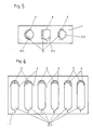
- FIG. 5 Another preferred embodiment of the invention is shown in FIG. 5.
- the carrier material 1 substrates 2 round, square and hexagonal shape, for the removal of which cuts 4 are provided in an angled version.
- the cut can represent two sides of a triangle, three sides of a trapezoid, three sides of a quadrangle or even partial trains of a polygon.
- the gripping sections resulting from the detachment process are again designated by 5.
- FIG. 7 An example of a further preferred embodiment of the invention is shown in FIG. 7.
- FIG. 1 a top view of a section from a band-shaped arrangement is shown, in which the total substrate area divided by adjacent square substrate sections 2, separated from one another only by cut lines, is identical to the area of the carrier material 1.
- a curved cut 4 in the (not visible) carrier material 1 in each corner of each substrate section makes it possible to pull off any substrate 2 independently of the other substrates 2 by means of the grip sections 5 which can be exposed by pressure on the underside of the arrangement.
- FIG. 8 illustrates the applicability of the invention to large-format substrates.
- the top view shows the essentially rectangular substrate 2 with rounded corners, which adheres to a slightly larger substrate 1.
- a curved cutting line 4 is provided in the carrier material, the two ends of which lie within the contact surface.
- the grip section designated 5 can be detached from the carrier material 1.
Abstract
Description
Die Erfindung betrifft eine Abziehhilfe für auf einem flächenförmigen flexiblen Trägermaterial haftende, mechanisch ablösbare Substrate in Form von Schnitten oder Sollbruchlinien im Trägermaterial sowie deren Verwendung.The invention relates to a removal aid for mechanically detachable substrates adhering to a sheet-like flexible carrier material in the form of cuts or predetermined breaking lines in the carrier material and the use thereof.
Insbesondere bezieht sich die Erfindung auf die Trennung von zwei aneinanderhaftenden Materialien, von denen ein Material flächenförmig bzw. folienartig ist, die im Bereich einer Kontaktfläche übereinanderliegen, wie dies bspw. bei Pflastern oder Etiketten, die mit Schutzfolien für Haftklebeschichten ausgerüstet geliefert werden, der Fall ist.In particular, the invention relates to the separation of two mutually adhering materials, one of which is sheet-like or film-like, which lie one above the other in the area of a contact surface, as is the case, for example, with plasters or labels that are supplied equipped with protective films for pressure-sensitive adhesive layers is.
Im folgenden werden die Flächen des Trägermaterials und des Substrats als Kontaktflächen bezeichnet; diese Flächen sind Teilabschnitte einer Trägermaterial- bzw. Substratoberfläche.In the following, the areas of the carrier material and the substrate are referred to as contact areas; these surfaces are subsections of a substrate or substrate surface.
Ferner wird der Ausdruck "Substrat" sowohl für Substratabschnitte oder -teile als auch für das Substrat selbst verwendet.Furthermore, the term "substrate" is used both for substrate sections or parts and for the substrate itself.
Die vorliegende Erfindung bezieht sich demnach auf alle Kombinationen, die eine Substrat/Abdeckfolienkombination demzumindest als Unterkombination aufweisen.The present invention accordingly relates to all combinations which have a substrate / cover film combination at least as a sub-combination.
Die Ablösung einer Abdeckmaterialschicht oder einer Abdeckfolie von einem bspw. mit einer Kleberschicht ausgerüsteten Substrat bereitet insbesondere dann Schwierigkeiten, wenn das Substrat weniger oder in etwa genauso flexi bel wie die Abdeckfolie ist und ganz besonders dann, wenn die durch die Abdeckfolie bedeckte, nach Ablösen derselben ungeschützte Substratoberfläche vor Kontaminationen oder Beschädigungen während der Entfernung der Abziehfolie geschützt werden muß. Ein Grund für den Schutz der Substratkontaktfläche durch eine Abdeckfolie kann bspw. in der Aufrechterhaltung der Eigenklebrigkeit, deren Empfindlichkeit gegenüber mechanischer Beschädigung oder in einer Versiegelung derselben, bspw. gegen das Entweichen flüchtiger Komponenten des Substrats, liegen. Üblicherweise haftet das Trägermaterial, meist eine Folie, durch Adhäsionskräfte am Substrat, die durch Abziehen überwunden werden können.The detachment of a covering material layer or a covering film from a substrate equipped with an adhesive layer, for example, is particularly difficult when the substrate is less flexible or approximately as flexible bel is like the cover film and especially when the covered by the cover film, after removing the same unprotected substrate surface must be protected from contamination or damage during the removal of the release film. One reason for protecting the substrate contact surface by a cover film can be, for example, the maintenance of the inherent stickiness, its sensitivity to mechanical damage or a sealing thereof, for example against the escape of volatile components of the substrate. Usually, the carrier material, usually a film, adheres to the substrate through adhesive forces, which can be overcome by peeling off.
Das Ablösen des Trägermaterials ist häufig problematisch und führt zu Verletzungen der zu schützenden Substratkontaktfläche, wenn bspw. mittels eines Fingernagels, eines Messers oder sonstiger Instrumente versucht wird, auf diesem verbleibende Trägermaterialteile vom Substrat zu entfernen. Dieses Verfahren versagt insbesondere dann, wenn das Verhältnis der Steifigkeit Substrat:Trägermaterial ungünstig ist, z.B. wenn das Trägermaterial sehr viel flexibler als das Substrat ist und auch leicht reißt oder wenn eine sehr weiche Substratkontaktfläche geschützt werden soll.The detachment of the carrier material is often problematic and leads to injuries to the substrate contact surface to be protected if, for example, an attempt is made to remove any remaining carrier material parts from the substrate by means of a fingernail, a knife or other instruments. This method fails particularly if the ratio of the rigidity of substrate: carrier material is unfavorable, e.g. if the carrier material is much more flexible than the substrate and also tears easily or if a very soft substrate contact surface is to be protected.
Insbesondere verbietet sich dieses Verfahren völlig, wenn eine Beeinträchtigung der Substratkontaktfläche durch Berührung - bspw. bei sterilen Flächen von Verbänden, den Steuerschichten von therapeutischen Pflastern oder reaktive Materialen aufweisenden Flächen vermieden werden muß.In particular, this method is completely out of the question if an impairment of the substrate contact surface by contact - for example in the case of sterile surfaces of dressings, the control layers of therapeutic plasters or surfaces having reactive materials must be avoided.
Zur Lösung dieser Problematik ist bereits vorgeschlagen worden, geradlinige Schnitte oder Sollbruchlinien im Trä germaterial vorzusehen, wobei durch Abziehen oder Biegen des Trägermaterials Trägermaterialabschnitte vom Substrat abgelöst werden können.To solve this problem, it has already been proposed to make straight cuts or predetermined breaking lines in the Trä to provide germ material, by pulling or bending the carrier material carrier material sections can be detached from the substrate.
Bisher konnte mittels dieser bekannten Lösungswege noch keine vollständige leichte Freilegung des Substrats, insbesondere dann, wenn es sich um ein relativ inflexibles, empfindliches Substrat - wie ein therapeutisches Pflaster oder bspw. ein Kunststofformteil und eine sehr flexible Trägerfolie, wie eine dünne Aluminiumfolie oder -laminat oder eine Polymerfolie, handelt, erzielt werden.So far, these known solutions have not yet made it possible to completely expose the substrate completely, especially if it is a relatively inflexible, sensitive substrate - such as a therapeutic plaster or, for example, a plastic molding and a very flexible carrier film, such as a thin aluminum film or laminate or a polymer film.
Insbesondere bei kleinen Substratflächen ist es schwierig, diese vollständig freizulegen.Especially with small substrate areas, it is difficult to fully expose them.
Auch das selektive Abziehen einzelner Substratabschnitte von einem Trägermaterial ist nicht zufriedenstellend gelöst.The selective removal of individual substrate sections from a carrier material is also not satisfactorily solved.
Das Vorsehen von gekrümmten Schnitten oder Sollbruchlinien in der Trägerfolie wurde in der US-PS 3 230 649 beschrieben und liefert bei Biegen des Materials die Bildung eines Anfaßabschnittes für einen Teil des Trägermaterials. Der verbleibende Rest muß jedoch noch mühsam mittels des Fingernagels oder eines Hilfswerkzeuges vom Substrat entfernt werden. Ein zufriedenstellendes Verfahren zum vollständigen unbeschädigten Ablösen des Substrats vom Trägermaterial ist dadurch nicht aufgezeigt. Bei mehreren Substratabschnitten auf demselben Trägermaterial kann auch eine Art Ablöseband die Oberflächen mehrerer Substratabschnitte miteinander verbinden, wobei durch Ziehen an einem überstehenden Teil des Bandes die vom Band verbundenen Substratabschnitte durch einen Arbeitsgang vom Trägermaterial abgezogen werden können. Vor Einsatz der Sub stratabschnitte müssen diese jedoch noch vom Ablöseband getrennt werden. Neben der relativ aufwendigen Herstellung dieser bekannten Anordung erlaubt sie nur das Ablösen vom mehreren Substratabschnitten gleichzeitig und ist auf kleindimensionierte Substratabschnitte beschränkt. Das Einlegen von Streifen oder Fäden zwischen Trägermaterial und Substrat, wobei die Streifen oder Fäden über den Rand der Substratabschnitte hinausragen, bietet ebenfalls eine Hilfe zum Ablösen der Substratabschnitte, ist aber mit einer aufwendigen Technologie verbunden.The provision of curved cuts or lines of weakness in the backing sheet has been described in US Pat. No. 3,230,649 and, when the material is bent, provides the formation of a gripping portion for a portion of the backing material. The remaining remainder, however, has to be laboriously removed from the substrate using a fingernail or an auxiliary tool. A satisfactory method for completely undamaged detachment of the substrate from the carrier material is not shown thereby. In the case of a plurality of substrate sections on the same carrier material, a type of release tape can also connect the surfaces of a plurality of substrate sections to one another, the substrate sections connected by the tape being able to be pulled off the carrier material by pulling on a protruding part of the tape. Before using the sub However, strat sections must still be separated from the release belt. In addition to the relatively complex manufacture of this known arrangement, it only allows detachment from several substrate sections at the same time and is limited to small-sized substrate sections. The insertion of strips or threads between the carrier material and the substrate, the strips or threads protruding beyond the edge of the substrate sections, also offers help for detaching the substrate sections, but is associated with a complex technology.
Alle diese Vorschläge führen zu keiner zufriedenstellenden problemlosen Ablösung des Substrates vom Träger unter minimaler Beeinträchtigung des Substrats oder erfordern aufwendige Maßnahmen, wie das Vorsehen von Anfaßbändern.All of these suggestions do not lead to a satisfactory, problem-free detachment of the substrate from the carrier with minimal impairment of the substrate or require complex measures, such as the provision of tapes.
Es ist daher Aufgabe der Erfindung, eine Abziehhilfe für Substrate vom Trägermaterial zu verwirklichen, die die Nachteile des Standes der Technik vermeidet.It is therefore an object of the invention to implement a removal aid for substrates from the carrier material which avoids the disadvantages of the prior art.
Die Aufgabe wird bei einem gattungsgemäßen Gegensstand dadurch gelöst, daß mindestens in der Kontaktfläche des Trägermaterials für jedes Substrat eine gesonderte, nicht geradlinige Schnitt- oder Sollbruchlinie derart vorgesehen ist, daß bei Anwendung von Druck auf das Trägermaterial mit einer Kraftkomponente in Richtung senkrecht zur Substratkontaktfläche ein durch die Schnitt- oder Sollbruchlinie begrenzter Trägermaterialabschnitt mit auf ihm haftendem Substratabschnitt in Richtung des/der Substrats/e biegbar ist, wodurch mindestens ein Teil des Substrats in dessen Randbereich benachbart der Schnitt- oder Sollbruchlinie vom Trägermaterial abgelöst wird und damit ein Anfaßabschnitt am Substrat zum völligen Abziehen des Substrats gebildet wird.The object is achieved with a generic object in that at least in the contact surface of the carrier material for each substrate a separate, non-linear cut or predetermined breaking line is provided such that when pressure is applied to the carrier material with a force component in the direction perpendicular to the substrate contact surface by the cutting or predetermined breaking line limited substrate section with substrate portion adhering to it is bendable in the direction of the substrate (s), whereby at least part of the substrate in its edge region adjacent to the cutting or predetermined breaking line is detached from the substrate and thus a grip portion on the substrate complete stripping of the substrate is formed.
Vorteilhafte Weiterbildungen des Erfindungsgedankens ergeben sich aus den Unteransprüchen.Advantageous developments of the inventive concept result from the subclaims.
Dadurch, daß erfindungsgemäß in jedem Trägermaterialkontaktabschnitt eine gesonderte nicht geradlinige Schnitt- oder Sollbruchlinie vorgesehen ist, ist bei Anwendung von Druck auf die freie Trägermaterialoberfläche im Bereich der Kontaktfläche ein Herausbiegen eines Teilabschnitts des Substrats aus der Kontaktflächenebene heraus möglich, wodurch ein Substrat-Anfaßabschnitt zum völligen Abziehen des Substrats abgelöst wird.Due to the fact that according to the invention a separate non-rectilinear cut or predetermined breaking line is provided in each substrate contact section, when applying pressure to the free substrate surface in the area of the contact surface, a partial section of the substrate can be bent out of the contact surface plane, whereby a substrate grip section for complete Peeling off the substrate is detached.
Hierdurch wird eine vollständige Ablösung des Substrats möglich.This enables the substrate to be completely detached.
Das Trägermaterial und/oder das Substrat können aus mehr als einer Schicht und verschiedenen Materialien aufgebaut sein, wobei bspw. dann, wenn das Substrat ein therapeutisches Pflaster ist, die Substratkontaktflächenschicht ggf. nicht durchgehend aus einheitlichem Material besteht.The carrier material and / or the substrate can be constructed from more than one layer and different materials, for example if the substrate is a therapeutic plaster, the substrate contact surface layer may not consist of a uniform material.
Die dazu einsetzbaren Materialien müssen für das Trägermaterial flexibel und können für das Substrat auch starr sein. So eignen sich als Substrate auch Kunststofformkörper, wie "selbstklebende" Embleme, Wappen od. dgl.. Nach Abziehen des Substrats vom Trägermaterial wird eine Substratschichtoberfläche frei, die bspw. haftklebend ausgerüstet sein kann und/oder aber auch für Wirkstoffe, wie Arzneimittel, durchlässig ist - wie bspw. die Hautkontaktschicht von therapeutischen Pflastern, die nicht notwendigerweise haftklebend sein muß. In letzterem Falle erfüllt das Trägermaterial die Aufgabe einer Sperre, die das unerwünschte Herausdiffundieren von Wirkstoffen aus einem flächenförmigen therapeutischen System verhindert. Dabei ist es nicht unbedingt notwendig, daß die Kontaktfläche eben ist, sie kann auch entsprechend dem Einsatzzweck des Substrats geformt sein.The materials that can be used for this must be flexible for the carrier material and can also be rigid for the substrate. Plastic substrates, such as “self-adhesive” emblems, coats of arms or the like, are also suitable as substrates. After the substrate has been peeled off, a surface of the substrate layer becomes free, which can be provided with a pressure-sensitive adhesive, for example, and / or also permeable to active ingredients, such as medicaments is - such as the skin contact layer of therapeutic plasters, which does not necessarily have to be pressure-sensitive adhesive. In the latter case, the carrier material fulfills the function of a barrier that prevents the undesired diffusion of active ingredients out of a prevents sheet-like therapeutic system. It is not absolutely necessary that the contact surface is flat, it can also be shaped according to the purpose of the substrate.
Die Erzeugung der Sollbruchlinien bzw. von Schnittlinien im Trägermaterial erfolgt nach an sich bekannten Verfahren, bspw. ist für die Herstellung von Schnitten Stanzen, Schneiden, Quetschen oder Prägen des Trägermaterials bevorzugt; es ist aber auch möglich, durch Laser oder Hochfrequenz zu schneiden. Sollbruchlinien können durch Anstanzen, Perforation, lokale chemische oder thermische Behandlung,insbesondere bei Polymerträgermaterialien, durch Laser-Schneiden od. dgl. erzeugt werden, wie es dem Fachmann auf diesem Gebiet geläufig ist. Selbstverständlich können die Linien vor oder nach Aufbringung des/der Substrats/Substrate hergestellt werden.The generation of the predetermined breaking lines or of cutting lines in the carrier material takes place according to methods known per se, for example, punching, cutting, squeezing or embossing of the carrier material is preferred for the production of cuts; but it is also possible to cut by laser or high frequency. Predetermined breaking lines can be produced by punching, perforation, local chemical or thermal treatment, in particular in the case of polymer carrier materials, by laser cutting or the like, as is known to the person skilled in the art in this field. Of course, the lines can be made before or after application of the substrate (s).
Nachfolgend wird die Erfindung anhand von Ausführungsbeispielen anhand der begleitenden Zeichnung näher erläutert, wobei letztere lediglich dem besseren Verständnis dienen und keinesfalls den Schutzbereich des Patentes einschränken sollen. Dabei zeigt:
- Fig. 1 eine Aufsicht auf die Trägermaterialseite einer erfindungsgemäßen Substrat/Trägermaterialkombination mit runden Substraten
- Fig. 2 einen Querschnitt durch die Kombination der Fig.1 entlang der Linie A-B,
- Fig. 3 die Handhabung bei der Ablösung eines Substrats aus der Kombination gemäß Fig.1;
- Fig. 4 die Ablösung eines Substratabschnitts, wie in Fig. 3 gezeigt, in einer Querschnittsansicht;
- Fig. 5 eine Aufsicht auf eine weitere erfindungsgemäße Substrat/Trägermaterial-Kombination mit Schnitt- bzw. Sollbruchlinien gemäß der Erfindung mit verschiedenen Substraten unterschiedlicher geometrischer Gestalt;
- Fig. 6 eine Aufsicht auf eine weitere erfindungsgemäße Substrat/Trägermaterial-Kombination mit oval-länglichen Substraten mit unterschiedlicher Schnittlinienführung;
- Fig. 7 eine Aufsicht auf eine weitere erfindungsgemäße Substrat/Trägerkombination, bei der Trägermaterial und Substrat im wesentlichen die gleiche Fläche aufweisen; und
- Fig. 8 eine Aufsicht auf eine Substrat/Trägerkombination mit großer Substrat/Trägermaterialkontaktfläche.
- Fig. 1 is a plan view of the substrate side of a substrate / substrate combination according to the invention with round substrates
- 2 shows a cross section through the combination of FIG. 1 along the line AB,
- 3 shows the handling when a substrate is detached from the combination according to FIG. 1;
- FIG. 4 shows the detachment of a substrate section, as shown in FIG. 3, in a cross-sectional view;
- 5 shows a plan view of a further substrate / carrier material combination according to the invention with cutting or predetermined breaking lines according to the invention with different substrates of different geometric shape;
- 6 shows a plan view of a further substrate / carrier material combination according to the invention with oval-elongate substrates with different cutting lines;
- 7 shows a plan view of a further substrate / support combination according to the invention, in which the support material and substrate have essentially the same area; and
- 8 is a plan view of a substrate / carrier combination with a large substrate / carrier material contact area.
In Fig. 1 ist eine Ausführungsform einer erfindungsgemäßen Kombination aus Substrat 2 und Trägermaterial 1 schematisch dargestellt, wobei auf einem dünnen, Trägermaterial 1 sechs runde Substrate 2 angeordnet sind. Die Substrate 2 bestehen hier aus einer Nutzschicht 2ʹ, wie bspw. einer Polymerfolie, falls das Substrat ein Etikett ist, es kann aber auch ein in sich komplizierter aufgebautes therapeutisches Pflaster, mit bspw. Abdeckschicht, Wirkstoffreservoir, ggf. weiteren Stütz- und/oder Steuerschichten und einer Haftklebeschicht 3 sein.1 schematically shows an embodiment of a combination of
Das Trägermaterial 1 überragt hier die Kontaktflächen der Substrate 2 allseitig. Im Trägermaterial 1 sind in den Kontaktflächen gekrümmte Schnittlinien 4 angeordnet, die die Ränder der Kontaktfläche schneiden, Die hier mit dem Bezugszeichen 5 bezeichneten Anfaßabschnitte des Substrats gleicher oder geringerer Flexibilität als das Trägermaterial werden beim Ablösevorgang durch Druck auf die freie Trägermaterialoberfläche vom Trägermaterial 1 abgehoben und können nun als Anfaßabschnitte 5 dienen.The
In Fig. 2 ist ein Querschnitt entlang Linie A-B der Fig. 1 dargestellt. Dabei ist im Trägermaterial 1 die Anordung der Schnitte 4 deutlich zu erkennen, die im Bereich der Kontaktfläche zwischen dem sich aus einer Substratnutzschicht 2ʹ und einer Haftkleberschicht 3 zusammensetzenden Substrat 2 und dem Trägermaterial 1 liegen. Der Schnitt 4 ist so weit vom Substratrand entfernt, daß beim Ablösen ein für das Abziehen des gesamten Substrats 2 hinreichend großer Anfaßabschnitt 5 entsteht.FIG. 2 shows a cross section along line A-B of FIG. 1. The arrangement of the
In Fig.3 ist in perspektivischer Darstellung der Einsatz der erfindungsgemäßen Abziehilfe verdeutlicht, wobei gezeigt ist, wie bei Anwendung von Fingerdruck der Anfaßabschnitt 5 eines Substrats freigelegt werden kann. Das Trägermaterial 1 wird hier mit einer Hand gehalten, während mit dem Daumen der anderen Hand von unten ein Abschnitt der Kontaktfläche des Trägermaterials nach oben gedrückt wird. Dabei löst sich, wie die Querschnittsdarstellung in Fig. 4 zeigt, der Anfaßabschnitt 5 vom Trägermaterial 1 ab. In beiden Fig. sind die Schnitte im Trägermaterial mit dem Bezugszeichen 4 bezeichnet.The use of the pull-off aid according to the invention is illustrated in a perspective representation in FIG. 3, it being shown how the
Eine weitere bevorzugte Ausführungsform der Erfindung ist in Fig. 5 dargestellt. Hier haften auf dem Trägermaterial 1 Substrate 2 runder, viereckiger und sechseckiger Form, für deren Ablösung Schnitte 4 in gewinkelter Ausführung vorgesehen sind. So kann der Schnitt zwei Seiten eines Dreiecks, drei Seiten eines Trapezes, drei Seiten eines Vierecks oder auch Teilzüge eines Vielecks darstellen. Die beim Ablösevorgang entstehenden Anfaßabschnitte sind wiederum mit 5 bezeichnet.Another preferred embodiment of the invention is shown in FIG. 5. Here stick to the
In Fig. 6 ist verdeutlicht, daß die Erfindung auch auf Substrate 2 sehr unterschiedlicher Dimensionen anwendbar ist. Es sind 5 Substrate 2 dargestellt, bei denen unterschiedliche mögliche Schnittlinienverläufe vorgesehen sind:
- a: die Schnittlinie schneidet den Rand der Kontaktfläche an zwei Seiten;
- b: die Schnittlinie berührt einen Kontaktflächenrand und schneidet einen anderen Rand der Kontaktfläche;
- c: die Schnittlinie endet einerseits innerhalb und andererseits außerhalb der Kontaktfläche;
- d: die Schnittlinie berührt mit ihren Enden zwei Ränder der Kontaktfläche;
- e: die Schnittlinie berührt mit einem Ende den Kontaktflächenrand, während das andere Ende innerhalb der Kontaktfläche liegt;
- f: beide Schnittlinienenden liegen innerhalb der Kontaktfläche.
- a: the cutting line intersects the edge of the contact surface on two sides;
- b: the cutting line touches one edge of the contact surface and intersects another edge of the contact surface;
- c: the cutting line ends on the one hand inside and on the other hand outside the contact area;
- d: the ends of the cutting line touch two edges of the contact surface;
- e: the cutting line touches one end of the contact surface edge, while the other end lies within the contact surface;
- f: both ends of the cutting line lie within the contact area.
In allen diesen Fällen kann durch Druck auf die freie Fläche des Trägermaterials 1 ein ausreichender Anfaßabschnitt 5 des Substrats 2 freigelegt werden.In all of these cases, pressure can be applied to the free A
Ein Beispiel für eine weitere bevorzugte Ausführungsform der Erfindung ist in Fig. 7 dargestellt.An example of a further preferred embodiment of the invention is shown in FIG. 7.
Hier ist eine Aufsicht auf einen Abschnitt aus einer bandförmigen Anordnung dargestellt, bei der die durch aneinanderliegende quadratische Substratabschnitte 2, nur durch Schnittlinien voneinander getrennt, aufgeteilte Substratgesamtfläche mit der Fläche des Trägermaterials 1 identisch ist. Durch einen gekrümmten Schnitt 4 im (nicht sichtbaren) Trägermaterial 1 in jeweils einer Ecke eines jeden Substratabschnittes ist die Möglichkeit gegeben, mit Hilfe der durch Druck auf die Unterseite der Anordnung freilegbaren Anfaßabschnitte 5 jedes beliebige Substrat 2 unabhängig von den übrigen Substraten 2 abzuziehen.Here a top view of a section from a band-shaped arrangement is shown, in which the total substrate area divided by adjacent
Die Fig. 8 schließlich verdeutlicht die Anwendbarkeit der Erfindung auf großformatige Substrate. In der Aufsicht erkennt man das im wesentlichen rechteckige Substrat 2 mit abgerundeten Ecken, das auf einem flächenmäßig etwas größeren Trägermaterial 1 haftet. In einer Ecke der Kontaktfläche ist im Trägermaterial eine gekrümmte Schnittlinie 4 vorgesehen, deren beide Enden innerhalb der Kontaktfläche liegen. Auch hier läßt sich durch Druck auf die Unterseite des Trägermaterials im Bereich des Schnittes der mit 5 bezeichnete Anfaßabschnitt vom Trägermaterial 1 ablösen.Finally, FIG. 8 illustrates the applicability of the invention to large-format substrates. The top view shows the essentially
Aus der in der Beschreibung erläuterten und in den Figuren dargestellten Ausführungsform ist leicht zu erkennen, daß sich der Erfindung ein sehr breites Anwendungsgebiet eröffnet und diese erhebliche Vorteile bei der Handhabung von Substraten mit Abdeckmaterialien bietet.From the embodiment explained in the description and shown in the figures, it is easy to see that the invention opens up a very wide field of application and that this offers considerable advantages when handling substrates with covering materials.
Claims (10)
Priority Applications (1)
| Application Number | Priority Date | Filing Date | Title |
|---|---|---|---|
| AT88104579T ATE66085T1 (en) | 1987-04-03 | 1988-03-22 | PULLER AND ITS USE. |
Applications Claiming Priority (2)
| Application Number | Priority Date | Filing Date | Title |
|---|---|---|---|
| DE3711256 | 1987-04-03 | ||
| DE19873711256 DE3711256A1 (en) | 1987-04-03 | 1987-04-03 | REMOVAL AID AND THEIR USE |
Publications (2)
| Publication Number | Publication Date |
|---|---|
| EP0284963A1 true EP0284963A1 (en) | 1988-10-05 |
| EP0284963B1 EP0284963B1 (en) | 1991-08-07 |
Family
ID=6324787
Family Applications (1)
| Application Number | Title | Priority Date | Filing Date |
|---|---|---|---|
| EP88104579A Expired - Lifetime EP0284963B1 (en) | 1987-04-03 | 1988-03-22 | Removal aid and its use |
Country Status (28)
| Country | Link |
|---|---|
| US (1) | US5091035A (en) |
| EP (1) | EP0284963B1 (en) |
| JP (1) | JP2888845B2 (en) |
| KR (1) | KR910005518B1 (en) |
| AT (1) | ATE66085T1 (en) |
| AU (1) | AU629791B2 (en) |
| CA (1) | CA1326196C (en) |
| DD (1) | DD268442A5 (en) |
| DE (2) | DE3711256A1 (en) |
| DK (1) | DK162960C (en) |
| ES (1) | ES2025231B3 (en) |
| FI (1) | FI106154B (en) |
| GR (1) | GR3002442T3 (en) |
| HR (1) | HRP920830B1 (en) |
| HU (1) | HU207172B (en) |
| IE (1) | IE60503B1 (en) |
| IL (1) | IL85858A (en) |
| MY (1) | MY103356A (en) |
| NO (1) | NO175997C (en) |
| NZ (1) | NZ223895A (en) |
| PH (1) | PH27604A (en) |
| PL (1) | PL157311B1 (en) |
| PT (1) | PT87143B (en) |
| SI (1) | SI8810637A8 (en) |
| SK (1) | SK204688A3 (en) |
| WO (1) | WO1988007737A1 (en) |
| YU (1) | YU46450B (en) |
| ZA (1) | ZA881740B (en) |
Cited By (7)
| Publication number | Priority date | Publication date | Assignee | Title |
|---|---|---|---|---|
| EP0418607A1 (en) * | 1989-09-16 | 1991-03-27 | LTS LOHMANN THERAPIE-SYSTEME GmbH & CO.KG | Application aid for planar sheet sections |
| EP0418608A1 (en) * | 1989-09-16 | 1991-03-27 | LTS Lohmann Therapie-Systeme GmbH & Co. KG | Application means and its utilization |
| DE3931019A1 (en) * | 1989-09-16 | 1991-03-28 | Lohmann Therapie Syst Lts | Objects e.g. therapeutic systems, plasters and labels |
| WO1998025257A1 (en) * | 1996-12-04 | 1998-06-11 | Hexal Ag | Flat transdermal medicated self-adhesive patch |
| AU695736B3 (en) * | 1998-02-10 | 1998-08-20 | Versari International Limited | A form incorporating a self-adhesive label |
| DE19507120B4 (en) * | 1994-03-02 | 2005-06-30 | Jensen, Kirsten Helvig Berndorff | Final dressing and process for its preparation |
| DE202005012104U1 (en) * | 2005-08-02 | 2006-10-19 | Sca Hygiene Products Gmbh | Packaging foil for e.g. paper tissues, has outer layers made of flexible plastics and comprising recesses provided perpendicular to foil surface, and middle layer provided in between outer layers and made of hard, rough plastics |
Families Citing this family (48)
| Publication number | Priority date | Publication date | Assignee | Title |
|---|---|---|---|---|
| JPH0555173U (en) * | 1991-12-26 | 1993-07-23 | 邦彦 小島 | Label structure |
| DE9203388U1 (en) * | 1992-03-13 | 1992-05-21 | Gizeh-Werk Gmbh, 5275 Bergneustadt, De | |
| US5421933A (en) * | 1992-12-23 | 1995-06-06 | Graydon Wesley Nedblake | System for producing labels from a web |
| DE4307749C2 (en) * | 1993-03-11 | 1998-12-03 | Zweckform Buero Prod Gmbh | Label sheet, manufacturing method and device |
| DE4312446A1 (en) * | 1993-04-16 | 1994-12-15 | Beiersdorf Ag | Label with handle tab |
| DE4321594A1 (en) * | 1993-06-29 | 1995-01-12 | Pacimex Verpackungen Gmbh | Security label and method for its production |
| DE9310258U1 (en) * | 1993-07-09 | 1993-08-26 | Roth Carl Gmbh & Co | Packaging unit for pipette tips |
| JP2722059B2 (en) * | 1995-12-18 | 1998-03-04 | 株式会社日本管理ラベル | Label paper manufacturing method |
| US5775505A (en) * | 1996-02-27 | 1998-07-07 | Vasquez; William M. | Blister card package |
| US5997680A (en) * | 1996-04-30 | 1999-12-07 | Avery Dennison Corporation | Method of producing printed media |
| DE19807970C5 (en) * | 1998-02-25 | 2004-10-14 | Beiersdorf Ag | Release paper with a plurality of plasters arranged thereon, arranged essentially in parallel |
| EP1057749B1 (en) * | 1999-06-02 | 2003-04-02 | Alcan Technology & Management AG | Press-through package |
| DE19956917B4 (en) * | 1999-11-26 | 2006-09-28 | Lohmann & Rauscher Gmbh & Co. Kg | Packaging for plaster |
| US6479118B1 (en) * | 2000-05-04 | 2002-11-12 | Fellowes Inc. | Foldable die cut self-adhesive label sheet for labeling CD-ROMS |
| US9856402B2 (en) | 2003-01-22 | 2018-01-02 | Ccl Lavel, Inc. | Adhesive label liner sheet modifications for retaining unneeded label sections on liner |
| US20050284789A1 (en) * | 2004-06-29 | 2005-12-29 | Carespodi Dennis L | Laser-scored push-through blister backing and methods of making same |
| US20070006713A1 (en) * | 2005-07-08 | 2007-01-11 | Dunlop Manufacturing, Inc. | Guitar pick package |
| JP2007233189A (en) * | 2006-03-02 | 2007-09-13 | Nippon Paper Industries Co Ltd | Band-like label sheet |
| ES2340958T3 (en) * | 2007-01-22 | 2010-06-11 | Edwin Kohl | PACKAGING OF BLISTERS AND PROCEDURE FOR THE PROVISIONAL STORAGE OF PRODUCTS. |
| AU2007100655A4 (en) * | 2007-07-18 | 2007-08-16 | Manrex Pty. Ltd. | Improvements in Blister Backing Strips |
| US8273436B2 (en) * | 2007-09-17 | 2012-09-25 | Flynn Timothy J | Separatable label assembly |
| US20100233411A1 (en) * | 2009-03-12 | 2010-09-16 | Flynn Timothy J | Apparatus for separating label assembly |
| JP5235384B2 (en) | 2007-11-08 | 2013-07-10 | リンテック株式会社 | Attached sheet |
| AU2009240507B2 (en) * | 2008-04-24 | 2014-12-18 | Ccl Label, Inc. | Sheet having removable labels and related method |
| JP5537081B2 (en) | 2009-07-28 | 2014-07-02 | 浜松ホトニクス株式会社 | Processing object cutting method |
| US9138378B2 (en) * | 2011-07-06 | 2015-09-22 | Sonoco Development, Inc. | Blister package and method of forming same |
| US20140238215A1 (en) * | 2013-02-27 | 2014-08-28 | Alta Paterson | Pick stabilization device |
| CN105321421B (en) * | 2014-07-04 | 2018-08-07 | 青岛海尔空调器有限总公司 | A kind of labeling component |
| US9852661B2 (en) | 2015-02-20 | 2017-12-26 | Ccl Label, Inc. | Self laminating labels |
| EP3365885A1 (en) | 2015-10-23 | 2018-08-29 | CCL Label, Inc. | Label sheet assembly with improved printer feeding |
| USD813942S1 (en) | 2016-02-04 | 2018-03-27 | Ccl Label, Inc. | Label sheets |
| USD813945S1 (en) | 2016-03-22 | 2018-03-27 | Ccl Label, Inc. | Label sheet |
| USD862601S1 (en) | 2016-07-07 | 2019-10-08 | Ccl Label, Inc. | Carrier assembly |
| USD889258S1 (en) * | 2016-08-04 | 2020-07-07 | Carolin McKie | Beverage container identification marker kit |
| US11049420B2 (en) | 2016-11-15 | 2021-06-29 | Ccl Label, Inc. | Label sheet assembly with surface features |
| USD841087S1 (en) | 2016-11-17 | 2019-02-19 | Ccl Label, Inc. | Label sheet with a feed edge assembly |
| USD813944S1 (en) | 2017-03-13 | 2018-03-27 | Ccl Label, Inc. | Label sheet assembly |
| USD853480S1 (en) | 2017-05-10 | 2019-07-09 | Ccl Label, Inc. | Label sheet assembly |
| US11279162B2 (en) | 2018-03-01 | 2022-03-22 | Ccl Label, Inc. | Sheet with feeding perforation |
| USD856414S1 (en) | 2018-03-01 | 2019-08-13 | Ccl Label, Inc. | Label sheet assembly with feed edge dress |
| USD893606S1 (en) | 2018-03-23 | 2020-08-18 | Ccl Label, Inc. | Name badge sheet assembly |
| USD877241S1 (en) | 2018-06-08 | 2020-03-03 | Ccl Label, Inc. | Label sheet layout assembly |
| USD914085S1 (en) | 2018-08-29 | 2021-03-23 | Ccl Label, Inc. | Label sheet layout assemblies |
| USD943668S1 (en) | 2019-05-01 | 2022-02-15 | Ccl Label, Inc. | Label sheet with surface texture assembly |
| TWI741411B (en) * | 2019-11-25 | 2021-10-01 | 兆宣精密印刷有限公司 | Label sticker |
| USD947280S1 (en) | 2020-03-31 | 2022-03-29 | Ccl Label, Inc. | Label sheet assembly with matrix cuts |
| USD968509S1 (en) | 2020-07-02 | 2022-11-01 | Ccl Label, Inc. | Label sheet assembly with raised tactile features |
| CA3115628A1 (en) | 2020-07-02 | 2022-01-02 | Ccl Label, Inc. | Label sheet assembly with puncture surface features |
Citations (6)
| Publication number | Priority date | Publication date | Assignee | Title |
|---|---|---|---|---|
| US3230649A (en) * | 1963-07-12 | 1966-01-25 | Andrew B Karn | Continuous, cut-back, pressure-sensitive label stock and labels |
| US3361252A (en) * | 1967-01-25 | 1968-01-02 | Brady Co W H | Articulated label storage cards |
| US3690999A (en) * | 1970-04-28 | 1972-09-12 | Dennison Mfg Co | Precut composite tape structure |
| DE2407822A1 (en) * | 1974-02-19 | 1975-08-28 | Schneider & Soehne Kg G | Self-adhesive data carrier especially label - incorporates pressure sensitive capsules which combine with reagent layer to produce coloured image |
| US4335172A (en) * | 1977-03-28 | 1982-06-15 | Kabushiki Kaisha Sato | Pressure sensitive label strip |
| EP0102599A1 (en) * | 1982-09-06 | 1984-03-14 | Kabushiki Kaisha Sato | Label strip |
Family Cites Families (4)
| Publication number | Priority date | Publication date | Assignee | Title |
|---|---|---|---|---|
| US3501365A (en) * | 1969-07-11 | 1970-03-17 | Litton Business Systems Inc | Pressure sensitive label strip construction |
| US4210688A (en) * | 1977-03-28 | 1980-07-01 | Kabushiki Kaisha Sato | Pressure sensitive label strip for use in a label printing machine |
| US4305767A (en) * | 1979-03-07 | 1981-12-15 | Corey Jan M | Label system for making integrated circuit diagrams and printed circuit boards |
| DE3315271C1 (en) * | 1983-04-27 | 1984-10-31 | Lohmann Gmbh & Co Kg, 5450 Neuwied | Laminate sections with cover and peel aid for this |
-
1987
- 1987-04-03 DE DE19873711256 patent/DE3711256A1/en active Granted
-
1988
- 1988-03-11 ZA ZA881740A patent/ZA881740B/en unknown
- 1988-03-14 PH PH36636A patent/PH27604A/en unknown
- 1988-03-15 NZ NZ223895A patent/NZ223895A/en unknown
- 1988-03-18 MY MYPI88000277A patent/MY103356A/en unknown
- 1988-03-22 JP JP63502404A patent/JP2888845B2/en not_active Expired - Lifetime
- 1988-03-22 AT AT88104579T patent/ATE66085T1/en active
- 1988-03-22 WO PCT/DE1988/000181 patent/WO1988007737A1/en active IP Right Grant
- 1988-03-22 ES ES88104579T patent/ES2025231B3/en not_active Expired - Lifetime
- 1988-03-22 EP EP88104579A patent/EP0284963B1/en not_active Expired - Lifetime
- 1988-03-22 DE DE8888104579T patent/DE3864048D1/en not_active Expired - Lifetime
- 1988-03-22 AU AU13959/88A patent/AU629791B2/en not_active Ceased
- 1988-03-22 KR KR1019880701382A patent/KR910005518B1/en not_active IP Right Cessation
- 1988-03-22 HU HU881860A patent/HU207172B/en not_active IP Right Cessation
- 1988-03-22 IE IE83388A patent/IE60503B1/en not_active IP Right Cessation
- 1988-03-24 IL IL85858A patent/IL85858A/en not_active IP Right Cessation
- 1988-03-25 CA CA000562579A patent/CA1326196C/en not_active Expired - Fee Related
- 1988-03-28 SK SK2046-88A patent/SK204688A3/en unknown
- 1988-03-30 SI SI8810637A patent/SI8810637A8/en unknown
- 1988-03-30 YU YU63788A patent/YU46450B/en unknown
- 1988-03-31 DD DD31428588A patent/DD268442A5/en unknown
- 1988-03-31 PT PT87143A patent/PT87143B/en not_active IP Right Cessation
- 1988-03-31 PL PL1988271543A patent/PL157311B1/en unknown
- 1988-10-03 NO NO884381A patent/NO175997C/en not_active IP Right Cessation
- 1988-11-29 DK DK666088A patent/DK162960C/en not_active IP Right Cessation
- 1988-12-01 FI FI885599A patent/FI106154B/en not_active IP Right Cessation
-
1990
- 1990-11-08 US US07/610,447 patent/US5091035A/en not_active Expired - Fee Related
-
1991
- 1991-08-08 GR GR91400978T patent/GR3002442T3/en unknown
-
1992
- 1992-10-02 HR HRP-637/88A patent/HRP920830B1/en not_active IP Right Cessation
Patent Citations (6)
| Publication number | Priority date | Publication date | Assignee | Title |
|---|---|---|---|---|
| US3230649A (en) * | 1963-07-12 | 1966-01-25 | Andrew B Karn | Continuous, cut-back, pressure-sensitive label stock and labels |
| US3361252A (en) * | 1967-01-25 | 1968-01-02 | Brady Co W H | Articulated label storage cards |
| US3690999A (en) * | 1970-04-28 | 1972-09-12 | Dennison Mfg Co | Precut composite tape structure |
| DE2407822A1 (en) * | 1974-02-19 | 1975-08-28 | Schneider & Soehne Kg G | Self-adhesive data carrier especially label - incorporates pressure sensitive capsules which combine with reagent layer to produce coloured image |
| US4335172A (en) * | 1977-03-28 | 1982-06-15 | Kabushiki Kaisha Sato | Pressure sensitive label strip |
| EP0102599A1 (en) * | 1982-09-06 | 1984-03-14 | Kabushiki Kaisha Sato | Label strip |
Cited By (9)
| Publication number | Priority date | Publication date | Assignee | Title |
|---|---|---|---|---|
| EP0418607A1 (en) * | 1989-09-16 | 1991-03-27 | LTS LOHMANN THERAPIE-SYSTEME GmbH & CO.KG | Application aid for planar sheet sections |
| EP0418608A1 (en) * | 1989-09-16 | 1991-03-27 | LTS Lohmann Therapie-Systeme GmbH & Co. KG | Application means and its utilization |
| DE3931019A1 (en) * | 1989-09-16 | 1991-03-28 | Lohmann Therapie Syst Lts | Objects e.g. therapeutic systems, plasters and labels |
| DE3931018A1 (en) * | 1989-09-16 | 1991-05-16 | Lohmann Therapie Syst Lts | APPLICATION AID FOR FLAT SUBSTRATE SECTIONS |
| DE19507120B4 (en) * | 1994-03-02 | 2005-06-30 | Jensen, Kirsten Helvig Berndorff | Final dressing and process for its preparation |
| WO1998025257A1 (en) * | 1996-12-04 | 1998-06-11 | Hexal Ag | Flat transdermal medicated self-adhesive patch |
| AU725503B2 (en) * | 1996-12-04 | 2000-10-12 | Hexal Ag | Flat self-adhering drug patches |
| AU695736B3 (en) * | 1998-02-10 | 1998-08-20 | Versari International Limited | A form incorporating a self-adhesive label |
| DE202005012104U1 (en) * | 2005-08-02 | 2006-10-19 | Sca Hygiene Products Gmbh | Packaging foil for e.g. paper tissues, has outer layers made of flexible plastics and comprising recesses provided perpendicular to foil surface, and middle layer provided in between outer layers and made of hard, rough plastics |
Also Published As
Similar Documents
| Publication | Publication Date | Title |
|---|---|---|
| EP0284963B1 (en) | Removal aid and its use | |
| EP0418608B1 (en) | Application means and its utilization | |
| DE3931018C2 (en) | ||
| DE3315271C1 (en) | Laminate sections with cover and peel aid for this | |
| EP0845517B1 (en) | Use of a section of adhesive tape | |
| DE4428587C2 (en) | Adhesive film strips | |
| DE3344334A1 (en) | FILM BANDAGE AND METHOD FOR ITS APPLICATION | |
| DE3344335A1 (en) | LAMINATE SECTIONS WITH COVER AND REMOVAL AID THEREFOR | |
| DE3317929A1 (en) | Wound bandage laminate | |
| EP0943138B1 (en) | Flat transdermal medicated self-adhesive patch | |
| WO2006092248A2 (en) | Film structure with improved application assistance | |
| EP1394600B1 (en) | Multilayer label | |
| DE3931019C2 (en) | ||
| DE19807970C1 (en) | Separation paper with several parallel plasters | |
| EP0326139A2 (en) | Self-adhesive label and the manufacture thereof | |
| DE2132084C2 (en) | Flexible laminate | |
| EP2611430B1 (en) | Protective-film changer | |
| EP1629810B1 (en) | Laminated plaster and method of production | |
| DE3832662A1 (en) | DRY-TRANSFERABLE, THROUGH-SENSITIVE ADHESIVE FILM | |
| DE102011106156B4 (en) | COATING SYSTEM FOR APPLICATION TO A SUPPORT, USE AND METHOD OF APPLYING AN APPLICATION LAYER ARRANGEMENT | |
| EP2999443B1 (en) | Plaster comprising peeling aid | |
| WO2007090592A1 (en) | Film structure with improved application assistance | |
| DE102004039514A1 (en) | Method for closing wounds comprises applying several narrow strips of special sticking plaster to hold the edges of the wound together |
Legal Events
| Date | Code | Title | Description |
|---|---|---|---|
| PUAI | Public reference made under article 153(3) epc to a published international application that has entered the european phase |
Free format text: ORIGINAL CODE: 0009012 |
|
| AK | Designated contracting states |
Kind code of ref document: A1 Designated state(s): AT BE CH DE ES FR GB GR IT LI LU NL SE |
|
| 17P | Request for examination filed |
Effective date: 19881024 |
|
| 17Q | First examination report despatched |
Effective date: 19901211 |
|
| GRAA | (expected) grant |
Free format text: ORIGINAL CODE: 0009210 |
|
| AK | Designated contracting states |
Kind code of ref document: B1 Designated state(s): AT BE CH DE ES FR GB GR IT LI LU NL SE |
|
| REF | Corresponds to: |
Ref document number: 66085 Country of ref document: AT Date of ref document: 19910815 Kind code of ref document: T |
|
| REF | Corresponds to: |
Ref document number: 3864048 Country of ref document: DE Date of ref document: 19910912 |
|
| ITF | It: translation for a ep patent filed |
Owner name: STUDIO TORTA SOCIETA' SEMPLICE |
|
| GBT | Gb: translation of ep patent filed (gb section 77(6)(a)/1977) | ||
| ET | Fr: translation filed | ||
| REG | Reference to a national code |
Ref country code: ES Ref legal event code: FG2A Ref document number: 2025231 Country of ref document: ES Kind code of ref document: B3 |
|
| PLBE | No opposition filed within time limit |
Free format text: ORIGINAL CODE: 0009261 |
|
| STAA | Information on the status of an ep patent application or granted ep patent |
Free format text: STATUS: NO OPPOSITION FILED WITHIN TIME LIMIT |
|
| 26N | No opposition filed | ||
| REG | Reference to a national code |
Ref country code: GR Ref legal event code: FG4A Free format text: 3002442 |
|
| EPTA | Lu: last paid annual fee | ||
| EAL | Se: european patent in force in sweden |
Ref document number: 88104579.3 |
|
| PGFP | Annual fee paid to national office [announced via postgrant information from national office to epo] |
Ref country code: GB Payment date: 20010214 Year of fee payment: 14 |
|
| PGFP | Annual fee paid to national office [announced via postgrant information from national office to epo] |
Ref country code: CH Payment date: 20010219 Year of fee payment: 14 |
|
| PGFP | Annual fee paid to national office [announced via postgrant information from national office to epo] |
Ref country code: LU Payment date: 20010223 Year of fee payment: 14 |
|
| PGFP | Annual fee paid to national office [announced via postgrant information from national office to epo] |
Ref country code: AT Payment date: 20010226 Year of fee payment: 14 |
|
| PGFP | Annual fee paid to national office [announced via postgrant information from national office to epo] |
Ref country code: NL Payment date: 20010228 Year of fee payment: 14 Ref country code: GR Payment date: 20010228 Year of fee payment: 14 |
|
| PGFP | Annual fee paid to national office [announced via postgrant information from national office to epo] |
Ref country code: SE Payment date: 20010305 Year of fee payment: 14 |
|
| PGFP | Annual fee paid to national office [announced via postgrant information from national office to epo] |
Ref country code: BE Payment date: 20010309 Year of fee payment: 14 |
|
| PGFP | Annual fee paid to national office [announced via postgrant information from national office to epo] |
Ref country code: FR Payment date: 20010313 Year of fee payment: 14 Ref country code: DE Payment date: 20010313 Year of fee payment: 14 |
|
| PGFP | Annual fee paid to national office [announced via postgrant information from national office to epo] |
Ref country code: ES Payment date: 20010316 Year of fee payment: 14 |
|
| REG | Reference to a national code |
Ref country code: GB Ref legal event code: IF02 |
|
| PG25 | Lapsed in a contracting state [announced via postgrant information from national office to epo] |
Ref country code: LU Free format text: LAPSE BECAUSE OF NON-PAYMENT OF DUE FEES Effective date: 20020322 Ref country code: GB Free format text: LAPSE BECAUSE OF NON-PAYMENT OF DUE FEES Effective date: 20020322 Ref country code: AT Free format text: LAPSE BECAUSE OF NON-PAYMENT OF DUE FEES Effective date: 20020322 |
|
| PG25 | Lapsed in a contracting state [announced via postgrant information from national office to epo] |
Ref country code: SE Free format text: LAPSE BECAUSE OF NON-PAYMENT OF DUE FEES Effective date: 20020323 Ref country code: ES Free format text: LAPSE BECAUSE OF NON-PAYMENT OF DUE FEES Effective date: 20020323 |
|
| PG25 | Lapsed in a contracting state [announced via postgrant information from national office to epo] |
Ref country code: LI Free format text: LAPSE BECAUSE OF NON-PAYMENT OF DUE FEES Effective date: 20020331 Ref country code: CH Free format text: LAPSE BECAUSE OF NON-PAYMENT OF DUE FEES Effective date: 20020331 Ref country code: BE Free format text: LAPSE BECAUSE OF NON-PAYMENT OF DUE FEES Effective date: 20020331 |
|
| BERE | Be: lapsed |
Owner name: LOHMANN THERAPIE-SYSTEME G.M.B.H. & CO. K.G. *LTS Effective date: 20020331 |
|
| PG25 | Lapsed in a contracting state [announced via postgrant information from national office to epo] |
Ref country code: NL Free format text: LAPSE BECAUSE OF NON-PAYMENT OF DUE FEES Effective date: 20021001 Ref country code: DE Free format text: LAPSE BECAUSE OF NON-PAYMENT OF DUE FEES Effective date: 20021001 |
|
| PG25 | Lapsed in a contracting state [announced via postgrant information from national office to epo] |
Ref country code: GR Free format text: LAPSE BECAUSE OF NON-PAYMENT OF DUE FEES Effective date: 20021007 |
|
| EUG | Se: european patent has lapsed |
Ref document number: 88104579.3 |
|
| GBPC | Gb: european patent ceased through non-payment of renewal fee |
Effective date: 20020322 |
|
| REG | Reference to a national code |
Ref country code: CH Ref legal event code: PL |
|
| PG25 | Lapsed in a contracting state [announced via postgrant information from national office to epo] |
Ref country code: FR Free format text: LAPSE BECAUSE OF NON-PAYMENT OF DUE FEES Effective date: 20021129 |
|
| NLV4 | Nl: lapsed or anulled due to non-payment of the annual fee |
Effective date: 20021001 |
|
| REG | Reference to a national code |
Ref country code: FR Ref legal event code: ST |
|
| REG | Reference to a national code |
Ref country code: ES Ref legal event code: FD2A Effective date: 20030410 |
|
| PG25 | Lapsed in a contracting state [announced via postgrant information from national office to epo] |
Ref country code: IT Free format text: LAPSE BECAUSE OF NON-PAYMENT OF DUE FEES;WARNING: LAPSES OF ITALIAN PATENTS WITH EFFECTIVE DATE BEFORE 2007 MAY HAVE OCCURRED AT ANY TIME BEFORE 2007. THE CORRECT EFFECTIVE DATE MAY BE DIFFERENT FROM THE ONE RECORDED. Effective date: 20050322 |