EP0284491A1 - Farbfernsehröhre mit einer wenig verbrauchenden Ablenkung - Google Patents
Farbfernsehröhre mit einer wenig verbrauchenden Ablenkung Download PDFInfo
- Publication number
- EP0284491A1 EP0284491A1 EP88400608A EP88400608A EP0284491A1 EP 0284491 A1 EP0284491 A1 EP 0284491A1 EP 88400608 A EP88400608 A EP 88400608A EP 88400608 A EP88400608 A EP 88400608A EP 0284491 A1 EP0284491 A1 EP 0284491A1
- Authority
- EP
- European Patent Office
- Prior art keywords
- winding
- deflector
- tube
- horizontal
- neck
- Prior art date
- Legal status (The legal status is an assumption and is not a legal conclusion. Google has not performed a legal analysis and makes no representation as to the accuracy of the status listed.)
- Granted
Links
Images

Classifications
-
- H—ELECTRICITY
- H01—ELECTRIC ELEMENTS
- H01J—ELECTRIC DISCHARGE TUBES OR DISCHARGE LAMPS
- H01J29/00—Details of cathode-ray tubes or of electron-beam tubes of the types covered by group H01J31/00
- H01J29/46—Arrangements of electrodes and associated parts for generating or controlling the ray or beam, e.g. electron-optical arrangement
- H01J29/70—Arrangements for deflecting ray or beam
- H01J29/72—Arrangements for deflecting ray or beam along one straight line or along two perpendicular straight lines
- H01J29/76—Deflecting by magnetic fields only
- H01J29/766—Deflecting by magnetic fields only using a combination of saddle coils and toroidal windings
Definitions
- the invention relates to a mask type color television tube.
- a color television tube is constituted by a vacuum glass ampoule comprising a front wall, or slab, on the internal face of which the phosphors constituting the screen are deposited and a cylindrical rear part, called neck, containing the, or them, electron gun (s), and connected to the slab by a flared part.
- the deflection of the electron beams is obtained using magnetic fields produced by a vertical deflection winding and a horizontal deflection winding.
- the horizontal deflection winding, or line deflector makes it possible to scan the electron beam along horizontal lines and the vertical deflection winding, or weft deflector, ensures the passage from one line to another. These two windings are arranged around the neck and the flared part.
- a perforated mask is generally provided, placed inside the tube at short distance of the screen, the arrangement of the barrels and the holes of the mask being such as to allow this selection of colors.
- this diameter is of the order of 22 millimeters and in the second type, the diameter is of the order of 29 millimeters. These diameters are independent of the size of the screen.
- the advantage of the small diameter neck tube is, on the one hand, its small size and therefore its low material cost and on the other hand that the energy supplied to the deflector is relatively low, this deflector being not far from the electron beams.
- the disadvantage of this type of tube is that the focusing of the beams is not always satisfactory; and the vacuum is more difficult to obtain there.
- the neck tube of larger diameter of the order of 29 millimeters, it is easier to evacuate and the performance of the electron guns is also superior to that of the barrels of small diameter tubes.
- the deflector of the larger diameter neck tube consumes more energy and is more expensive.
- the different characteristics of the deflectors lead to different characteristics of the television receiver circuits associated with these tubes.
- a type of tube there must be a determined type of associated circuit.
- the invention combines the advantages of the two types of tubes mentioned above.
- the color television tube is formed by the combination on the one hand of a neck glass bulb with a diameter of approximately 29 millimeters with the corresponding electron guns inside, and on the other hand d '' a diverter whose line winding has a relationship L R , L being the inductance and R the resistance, between approximately 630 and 730 microseconds, preferably of the order of 670 microseconds.
- Such a color television tube has the advantage of large diameter neck tubes, that is to say the good quality of the image obtained, and on the other hand, surprisingly, despite the greater distances between the deflector and the electron beams, the electrical energy consumption of this deflector is of the same order of magnitude as with a tube with a neck diameter of 22 millimeters.
- the conical part of the glass bulb (funnel)
- corresponding to the deflection zone is for example of the type of that of the tube "coty - 29" type 90 ° sold by RCA.
- the tube according to the invention has a glass bulb 10 with associated barrels, with a conical part of the "coty-29" type from RCA with a neck 11 with an outside diameter of approximately 29 millimeters.
- the deflector 12 differs from that of the "coty-29" tube by the fact that the ratio L R of the line diverter is between 630 and 730 microseconds, preferably of the order of 670 microseconds.
- the dimensions, size and consumption of the deflector of the tube according to the invention are lower than the corresponding values for the tube "coty - 29".
- This deflector 12 extends partly around the neck 11 and partly around the flared part 13.
- the support 14 made of non-magnetic material, for example plastic material, enclosing the horizontal deflection winding 15 (line deflector) in the form of a saddle.
- the vertical deflection coil 16 (weft deflector) is in the form of a torus and is wound around a magnetic core 17 made of ferrite. This weft deflector is carried by the support 14.
- the shapes and dimensions of the support 14, of the core 17 and of the winding 16 are such that, even before mounting, that is to say before fixing the weft deflector 16,17 to the support 14, there is hardly any play in the direction perpendicular to the axis 11a of the tube for the vertical deflector.
- This characteristic is certainly a drawback because it prevents a convergence adjustment during assembly of the deflector, but it makes it possible, by bringing the weft deflector closer to the axis 11a, to minimize the current consumption of this weft deviator.
- the support 14 has a rear ring 18 enclosing the rear buns 19 of the horizontal deflection winding 15. This support 14 also has a front ring housing the front buns of the horizontal winding 15.
- the vertical deflection coil 16 has two parts 161 and 162 leaving between them two large intervals 171 and 172 of the core 17 which are not surrounded by a coil.
- Each part 171 or 172 not covered with the core 17 has dimensions of the same order of magnitude as those of each part covered by a coil 161 or 162.
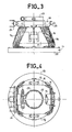
- the rear part 22 of the support 14 is cylindrical with an internal diameter of the order of 30 millimeters.
- the smallest diameter of the inner surface of the core 17 is of the order of 40 millimeters while the largest diameter of the internal surface of this core 17 is of the order of 70 millimeters.
- the length L1 (FIG. 1) of the core 17 along the axis 11a is 37 millimeters.
- the length L2 separating the flanges closest to the housings 18 and 20 is 45 millimeters.
- the total length of the support 14, still along the axis 11a, is 66.5 millimeters.
- the largest diameter of the diverter that is to say that of the housing 20, is 96 millimeters.
- the part 22, which is crenellated to present flexibility and to be applied against the neck, is surrounded by a clamp 23 (FIG. 4) and the crown 18 of the support. 14 shows the connections 24 to the power supply circuit as well as projections 25 for snap-fastening in the cabinet of a television receiver.
- the energy consumption of the line winding is less than approximately 1.6 millijoule and the power of the frame winding is 2.5 Watts, for a high voltage of 25 kV, that is to say the same level of energy as that supplied by the electronic circuits of the chassis associated with 22 mm diameter neck tubes.
Landscapes
- Video Image Reproduction Devices For Color Tv Systems (AREA)
- Vessels, Lead-In Wires, Accessory Apparatuses For Cathode-Ray Tubes (AREA)
Applications Claiming Priority (2)
| Application Number | Priority Date | Filing Date | Title |
|---|---|---|---|
| FR8703926 | 1987-03-20 | ||
| FR8703926A FR2612693B1 (fr) | 1987-03-20 | 1987-03-20 | Tube de television en couleurs a deviateur de faible consommation |
Publications (2)
| Publication Number | Publication Date |
|---|---|
| EP0284491A1 true EP0284491A1 (de) | 1988-09-28 |
| EP0284491B1 EP0284491B1 (de) | 1992-08-26 |
Family
ID=9349267
Family Applications (1)
| Application Number | Title | Priority Date | Filing Date |
|---|---|---|---|
| EP88400608A Expired - Lifetime EP0284491B1 (de) | 1987-03-20 | 1988-03-15 | Farbfernsehröhre mit einer wenig verbrauchenden Ablenkung |
Country Status (7)
| Country | Link |
|---|---|
| EP (1) | EP0284491B1 (de) |
| JP (1) | JPS63254644A (de) |
| KR (1) | KR960008602B1 (de) |
| CN (1) | CN1013535B (de) |
| DE (1) | DE3873948T2 (de) |
| FR (1) | FR2612693B1 (de) |
| HK (1) | HK88797A (de) |
Family Cites Families (2)
| Publication number | Priority date | Publication date | Assignee | Title |
|---|---|---|---|---|
| JPS5618655B2 (de) * | 1971-08-13 | 1981-04-30 | ||
| US4376924A (en) * | 1982-06-04 | 1983-03-15 | Rca Corporation | Self-converging television display system |
-
1987
- 1987-03-20 FR FR8703926A patent/FR2612693B1/fr not_active Expired
-
1988
- 1988-01-12 CN CN88100175A patent/CN1013535B/zh not_active Expired
- 1988-03-15 EP EP88400608A patent/EP0284491B1/de not_active Expired - Lifetime
- 1988-03-15 DE DE8888400608T patent/DE3873948T2/de not_active Expired - Fee Related
- 1988-03-17 KR KR1019880002827A patent/KR960008602B1/ko not_active Expired - Fee Related
- 1988-03-22 JP JP63068020A patent/JPS63254644A/ja active Pending
-
1997
- 1997-06-26 HK HK88797A patent/HK88797A/xx not_active IP Right Cessation
Non-Patent Citations (2)
| Title |
|---|
| IEEE TRANSACTIONS ON CONSUMER ELECTRONICS, vol. CE-29, no. 4, novembre 1983, pages 486-490, IEEE, New York, US; J. GROSS et al.: "Deflection-yoke design for the COTY-29 color-picture tube display system" * |
| RADIO ENGINEERING, vol. 25, no. 4, 1970, pages 105-109, Washington, US; D.P. BRILLIANTOV et al.: "Design of magnetic deflecting systems of maximum effectiveness" * |
Also Published As
| Publication number | Publication date |
|---|---|
| DE3873948T2 (de) | 1993-02-04 |
| HK88797A (en) | 1997-06-27 |
| FR2612693A1 (fr) | 1988-09-23 |
| FR2612693B1 (fr) | 1989-05-26 |
| DE3873948D1 (de) | 1992-10-01 |
| EP0284491B1 (de) | 1992-08-26 |
| JPS63254644A (ja) | 1988-10-21 |
| CN1013535B (zh) | 1991-08-14 |
| CN88100175A (zh) | 1988-10-05 |
| KR880011871A (ko) | 1988-10-31 |
| KR960008602B1 (ko) | 1996-06-28 |
Similar Documents
| Publication | Publication Date | Title |
|---|---|---|
| FR2493039A1 (fr) | Perfectionnements apportes aux canons electroniques des tubes images couleurs pour reduire l'aberration spherique | |
| FR2541817A1 (fr) | Tube a rayons cathodiques presentant un contour ameliore de masque d'ombre | |
| FR2559948A1 (fr) | Tube image couleur comportant un dispositif de correction d'astigmatisme | |
| FR2541820A1 (fr) | Tube a rayons cathodiques comportant un panneau de plaque frontale ayant une peripherie sensiblement plane | |
| FR2477316A1 (fr) | Tube-image couleur comportant des canons electroniques en ligne | |
| FR2545647A1 (fr) | Tube a rayons cathodiques comportant une grille ecran, et grille astigmatique pour un tel tube | |
| FR2561440A1 (fr) | Systeme d'affichage d'images en couleur comprenant un blindage magnetique externe | |
| FR2487119A1 (fr) | Tube d'images en couleur muni d'une electrode de selection de couleur suspendue dans les angles de la fenetre d'image | |
| FR2545980A1 (fr) | Moyen de correction de distorsion en coussinet de la trame par modification des champs externes du bobinage deflecteur du televiseur | |
| EP0284491B1 (de) | Farbfernsehröhre mit einer wenig verbrauchenden Ablenkung | |
| FR2757681A1 (fr) | Systeme de deviation pour tube a rayons cathodiques adapte au controle de la geometrie nord/sud de l'image | |
| FR2528231A1 (fr) | Systeme autoconvergent de visualisation de television | |
| FR2476387A1 (fr) | Tube a rayons cathodiques plat et compact | |
| FR2705164A1 (fr) | Tube image couleurs à canons à électrons en ligne avec lentilles astigmatiques. | |
| FR2581245A1 (fr) | Tube a rayons cathodiques comportant une grille d'ecran a moyens de focalisation de faisceaux asymetriques et lentilles de refraction | |
| FR2476909A1 (fr) | Dispositif de compensation dans un televiseur en couleur, pour ameliorer la convergence | |
| EP0635163B1 (de) | Selbstkonvergierende und in der geometrie korrigierte elektronenablenkeinheit für kathodenstrahlröhren | |
| EP0107987B2 (de) | Verfahren zur Änderung einer Ablenkeinheit das seine Verwendung in autokonvergierenden Bildröhren verschiedener Grösse ermöglicht und auf diese Weise erhaltene Ablenkeinheit | |
| EP0125949B1 (de) | Farbfernsehröhre mit einer Korrektur von Komafehlern geringer Amplitude | |
| FR2505088A1 (fr) | Canon a electrons muni d'une region de formation de faisceaux amelioree, tube cathodique et recepteur de television pourvu d'un tel tube | |
| FR2586326A1 (fr) | Canon a electrons pour tube a rayons cathodiques, notamment pour la television en couleurs | |
| FR2682809A1 (fr) | Tube a rayons cathodiques a canon a electrons ameliore. | |
| FR2766612A1 (fr) | Deviateur pour tube a rayons cathodiques a geometrie et convergence ameliorees | |
| CA1248576A (fr) | Canon a electrons pour tube a rayons cathodiques ayant une lueur de cathode reduite | |
| FR2505090A1 (fr) | Canon electronique comportant une region perfectionnee de formation de faisceaux, tube a rayons cathodiques, et recepteur de television muni d'un tel tube cathodique |
Legal Events
| Date | Code | Title | Description |
|---|---|---|---|
| PUAI | Public reference made under article 153(3) epc to a published international application that has entered the european phase |
Free format text: ORIGINAL CODE: 0009012 |
|
| AK | Designated contracting states |
Kind code of ref document: A1 Designated state(s): DE GB IT NL |
|
| 17P | Request for examination filed |
Effective date: 19881017 |
|
| 17Q | First examination report despatched |
Effective date: 19891011 |
|
| GRAA | (expected) grant |
Free format text: ORIGINAL CODE: 0009210 |
|
| AK | Designated contracting states |
Kind code of ref document: B1 Designated state(s): DE GB IT NL |
|
| ITF | It: translation for a ep patent filed | ||
| REF | Corresponds to: |
Ref document number: 3873948 Country of ref document: DE Date of ref document: 19921001 |
|
| GBT | Gb: translation of ep patent filed (gb section 77(6)(a)/1977) | ||
| PGFP | Annual fee paid to national office [announced via postgrant information from national office to epo] |
Ref country code: NL Payment date: 19930331 Year of fee payment: 6 |
|
| PLBE | No opposition filed within time limit |
Free format text: ORIGINAL CODE: 0009261 |
|
| STAA | Information on the status of an ep patent application or granted ep patent |
Free format text: STATUS: NO OPPOSITION FILED WITHIN TIME LIMIT |
|
| 26N | No opposition filed | ||
| PG25 | Lapsed in a contracting state [announced via postgrant information from national office to epo] |
Ref country code: NL Effective date: 19941001 |
|
| NLV4 | Nl: lapsed or anulled due to non-payment of the annual fee | ||
| REG | Reference to a national code |
Ref country code: GB Ref legal event code: 746 Effective date: 20011016 |
|
| REG | Reference to a national code |
Ref country code: GB Ref legal event code: IF02 |
|
| PGFP | Annual fee paid to national office [announced via postgrant information from national office to epo] |
Ref country code: GB Payment date: 20060123 Year of fee payment: 19 |
|
| PGFP | Annual fee paid to national office [announced via postgrant information from national office to epo] |
Ref country code: DE Payment date: 20060322 Year of fee payment: 19 |
|
| PGFP | Annual fee paid to national office [announced via postgrant information from national office to epo] |
Ref country code: IT Payment date: 20060331 Year of fee payment: 19 |
|
| GBPC | Gb: european patent ceased through non-payment of renewal fee |
Effective date: 20070315 |
|
| PG25 | Lapsed in a contracting state [announced via postgrant information from national office to epo] |
Ref country code: DE Free format text: LAPSE BECAUSE OF NON-PAYMENT OF DUE FEES Effective date: 20071002 |
|
| PG25 | Lapsed in a contracting state [announced via postgrant information from national office to epo] |
Ref country code: GB Free format text: LAPSE BECAUSE OF NON-PAYMENT OF DUE FEES Effective date: 20070315 |
|
| PG25 | Lapsed in a contracting state [announced via postgrant information from national office to epo] |
Ref country code: IT Free format text: LAPSE BECAUSE OF NON-PAYMENT OF DUE FEES Effective date: 20070315 |