EP0284402B1 - Segmented coaxial transmission line - Google Patents
Segmented coaxial transmission line Download PDFInfo
- Publication number
- EP0284402B1 EP0284402B1 EP88302648A EP88302648A EP0284402B1 EP 0284402 B1 EP0284402 B1 EP 0284402B1 EP 88302648 A EP88302648 A EP 88302648A EP 88302648 A EP88302648 A EP 88302648A EP 0284402 B1 EP0284402 B1 EP 0284402B1
- Authority
- EP
- European Patent Office
- Prior art keywords
- inner conductor
- conductor
- segments
- coaxial cable
- cable assembly
- Prior art date
- Legal status (The legal status is an assumption and is not a legal conclusion. Google has not performed a legal analysis and makes no representation as to the accuracy of the status listed.)
- Expired - Lifetime
Links
- 230000005540 biological transmission Effects 0.000 title claims description 9
- 239000004020 conductor Substances 0.000 claims description 227
- 239000012212 insulator Substances 0.000 claims description 45
- 239000012211 strain insulator Substances 0.000 claims description 33
- 238000005304 joining Methods 0.000 claims description 16
- 230000000694 effects Effects 0.000 claims description 10
- 230000002411 adverse Effects 0.000 claims description 5
- 238000012856 packing Methods 0.000 claims description 3
- 230000000903 blocking effect Effects 0.000 claims description 2
- 238000007373 indentation Methods 0.000 claims description 2
- 238000004519 manufacturing process Methods 0.000 claims description 2
- 238000000034 method Methods 0.000 claims description 2
- 230000008602 contraction Effects 0.000 description 4
- 238000009434 installation Methods 0.000 description 4
- 230000013011 mating Effects 0.000 description 4
- 230000008439 repair process Effects 0.000 description 4
- 229910001369 Brass Inorganic materials 0.000 description 3
- 230000008901 benefit Effects 0.000 description 3
- 239000010951 brass Substances 0.000 description 3
- 230000009471 action Effects 0.000 description 2
- 230000000712 assembly Effects 0.000 description 2
- 238000000429 assembly Methods 0.000 description 2
- 238000013461 design Methods 0.000 description 2
- 238000006073 displacement reaction Methods 0.000 description 2
- 238000012986 modification Methods 0.000 description 2
- 230000004048 modification Effects 0.000 description 2
- RYGMFSIKBFXOCR-UHFFFAOYSA-N Copper Chemical compound [Cu] RYGMFSIKBFXOCR-UHFFFAOYSA-N 0.000 description 1
- 229910052782 aluminium Inorganic materials 0.000 description 1
- XAGFODPZIPBFFR-UHFFFAOYSA-N aluminium Chemical compound [Al] XAGFODPZIPBFFR-UHFFFAOYSA-N 0.000 description 1
- 239000011324 bead Substances 0.000 description 1
- 238000005219 brazing Methods 0.000 description 1
- 230000015556 catabolic process Effects 0.000 description 1
- 229910052802 copper Inorganic materials 0.000 description 1
- 239000010949 copper Substances 0.000 description 1
- 238000006731 degradation reaction Methods 0.000 description 1
- 238000012423 maintenance Methods 0.000 description 1
- 239000002184 metal Substances 0.000 description 1
- 229910052751 metal Inorganic materials 0.000 description 1
- 230000005855 radiation Effects 0.000 description 1
- 238000004904 shortening Methods 0.000 description 1
- 238000005476 soldering Methods 0.000 description 1
- 238000003466 welding Methods 0.000 description 1
Images

Classifications
-
- H—ELECTRICITY
- H01—ELECTRIC ELEMENTS
- H01B—CABLES; CONDUCTORS; INSULATORS; SELECTION OF MATERIALS FOR THEIR CONDUCTIVE, INSULATING OR DIELECTRIC PROPERTIES
- H01B11/00—Communication cables or conductors
- H01B11/18—Coaxial cables; Analogous cables having more than one inner conductor within a common outer conductor
- H01B11/1873—Measures for the conductors, in order to fix the spacers
-
- H—ELECTRICITY
- H01—ELECTRIC ELEMENTS
- H01B—CABLES; CONDUCTORS; INSULATORS; SELECTION OF MATERIALS FOR THEIR CONDUCTIVE, INSULATING OR DIELECTRIC PROPERTIES
- H01B11/00—Communication cables or conductors
- H01B11/18—Coaxial cables; Analogous cables having more than one inner conductor within a common outer conductor
- H01B11/1878—Special measures in order to improve the flexibility
-
- H—ELECTRICITY
- H01—ELECTRIC ELEMENTS
- H01R—ELECTRICALLY-CONDUCTIVE CONNECTIONS; STRUCTURAL ASSOCIATIONS OF A PLURALITY OF MUTUALLY-INSULATED ELECTRICAL CONNECTING ELEMENTS; COUPLING DEVICES; CURRENT COLLECTORS
- H01R9/00—Structural associations of a plurality of mutually-insulated electrical connecting elements, e.g. terminal strips or terminal blocks; Terminals or binding posts mounted upon a base or in a case; Bases therefor
- H01R9/03—Connectors arranged to contact a plurality of the conductors of a multiconductor cable, e.g. tapping connections
- H01R9/05—Connectors arranged to contact a plurality of the conductors of a multiconductor cable, e.g. tapping connections for coaxial cables
Definitions
- the present invention relates generally to coaxial transmission lines, and primarily to coaxial cables which are somewhat flexible so that they can be used in installations which require the transmission line to bend.
- co-axial cable assemblies include those described in U.S. 3372226 which have rigid inner and outer conductor segments and those described in U.S. 2218921 which have corrugated inner and outer conductors.
- a related object of the invention is to provide such an improved coaxial assembly which permits semi-flexible coaxial cable to be efficiently packaged and shipped even when the cable has a relatively large cross section (e.g 20 - 30 cm/8 to 12-inch diameter).
- Another important object of this invention is to provide an improved air dielectric coaxial cable which reduces deformation of the inner conductor due to differential thermal expansion and contraction between the inner and outer conductors.
- Yet another object of the invention is to provide such an improved coaxial cable which does not allow relative movement between successive segments of the cable after it has been installed.
- a still further object of the invention is to provide such an improved coaxial cable which permits the use of corrugations in only spaced regions along the length of the cable.
- Still another object of this invention is to provide an improved coaxial cable which permits the corrugations to be more shallow than required when the cable is to be would on a reel.
- a further object of the invention is to provide a segmented coaxial cable assembly which permits precise longitudinal positioning of the inner and outer conductors during installation.
- a coaxial cable assembly comprising a coaxial cable having an outer conductor and an inner conductor, at least said outer conductor comprising multiple segments, joining means on each end of each segment for mechanically and electrically joining adjacent segments to each other, said joining means rigidly joining adjacent segments of the assembly to prevent relative longitudinal movement between adjacent segments, multiple strain insulators each of which is located at an end of a segment and extends to engage the inner conductor of the assembly, the strain insulators establishing and maintaining a prescribed fixed relationship between the longitudinal positions of the inner and outer conductors, wherein prior to being assembled into the assembly each segment has a length which can be packed and shipped in straight lengths, and each segment is movable in the longitudinal direction relative to said inner conductor so that said outer conductor segment can be telescoped over said inner conductor, characterised in that said inner conductor is corrugated, and in that the entire length of said inner conductor between adjacent strain insulators is maintained in a fixed longitudinal spatial relationship to said outer conductor under operating conditions.
- strain insulators prestress the inner conductor in the longitudinal direction.
- the coaxial cable assembly comprises a plurality of segments of coaxial cable each having a corrugated inner conductor and a corrugated outer conductor.
- portions of at least one of the inner and outer conductors are shaped and dimensioned to compensate for the adverse effect of the insulators on the VSWR of the cable assembly, the VSWR-compensating portions being offset in the axial direction from the insulators.
- the invention also provides a method of making and installing a coaxial cable transmission line, said method being fabricating an outer conductor in multiple segments having a length which can be packed and shipped in straight lengths rather than on reels, fabricating a corrugated inner conductor which is either a single continuous unit or multiple segments which can be rigidly joined to prevent relative longitudinal movement between adjacent segments, packing and shipping at least the outer conductor segments in straight lengths, installing the cable by telescoping the outer conductor segments over the inner conductor with multiple strain insulators, located at ends of outer conductor segments, which interlock the inner and outer conductors to establish and maintain a fixed relationship between longitudinal positions of said inner and outer conductors such that the entire length of said inner conductor between adjacent strain insulators is maintained in a fixed longitudinal spatial relationship to said outer conductor under operating conditions, and rigidly joining adjacent outer conductor segments to prevent relative longitudinal movement between adjacent segments whereby both the inner and outer conductors are individually mechanically united along their entire lengths under operating conditions of the transmission line.
- a semi-flexible coaxial cable 10 comprises multiple segments 11a, 11b, etc. each having an outer conductor 12a, 12b, etc. and an inner conductor 13a, 13b, etc.
- the outer conductors of the multiple segments 11 are connected by multiple pairs of flanges 14 and 15, and the left-hand end of the cable is connected by a similar pair of flanges 16 and 17 to a conventional EIA connector 18.
- Each pair of connecting flanges 14, 15 and 16, 17 is rigidly connected by a series of bolts passed through holes formed at equal intervals around the flanges and attached thereto by nuts threaded onto the bolts (see FIG 2).
- Each individual cable segment has a length which is convenient for packing and shipping in the form of straight lengths, rather than on reels. For example, 12 metres/thirty-nine-foot lengths are convenient for most applications and can be readily packed in standard shipping containers.
- the inner and outer conductors 12 and 13 may be packed and shipped separately and assembled in the field, or the inner and outer conductors of each separate segment may be pre-assembled, so that the only field operation required is the joining of the multiple segments.
- each outer conductor segment 12 is corrugated along most of its length, but terminates at each end with a short plain cylindrical section to which one of the flanges 14 or 15 can be easily attached.
- the flanges can be attached by welding if the outer conductor segments 12 are made of aluminum or by soldering or brazing if the conductor segments are made of copper.
- the weld seams 19 and 20 preferably extend continuously around the entire circumference of the outer conductors.
- a pair of O rings 21 and 22 is provided in a pair of recesses 23 and 24 formed in one of the two mating surfaces. If desired, only a single O ring may be used.
- Air dielectric coaxial cables are often pressurized to control the humidity level within the air space between the inner and outer conductors; the gas seal formed by the O rings 21 and 22 prevents pressurized air from leaking out along the interface between the two flanges.
- narrow raised lands are provided around both the inner and outer edges of the mating surfaces of the flanges 14 and 15 to ensure reliable electrical contact between the two flanges when they are drawn together.
- the pair of flanges 16 and 17 which connect the cable segment 11a to the EIA connector 18 are identical to the flanges 14 and 15 just described, except that the flange 16 is welded to a short length of plain cylindrical tubing 25. The other end of this tubing 25 is welded to the flange 26 of the EIA connector 18.
- the major portion of the EIA connector itself is of conventional design and does not form a part of the present invention.
- the corrugations formed in the outer conductor segments need be only deep enough to provide the desired degree of flexibility and strength for any given application. This is particularly advantageous in the case of cables having relatively large diameters, e.g., 8 to 12 inches, because such cables have normally been corrugated to a depth which provides the degree of flexibility needed to wind such cables on reels for shipment. Most applications, however, do not require such deep corrugations for purposes of flexibility and strength, and the excessively deep corrugations degrade the electrical performance of the cable and compromise its mechanical performance.
- superior electrical performance can be achieved by corrugating the outer conductor segments only to the extent necessary to provide the requisite degree of flexibility and strength for any given application. Indeed, it is not even necessary to corrugate the outer conductor segments along their full lengths; if desired, clusters of corrugations can be provided at spaced intervals, as required to provide the desired degree of flexibility and strength.
- the inner conductors of the successive coaxial cable segments 11a, 11b, etc. are rigidly joined to each other to prevent relative movement between the inner conductors of adjacent cable segments.
- connectors for the inner conductors of coaxial transmission lines have typically included sliding members to allow relative axial movement between the connected conductors as they expand and contract with temperature changes.
- the temperature of such cables and waveguides increases during operation because of the electrical energy passed therethrough, and the temperature of the inner conductor is usually much higher than that of the outer conductor. Allowing relative axial movement between the inner conductor and its connections reduces stresses due to differential thermal expansion and contraction between the inner and outer conductors, but at the expense of wear on the sliding members and eventual repair and replacement problems.
- the sliding connections can also lead to the other problems such as displacement of the inner conductor toward one side of the outer conductor when the cable is bent.
- a rigid connection between each pair of adjacent inner conductor segments is effected by telescoping an end portion of one inner conductor segment over the end portion of the adjacent inner conductor segment, with a support sleeve inside the overlapping portions of the conductors, and then fastening a clamp around the outside of the overlapping portions. The clamp is tightened firmly in place by a pair of screws, drawing the overlapping portions of the conductors tightly together against the support sleeve.
- the inner conductor 13a of the left-hand cable segment 11a has a plain cylindrical end portion 30which is swaged into a circumferential groove 31 formed in the outer surface of a support sleeve 32 so as to hold the sleeve captive on the cylindrical end portion 30.
- the extreme end of the conductor 13a is bent inwardly to form a flange 33 which facilitates sliding the two conductors over each other.
- the adjacent inner conductor 13b also has a plain cylindrical end portion 34 which telescopes over the end portion 30 of the conductor 13a. Several longitudinal slits are formed in the end portion 34 so that it can be compressed tightly against the underlying end portion 30 of the other conductor.
- the end of the conductor 13b is bent outwardly to form a flange 35 to facilitate sliding end portion 34 over portion 30, and several clamp-locating dimples 36 are formed adjacent the last corrugation of the conductor 13b.
- a clamp 37 is mounted in the region between the flange 35 and the clamp locators 36 for drawing the overlapped portions of the conductors 13a and 13b tightly against each other and the support sleeve 32.
- the clamp 37 is illustrated more clearly in FIGS.2 and 3.
- the main body member 38 of the clamp comprises a single stamped or machined piece of metal which extends around the major portion of the circumference of the inner conductors 13a and 13b.
- the open ends of the body member 38 are curled outwardly to form recesses for receiving a pair of short cylindrical rods 39 and 40, one of which has two counter-bored holes for receiving the head ends of a pair of screws 41 and 42, and the other of which forms a pair of tapped holes for receiving the threaded shanks of the screws 41 and 42.
- the body member 38 of the clamp is drawn tightly around the overlapping portions of the two inner conductors, thereby clamping them tightly against the inside support sleeve 32.
- the two inner conductor segments are rigidly joined to each other, with no sliding fittings.
- the connection between the inner conductor segment 13a and the EIA connector 18 is the same as the connection described for the segments 13a and 13b and similar elements in the two connections are identified in the drawings with similar reference numerals, with the addition of a "prime” for the elements in the connection to the EIA connector.
- the EIA connector 18 is equipped with a special central member 43 which is machined to fit snugly over the plain cylindrical end portion 30′ of the inner conductor segment 13a. As can be seen in FIG. 2, the central member 43 also has several longitudinal slits to permit it to be compressed tightly against the end portion 30′ of the conductor segment 13a.
- the outer surface of the member 43 forms a clamp-locating circumferential bead 35′ to define a recess for receiving the clamp 37′.
- the base of the central member 43 is fastened to the body of the EIA connector 18 by a plurality of machine screws 44.
- a plurality of strain insulators are disposed between the inner and outer conductor segments at a common end of each segment, and each of the insulators has means for interlocking the inner and outer conductor segments to establish and maintain a prescribed relationship between the longitudinal positions of the conductors of each segment.
- a strain insulator 50 is threaded onto the helically corrugated inner conductor 13a.
- the conductor 13a projects axially beyond the end of the corresponding outer conductor 12a so that the joint between the inner conductor segments is offset in the axial direction from the insulator 50.
- the insulator 50 As the insulator 50 is threaded along the inner conductor 13a, it eventually abuts the flange 14.
- the inside corner of the flange 14 is recessed to mate with the corner of the insulator 50, so that the outer edges of the insulator 50 become firmly seated in the flange 14.
- the strain insulator 50 may have a variety of different configurations, but one preferred configuration is illustrated in FIGS. 5 and 6. It can be seen that this particular configuration has a cylindrical hub 51 with a threaded inner surface designed to mate with the corrugations of the inner conductor, and four cross-shaped ribs 52, 53, 54 and 55 extending outwardly at 90° intervals around the circumference of the hub.
- the four ribs 52-55 terminate in four arcuate sections 56, 57, 58 and 59 which are shaped to fit snugly within the recess formed in the inside corner of the flange 14. That recess extends continuously around the entire circumference of the flange so that the insulator 50 can be rotated even after it has been seated within the flange.
- the mating flange 15 welded to the next outer conductor segment 12b is brought into engagement with the flange 14 and fastened thereto by the plurality of bolts and nuts mentioned previously.
- the inside corner of the flange 15 is recessed in the same manner as the inside corner of the flange 14 to mate with the outside edge of the insulator 50.
- the combination of the corrugated inner conductor segments and the interlocking of the inner and outer conductors of each cable segment also eliminates the need for any sliding members in the connections between adjacent segments, thereby eliminating the attendant disadvantages of such sliding members. Any stresses produced by differential thermal expansion and contraction between the inner and outer conductor segments are transmitted through the insulators 50 to the flanges 14 and 15, and then on to the supporting structure for the cable assembly. Similarly, any loads applied to only the inner conductor or only the outer conductor are transmitted via the strain insulators to the other conductor.
- the strain insulators 50 which interlock the inner and outer conductor segments are also used to controllably pre-stress the inner conductor segments.
- pre-tensioning the inner conductor segments reduces deformation of the inner conductor segments due to differential thermal expansion of the inner and outer conductors under operating conditions.
- the insulator 50 can be used to expand the corrugated inner conductor 13a in the axial direction, thereby applying a controllable degree of pre-tensioning to the inner conductor segment.
- the threaded connection between the insulator 50 and the inner conductor segment 13a draws the inner conductor through the insulator, thereby controlling the length of inner conductor that projects beyond the insulator for attachment to the adjacent inner conductor segment 13b. Consequently, the insulator 50 permits the projecting end portion of the inner conductor segment 13a to be precisely located, while at the same time controlling the tensile load on the inner conductor.
- the strain insulators 50 may also be used to pre-compress, rather than pre-tension, the inner conductor segments. This may be accomplished, for example, by rotating the strain insulator in a direction that would cause the insulator to move away from the insulator 14 while blocking such movement with the flange 15; the inner conductor segment 13a will then be drawn through the insulator in the reverse direction, i.e., shortening the length of inner conductor that projects beyond the insulator and compressing the major length of the inner conductor segment.
- the inner conductor joints are offset in the axial direction from the insulators by a distance which is only a fraction of a wavelength, preferably less than one-quarter wavelength, and the offset joints are shaped and dimensioned to compensate for the adverse effect of the insulators on the VSWR of the cable assembly. Because the insulators 50 have a dielectric constant greater than that of air, the insulators tend to cause an undesirable increase in the VSWR of the cable assembly.
- air dielectric coaxial cables have typically been provided with inner conductors which are indented at the inner surface of the insulators, and/or with outer conductors which are bulged outwardly at the outer surfaces of the insulators.
- the insulators 50 it is preferred to permit the insulators 50 to be positioned at different locations along the length of the inner conductor, so as to permit the inner conductor segments to be pre-tensioned to the desired level and to permit precise positioning of the projecting ends of the inner conductor segments.
- the joint between adjacent inner conductor segments is designed to provide a compensating indentation in the outer surface of the inner conductor, and is located close enough to the insulator (a small fraction of a wavelength) to provide the desired VSWR-compensating effect.
- the joint can, however, still be located far enough away from the final position of the insulator to provide ready access to the joint, beyond the end of the corresponding outer conductor segment, for initial installation and subsequent repair of replacement.
- the VSWR compensation is provided by a rigid structure rather than a structure that includes sliding members renders the VSWR compensation highly stable.
- the joints between the inner conductor segments can also degrade the VSWR slightly, but this effect can also be compensated by the size and shape of the joints themselves.
- each pair of inner conductor segments is connected before the corresponding pair of outer conductor segments. Then the next outer conductor segment is telescoped over the completed inner conductor joint so that the outer conductor flanges can be bolted together.
- the clamp 37 has a smaller outside diameter (except for the fastening elements on the clamp) than the crests of the corrugations of the main body portions of the inner conductor segments 13a and 13b.
- the joint between the inner conductor segments has a smaller effective diameter than that of the corrugated portions of the inner conductor segments, thereby providing the desired VSWR compensation.
- the effect of this inner conductor joint on the VSWR is determined not only by the outside diameter of the joint assembly, but also by its longitudinal dimension.
- the electric currents flow in the outside surface of the inner conductor and the inside surfaces of the outer conductor, and thus it is the outside surface of the joint between the inner conductor segments which primarily determines the effect of the joint on the VSWR of the cable.
- the smaller diameter of the inner conductor joints causes the temperature of those particular portions of the inner conductor assembly to increase more than the corrugated portions of the inner conductor during operation. Consequently, a further advantage of the axial offset of the joints from the strain insulators is that heat can be more readily dissipated by radiation and convection from the joints.
- localized outward bulges in the outer conductor segments can be used to provide the same type of compensation. At least one such bulge should be provided for each strain insulator, preferably offset from the strain insulator by less than a quarter wavelength.
- FIGS. 7 and 8 Alternative inner conductor joint assemblies are illustrated in FIGS. 7 and 8.
- two machined connecting elements 60 and 61 are threaded into the inner conductor segments 12a and 12b, respectively.
- the male element 60 forms an integral support sleeve which extends inside the end portion of the female element 61 and is soldered in place.
- the end portion of the female connecting element 61 is similar tothe end portion of the inner conductor segment 13b described above; i.e., a recess for receiving the clamp 37 is formed by an outwardly extending flange 62 and a plurality of clamp-locating dimples 63 spaced around the circumference of the element.
- a pair of machined brass connecting elements 70 and 71 are again threaded and soldered into the inner conductor segments 12a and 12b, respectively.
- the elements 70 and 71 have threaded bores for receiving oppositely threaded shanks 72 and 73 extending in opposite directions from a central hexagonal head 74.
- the head 74 is captured inside a sliding sleeve 75 provided with a hole 76 for receiving a tool to rotate the sleeve 75.
- the sleeve 75 As the sleeve 75 is rotated, it also rotates the hexagonal head 74 captured therein, thereby threading the two shanks 72 and 73 into the respective connecting elements 70 and 71 and drawing those elements toward each other.
- circumferential recesses 77 and 78 are formed in the inside corners of the ends of the sleeve 75 so that the compressive force is concentrated in a relatively small area on each end of the sleeve 75. This causes the ends of the sleeve 75 to be pressed tightly against the ends of the brass element 70 and 71, around the entire circumference of the sleeve 75.
- this invention is also applicable to a cable assembly which has continuous corrugated inner conductor and a segmented outer conductor.
- the continuous inner conductor can be packaged and shipped separately from the outer conductor segments, and can be more readily wound on a reel without excessively deep corrugations because of its smaller diameter.
- the strain insulators are preferably made in two or more pieces which can be fit onto the inner conductor at the desired location and then fastened together. The strain insulators can still be used to pre-stress the continuous inner conductor.
- the corrugations in the inner conductor may also be annular rather than helical. Annular corrugations do not interconnect with each other, i.e., each corrugation forms a closed circle. Consequently, it is preferred to use split strain insulators with annularly corrugated inner conductors, so that the two halves of each insulator can be applied to the inner conductor from opposite sides and then fastened together to clamp them onto the conductor. Such an insulator requires a supplementary device such as a threaded sleeve if adjustable location or pre-stressing is desired.
Landscapes
- Waveguides (AREA)
- Communication Cables (AREA)
Description
- The present invention relates generally to coaxial transmission lines, and primarily to coaxial cables which are somewhat flexible so that they can be used in installations which require the transmission line to bend.
- Known forms of co-axial cable assemblies include those described in U.S. 3372226 which have rigid inner and outer conductor segments and those described in U.S. 2218921 which have corrugated inner and outer conductors.
- It is a principal object of the present invention to provide an improved coaxial cable assembly in which at least the outer conductor is fabricated and shipped in relatively short lengths (e.g. 12 metres/thirty-nine feet) rather than long lengths would on reels, but which functions like a continuous cable after it has been assembled and installed. In this connection a related object of the invention is to provide such an improved coaxial assembly which permits semi-flexible coaxial cable to be efficiently packaged and shipped even when the cable has a relatively large cross section (e.g 20 - 30 cm/8 to 12-inch diameter).
- It is a further object of this invention to provide an improved coaxial cable assembly of the foregoing type which permits the inner and outer conductors to be separately packaged and shipped.
- Another important object of this invention is to provide an improved air dielectric coaxial cable which reduces deformation of the inner conductor due to differential thermal expansion and contraction between the inner and outer conductors.
- It is a further object of this invention to provide such an improved coaxial cable which can be quickly and efficiently installed in the field.
- Yet another object of the invention is to provide such an improved coaxial cable which does not allow relative movement between successive segments of the cable after it has been installed.
- A still further object of the invention is to provide such an improved coaxial cable which permits the use of corrugations in only spaced regions along the length of the cable.
- Still another object of this invention is to provide an improved coaxial cable which permits the corrugations to be more shallow than required when the cable is to be would on a reel.
- It is also an object of this invention to provide an improved air dielectric coaxial cable assembly which includes strain insulators spaced along the length of the region between the inner and outer conductors, and means for compensating for the adverse effect of such insulators on the VSWR of the cable assembly without any localized temperature increase at the insulator locations.
- A further object of the invention is to provide a segmented coaxial cable assembly which permits precise longitudinal positioning of the inner and outer conductors during installation.
- It is still another object of the invention to provide a segmented coaxial cable assembly which provides ready access to the joints between the inner conductor segments for repair or replacement purposes.
- Other objects and advantages of the invention will be apparent from the following detailed description and the accompanying drawings.
- In accordance with the present invention there is provided a coaxial cable assembly comprising a coaxial cable having an outer conductor and an inner conductor, at least said outer conductor comprising multiple segments, joining means on each end of each segment for mechanically and electrically joining adjacent segments to each other, said joining means rigidly joining adjacent segments of the assembly to prevent relative longitudinal movement between adjacent segments, multiple strain insulators each of which is located at an end of a segment and extends to engage the inner conductor of the assembly, the strain insulators establishing and maintaining a prescribed fixed relationship between the longitudinal positions of the inner and outer conductors, wherein prior to being assembled into the assembly each segment has a length which can be packed and shipped in straight lengths, and each segment is movable in the longitudinal direction relative to said inner conductor so that said outer conductor segment can be telescoped over said inner conductor, characterised in that said inner conductor is corrugated, and in that the entire length of said inner conductor between adjacent strain insulators is maintained in a fixed longitudinal spatial relationship to said outer conductor under operating conditions.
- In an embodiment the strain insulators prestress the inner conductor in the longitudinal direction.
- As another embodiment, the coaxial cable assembly comprises a plurality of segments of coaxial cable each having a corrugated inner conductor and a corrugated outer conductor.
- In accordance with a further embodiment portions of at least one of the inner and outer conductors are shaped and dimensioned to compensate for the adverse effect of the insulators on the VSWR of the cable assembly, the VSWR-compensating portions being offset in the axial direction from the insulators.
- The invention also provides a method of making and installing a coaxial cable transmission line, said method being
fabricating an outer conductor in multiple segments having a length which can be packed and shipped in straight lengths rather than on reels,
fabricating a corrugated inner conductor which is either a single continuous unit or multiple segments which can be rigidly joined to prevent relative longitudinal movement between adjacent segments,
packing and shipping at least the outer conductor segments in straight lengths,
installing the cable by telescoping the outer conductor segments over the inner conductor with multiple strain insulators, located at ends of outer conductor segments, which interlock the inner and outer conductors to establish and maintain a fixed relationship between longitudinal positions of said inner and outer conductors such that the entire length of said inner conductor between adjacent strain insulators is maintained in a fixed longitudinal spatial relationship to said outer conductor under operating conditions, and
rigidly joining adjacent outer conductor segments to prevent relative longitudinal movement between adjacent segments whereby both the inner and outer conductors are individually mechanically united along their entire lengths under operating conditions of the transmission line. - While the invention is susceptible to various modifications and alternative forms, a specific embodiment thereof is shown by way of example in the drawings and will be described in detail. It should be understood, however, that it is not intended to limit the invention to the particular form described, but, on the contrary, the intention is to cover all modifications, equivalents, and alternatives falling within the scope of the invention defined by the appended claims
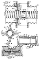
- FIGURE 1 is a perspective view of a coaxial cable assembly embodying the present invention;
- FIG. 2 is an enlarged section taken generally along the line 2-2 in FIGURE 1, with only a portion of the inner conductor assembly shown in section;
- FIG. 3 is an enlarged section taken generally along line 3-3 in FIG.2;
- FIG. 4 is a section taken generally along line 4-4 in FIG. 3;
- FIG. 5 is an enlarged section taken generally along line 5-5 in FIGURE 1;
- FIG. 6 is a section taken generally along line 6-6 in FIG. 5;
- FIG. 7 is a longitudinal section, similar to the central portion of FIG. 5, of a modified embodiment of the invention;
- FIG. 8 is a longitudinal section, similar to the central portion of FIG. 5, of another modified embodiment of the invention.
- Turning now to the drawings and referring first to FIG. 1, a semi-flexible coaxial cable 10 comprises multiple segments 11a, 11b, etc. each having an outer conductor 12a, 12b, etc. and an inner conductor 13a, 13b, etc. The outer conductors of the multiple segments 11 are connected by multiple pairs of flanges 14 and 15, and the left-hand end of the cable is connected by a similar pair of flanges 16 and 17 to a conventional EIA connector 18. Each pair of connecting flanges 14, 15 and 16, 17 is rigidly connected by a series of bolts passed through holes formed at equal intervals around the flanges and attached thereto by nuts threaded onto the bolts (see FIG 2).
- Each individual cable segment has a length which is convenient for packing and shipping in the form of straight lengths, rather than on reels. For example, 12 metres/thirty-nine-foot lengths are convenient for most applications and can be readily packed in standard shipping containers. The inner and
outer conductors 12 and 13 may be packed and shipped separately and assembled in the field, or the inner and outer conductors of each separate segment may be pre-assembled, so that the only field operation required is the joining of the multiple segments. - As can be seen most clearly in FIG. 5, the flanges 14 and 15 used to join adjacent segments are welded to the ends of the outer conductor segments. In the preferred embodiment illustrated in the drawings, each outer conductor segment 12 is corrugated along most of its length, but terminates at each end with a short plain cylindrical section to which one of the flanges 14 or 15 can be easily attached. For example, the flanges can be attached by welding if the outer conductor segments 12 are made of aluminum or by soldering or brazing if the conductor segments are made of copper. The weld seams 19 and 20 preferably extend continuously around the entire circumference of the outer conductors.
- In order to provide a gas seal along the mating surfaces of the two flanges 14 and 15, a pair of O rings 21 and 22 is provided in a pair of recesses 23 and 24 formed in one of the two mating surfaces. If desired, only a single O ring may be used. Air dielectric coaxial cables are often pressurized to control the humidity level within the air space between the inner and outer conductors; the gas seal formed by the O rings 21 and 22 prevents pressurized air from leaking out along the interface between the two flanges. As is conventional with flanges of this type, narrow raised lands are provided around both the inner and outer edges of the mating surfaces of the flanges 14 and 15 to ensure reliable electrical contact between the two flanges when they are drawn together.
- The pair of flanges 16 and 17 which connect the cable segment 11a to the EIA connector 18 are identical to the flanges 14 and 15 just described, except that the flange 16 is welded to a short length of plain cylindrical tubing 25. The other end of this tubing 25 is welded to the flange 26 of the EIA connector 18. The major portion of the EIA connector itself is of conventional design and does not form a part of the present invention.
- Because the illustrative cable can be packed and shipped in straight lengths, the corrugations formed in the outer conductor segments need be only deep enough to provide the desired degree of flexibility and strength for any given application. This is particularly advantageous in the case of cables having relatively large diameters, e.g., 8 to 12 inches, because such cables have normally been corrugated to a depth which provides the degree of flexibility needed to wind such cables on reels for shipment. Most applications, however, do not require such deep corrugations for purposes of flexibility and strength, and the excessively deep corrugations degrade the electrical performance of the cable and compromise its mechanical performance. With the segmented cable of the present invention, superior electrical performance can be achieved by corrugating the outer conductor segments only to the extent necessary to provide the requisite degree of flexibility and strength for any given application. Indeed, it is not even necessary to corrugate the outer conductor segments along their full lengths; if desired, clusters of corrugations can be provided at spaced intervals, as required to provide the desired degree of flexibility and strength.
- In accordance with one aspect of the present invention, the inner conductors of the successive coaxial cable segments 11a, 11b, etc. are rigidly joined to each other to prevent relative movement between the inner conductors of adjacent cable segments. Heretofore, connectors for the inner conductors of coaxial transmission lines have typically included sliding members to allow relative axial movement between the connected conductors as they expand and contract with temperature changes. The temperature of such cables and waveguides increases during operation because of the electrical energy passed therethrough, and the temperature of the inner conductor is usually much higher than that of the outer conductor. Allowing relative axial movement between the inner conductor and its connections reduces stresses due to differential thermal expansion and contraction between the inner and outer conductors, but at the expense of wear on the sliding members and eventual repair and replacement problems. By permitting relative longitudinal movement between the inner and outer conductors, the sliding connections can also lead to the other problems such as displacement of the inner conductor toward one side of the outer conductor when the cable is bent.
- By avoiding sliding movement in the interconnections between adjacent inner conductor segments, the present invention eliminates wear on moving parts, thereby providing a cable having an extended operating life and reduced repair and maintenance problems. In the preferred embodiment illustrated in the drawings, a rigid connection between each pair of adjacent inner conductor segments is effected by telescoping an end portion of one inner conductor segment over the end portion of the adjacent inner conductor segment, with a support sleeve inside the overlapping portions of the conductors, and then fastening a clamp around the outside of the overlapping portions. The clamp is tightened firmly in place by a pair of screws, drawing the overlapping portions of the conductors tightly together against the support sleeve.
- Referring specifically to FIG. 5, the inner conductor 13a of the left-hand cable segment 11a has a plain cylindrical end portion 30which is swaged into a circumferential groove 31 formed in the outer surface of a support sleeve 32 so as to hold the sleeve captive on the cylindrical end portion 30. The extreme end of the conductor 13a is bent inwardly to form a flange 33 which facilitates sliding the two conductors over each other. The adjacent inner conductor 13b also has a plain cylindrical end portion 34 which telescopes over the end portion 30 of the conductor 13a. Several longitudinal slits are formed in the end portion 34 so that it can be compressed tightly against the underlying end portion 30 of the other conductor. The end of the conductor 13b is bent outwardly to form a flange 35 to facilitate sliding end portion 34 over portion 30, and several clamp-locating dimples 36 are formed adjacent the last corrugation of the conductor 13b. A
clamp 37 is mounted in the region between the flange 35 and the clamp locators 36 for drawing the overlapped portions of the conductors 13a and 13b tightly against each other and the support sleeve 32. - The
clamp 37 is illustrated more clearly in FIGS.2 and 3. The main body member 38 of the clamp comprises a single stamped or machined piece of metal which extends around the major portion of the circumference of the inner conductors 13a and 13b. The open ends of the body member 38 are curled outwardly to form recesses for receiving a pair of short cylindrical rods 39 and 40, one of which has two counter-bored holes for receiving the head ends of a pair of screws 41 and 42, and the other of which forms a pair of tapped holes for receiving the threaded shanks of the screws 41 and 42. When the two screws 41 and 42 are tightened, the body member 38 of the clamp is drawn tightly around the overlapping portions of the two inner conductors, thereby clamping them tightly against the inside support sleeve 32. Thus, the two inner conductor segments are rigidly joined to each other, with no sliding fittings. - The connection between the inner conductor segment 13a and the EIA connector 18 is the same as the connection described for the segments 13a and 13b and similar elements in the two connections are identified in the drawings with similar reference numerals, with the addition of a "prime" for the elements in the connection to the EIA connector. The EIA connector 18 is equipped with a special central member 43 which is machined to fit snugly over the plain cylindrical end portion 30′ of the inner conductor segment 13a. As can be seen in FIG. 2, the central member 43 also has several longitudinal slits to permit it to be compressed tightly against the end portion 30′ of the conductor segment 13a. The outer surface of the member 43 forms a clamp-locating circumferential bead 35′ to define a recess for receiving the
clamp 37′. The base of the central member 43 is fastened to the body of the EIA connector 18 by a plurality of machine screws 44. - In accordance with a further aspect of the present invention, a plurality of strain insulators are disposed between the inner and outer conductor segments at a common end of each segment, and each of the insulators has means for interlocking the inner and outer conductor segments to establish and maintain a prescribed relationship between the longitudinal positions of the conductors of each segment. Thus, in the illustrative embodiment of FIG. 5, a
strain insulator 50 is threaded onto the helically corrugated inner conductor 13a. The conductor 13a projects axially beyond the end of the corresponding outer conductor 12a so that the joint between the inner conductor segments is offset in the axial direction from theinsulator 50. As theinsulator 50 is threaded along the inner conductor 13a, it eventually abuts the flange 14. The inside corner of the flange 14 is recessed to mate with the corner of theinsulator 50, so that the outer edges of theinsulator 50 become firmly seated in the flange 14. - The
strain insulator 50 may have a variety of different configurations, but one preferred configuration is illustrated in FIGS. 5 and 6. It can be seen that this particular configuration has acylindrical hub 51 with a threaded inner surface designed to mate with the corrugations of the inner conductor, and fourcross-shaped ribs 52, 53, 54 and 55 extending outwardly at 90° intervals around the circumference of the hub. The four ribs 52-55 terminate in four arcuate sections 56, 57, 58 and 59 which are shaped to fit snugly within the recess formed in the inside corner of the flange 14. That recess extends continuously around the entire circumference of the flange so that theinsulator 50 can be rotated even after it has been seated within the flange. - After the
insulator 50 has been seated in the flange, 14 the mating flange 15 welded to the next outer conductor segment 12b is brought into engagement with the flange 14 and fastened thereto by the plurality of bolts and nuts mentioned previously. As can be seen in FIG. 5, the inside corner of the flange 15 is recessed in the same manner as the inside corner of the flange 14 to mate with the outside edge of theinsulator 50. Thus, when the two flanges 14 and 15 have been bolted together, theinsulator 50 is securely captured between the two flanges. Thestrain insulator 50 then serves to hold the inner and outer conductors in the desired positions relative to each other, and also to transmit stresses due to differential thermal expansion and contraction between the inner and outer conductor segments. In this connection, it should be noted that the ribs 52-55 of theinsulator 50 must be strong enough to withstand such stresses. - Locking the corrugated inner conductor to the outer conductor at regular intervals along the length of the cable holds the flexible inner and outer conductors in fixed longitudinal positions relative to each other. This offers several advantages. For example, when the cable is bent the interlocking of the inner and outer conductors substantially prevents the inner conductor from being displaced toward one side of the outer conductor in the bend; for such displacement to occur to any significant degree the inner conductor must be free to move longitudinally within the outer conductor, and the interlocking action of the strain insulators effectively prevents such longitudinal movement. The same interlocking action resists relative longitudinal movement between the inner and outer conductors due to external loads on the outer conductor, such as axial forces applied to the outer conductor by the structure used to support the cable assembly.
- The combination of the corrugated inner conductor segments and the interlocking of the inner and outer conductors of each cable segment also eliminates the need for any sliding members in the connections between adjacent segments, thereby eliminating the attendant disadvantages of such sliding members. Any stresses produced by differential thermal expansion and contraction between the inner and outer conductor segments are transmitted through the
insulators 50 to the flanges 14 and 15, and then on to the supporting structure for the cable assembly. Similarly, any loads applied to only the inner conductor or only the outer conductor are transmitted via the strain insulators to the other conductor. - According to a further important feature of this invention, the
strain insulators 50 which interlock the inner and outer conductor segments are also used to controllably pre-stress the inner conductor segments. For example, pre-tensioning the inner conductor segments reduces deformation of the inner conductor segments due to differential thermal expansion of the inner and outer conductors under operating conditions. By continuing to turn theinsulator 50 after it has been seated in the flange 14 welded to the outer conductor 12a, theinsulator 50 can be used to expand the corrugated inner conductor 13a in the axial direction, thereby applying a controllable degree of pre-tensioning to the inner conductor segment. That is, the threaded connection between theinsulator 50 and the inner conductor segment 13a draws the inner conductor through the insulator, thereby controlling the length of inner conductor that projects beyond the insulator for attachment to the adjacent inner conductor segment 13b. Consequently, theinsulator 50 permits the projecting end portion of the inner conductor segment 13a to be precisely located, while at the same time controlling the tensile load on the inner conductor. - The strain insulators 50 may also be used to pre-compress, rather than pre-tension, the inner conductor segments. This may be accomplished, for example, by rotating the strain insulator in a direction that would cause the insulator to move away from the insulator 14 while blocking such movement with the flange 15; the inner conductor segment 13a will then be drawn through the insulator in the reverse direction, i.e., shortening the length of inner conductor that projects beyond the insulator and compressing the major length of the inner conductor segment.
- As yet another feature of this invention, the inner conductor joints are offset in the axial direction from the insulators by a distance which is only a fraction of a wavelength, preferably less than one-quarter wavelength, and the offset joints are shaped and dimensioned to compensate for the adverse effect of the insulators on the VSWR of the cable assembly. Because the
insulators 50 have a dielectric constant greater than that of air, the insulators tend to cause an undesirable increase in the VSWR of the cable assembly. To compensate for the effect of the insulators and thus minimize the VSWR increase, air dielectric coaxial cables have typically been provided with inner conductors which are indented at the inner surface of the insulators, and/or with outer conductors which are bulged outwardly at the outer surfaces of the insulators. In the present invention, however, it is preferred to permit theinsulators 50 to be positioned at different locations along the length of the inner conductor, so as to permit the inner conductor segments to be pre-tensioned to the desired level and to permit precise positioning of the projecting ends of the inner conductor segments. - Accordingly, the joint between adjacent inner conductor segments is designed to provide a compensating indentation in the outer surface of the inner conductor, and is located close enough to the insulator (a small fraction of a wavelength) to provide the desired VSWR-compensating effect. The joint can, however, still be located far enough away from the final position of the insulator to provide ready access to the joint, beyond the end of the corresponding outer conductor segment, for initial installation and subsequent repair of replacement. Furthermore, the fact that the VSWR compensation is provided by a rigid structure rather than a structure that includes sliding members renders the VSWR compensation highly stable. The joints between the inner conductor segments can also degrade the VSWR slightly, but this effect can also be compensated by the size and shape of the joints themselves.
- By virtue of the axial offset between the connections of the inner and outer conductor segments, the ends of the inner conductor segments are readily accessible for joining successive segments. During initial installation, each pair of inner conductor segments is connected before the corresponding pair of outer conductor segments. Then the next outer conductor segment is telescoped over the completed inner conductor joint so that the outer conductor flanges can be bolted together.
- Referring particularly to FIG. 5, it can be seen that the
clamp 37 has a smaller outside diameter (except for the fastening elements on the clamp) than the crests of the corrugations of the main body portions of the inner conductor segments 13a and 13b. Thus, the joint between the inner conductor segments has a smaller effective diameter than that of the corrugated portions of the inner conductor segments, thereby providing the desired VSWR compensation. The effect of this inner conductor joint on the VSWR is determined not only by the outside diameter of the joint assembly, but also by its longitudinal dimension. In coaxial transmission lines, the electric currents flow in the outside surface of the inner conductor and the inside surfaces of the outer conductor, and thus it is the outside surface of the joint between the inner conductor segments which primarily determines the effect of the joint on the VSWR of the cable. - The smaller diameter of the inner conductor joints causes the temperature of those particular portions of the inner conductor assembly to increase more than the corrugated portions of the inner conductor during operation. Consequently, a further advantage of the axial offset of the joints from the strain insulators is that heat can be more readily dissipated by radiation and convection from the joints.
- As an alternative to the use of indented regions in the inner conductor to compensate for the VSWR degradation caused by the strain insulators and the inner conductor joints, localized outward bulges in the outer conductor segments can be used to provide the same type of compensation. At least one such bulge should be provided for each strain insulator, preferably offset from the strain insulator by less than a quarter wavelength.
- Alternative inner conductor joint assemblies are illustrated in FIGS. 7 and 8. In the particular embodiment illustrated in FIG. 7, two machined connecting
elements 60 and 61 are threaded into the inner conductor segments 12a and 12b, respectively. The male element 60 forms an integral support sleeve which extends inside the end portion of thefemale element 61 and is soldered in place. The end portion of the female connectingelement 61, is similar tothe end portion of the inner conductor segment 13b described above; i.e., a recess for receiving theclamp 37 is formed by an outwardly extending flange 62 and a plurality of clamp-locating dimples 63 spaced around the circumference of the element. When theclamp 37 is tightened, it draws the slit end portion of thefemale element 61 firmly against the outside surface of the male element 60. This particular connecting arrangement eliminates the need for the swaging operation, because both the connectingelements 60 and 61 are simply threaded and soldered into the respective connectors. - In the modified embodiment illustrated in FIG. 8, a pair of machined brass connecting elements 70 and 71 are again threaded and soldered into the inner conductor segments 12a and 12b, respectively. In this design, the elements 70 and 71 have threaded bores for receiving oppositely threaded shanks 72 and 73 extending in opposite directions from a central hexagonal head 74. The head 74 is captured inside a sliding sleeve 75 provided with a
hole 76 for receiving a tool to rotate the sleeve 75. As the sleeve 75 is rotated, it also rotates the hexagonal head 74 captured therein, thereby threading the two shanks 72 and 73 into the respective connecting elements 70 and 71 and drawing those elements toward each other. To ensure good electrical contact between the sleeve 75 and the brass elements 70 and 71,circumferential recesses - While the invention has been described thus far with particular reference to the use of a segmented inner conductor, this invention is also applicable to a cable assembly which has continuous corrugated inner conductor and a segmented outer conductor. The continuous inner conductor can be packaged and shipped separately from the outer conductor segments, and can be more readily wound on a reel without excessively deep corrugations because of its smaller diameter. With a continuous inner conductor, the strain insulators are preferably made in two or more pieces which can be fit onto the inner conductor at the desired location and then fastened together. The strain insulators can still be used to pre-stress the continuous inner conductor.
- The corrugations in the inner conductor may also be annular rather than helical. Annular corrugations do not interconnect with each other, i.e., each corrugation forms a closed circle. Consequently, it is preferred to use split strain insulators with annularly corrugated inner conductors, so that the two halves of each insulator can be applied to the inner conductor from opposite sides and then fastened together to clamp them onto the conductor. Such an insulator requires a supplementary device such as a threaded sleeve if adjustable location or pre-stressing is desired.
Claims (14)
- A coaxial cable assembly comprising a coaxial cable having an outer conductor (12) and an inner conductor (13), at least said outer conductor (12) comprising multiple segments (12a,12b), joining means (14,15) on each end of each segment for mechanically and electrically joining adjacent segments to each other, said joining means rigidly joining adjacent segments of the assembly to prevent relative longitudinal movement between adjacent segments, multiple strain insulators (50) each of which is located at an end of a segment (12a,12b) and extends to engage the inner conductor (13) of the assembly, the strain insulators (50) establishing and maintaining a prescribed fixed relationship between the longitudinal positions of the inner and outer conductors (12,13), wherein prior to being assembled into the assembly each segment (12a,12b) has a length which can be packed and shipped in straight lengths, and each segment (12a,12b) is movable in the longitudinal direction relative to said inner conductor (13) so that said outer conductor segment (12a,12b) can be telescoped over said inner conductor (13), characterised in that said inner conductor (13) is corrugated, and in that the entire length of said inner conductor (13) between adjacent strain insulators (50) is maintained in a fixed longitudinal spatial relationship to said outer conductor (12) under operating conditions.
- The coaxial cable assembly as claimed in claim 1, characterised in that the segments (12a,12b) of the outer conductor (12) are corrugated.
- The coaxial cable assembly of claim 1 or claim 2 wherein said strain insulators (50) are threaded onto the corrugated inner conductor (13), characterised in that said insulators (50) are peripherally clamped between adjacent segments (12a,12b) of said outer conductor (12) by said joining means.
- The coaxial cable assembly of claim 1 characterised in that the inner conductor (13) is formed of adjacent corrugated segments (13a,13b) rigidly joined to each other to prevent relative movement therebetween.
- The coaxial cable assembly of claim 4 wherein the means for joining said inner conductor segments (13a,13b) is detachable, and characterised in that each inner conductor segment (13a,13b) protrudes in the axial direction beyond one end of the corresponding outer conductor segment (12a,12b) to provide ready access to the end of the inner conductor segment (13a) for joining it to an adjacent inner conductor segment (13b).
- The coaxial cable assembly of claim 4 or claim 5 characterised in that the inner conductor joints form indentations in the outer surface of the assembled inner conductor (13).
- The coaxial cable assembly as claimed in any preceding claim, characterised in that said strain insulators (50) pre-stress the inner (13) conductor in the longitudinal direction relative to the outer conductor (12) and hold the inner conductor (13) in the stressed condition so as to reduce deformation of the inner conductor (13) due to differential thermal expansion of the inner (13) and outer (12) conductors under operating conditions.
- The coaxial cable assembly of claim 7 wherein said strain insulators (50) are threaded onto the corrugated inner conductor (13), characterised in that means are provided in the assembly for limiting threading movement of each of said insulators (50) along said inner conductor (13) whereby continued rotational movement of said insulators (50) about said inner conductor (13) exerts a tensile load on said inner conductor (13) to pre-tension the inner conductor (13).
- The coaxial cable assembly of claim 8, characterised in that said limiting means comprises a shoulder formed on the joining means (14,15) attached to the end of each outer conductor segment (12a,12b) the shoulder being shaped to receive the outer portion (56,57,58,59) of said insulator (50) as the insulator (50) is advanced longitudinally over said inner conductor (13) and blocking any further advancing movement of said insulator (50).
- The coaxial cable assembly of claim 1 characterised in that said inner conductor (13) is a continuous conductor.
- The coaxial cable assembly as claimed in claim 1, characterised in that portions of at least one of said inner (13) and outer (12) conductors have means shaped and dimensioned to compensate for the adverse effect of said insulators (50) on the VSWR of the cable assembly (10), said VSWR-compensating portions being offset in the axial direction from said insulators (50).
- The coaxial cable assembly of claim 11, characterised in that said inner conductor (13) comprises a plurality of longitudinal segments (13a,13b) which are rigidly joined to each other, and said VSWR-compensating portions compensate for any adverse effect of the joints between said segments (13a,13b) on the VSWR of the cable assembly (10).
- The coaxial cable assembly of claim 11 characterised in that said VSWR-compensating portions include outward bulges in said outer conductor (12), at least one of said bulges being associated with each of said strain insulators (50) and longitudinally offset from the strain insulator (50).
- A method of making and installing a coaxial cable transmission line, said method being
fabricating an outer conductor in multiple segments having a length which can be packed and shipped in straight lengths rather than on reels,
fabricating a corrugated inner conductor which is either a single continuous unit or multiple segments which can be rigidly joined to prevent relative longitudinal movement between adjacent segments,
packing and shipping at least the outer conductor segments in straight lengths,
installing the cable by telecoping the outer conductor segments over the inner conductor with multiple strain insulators, located at ends of outer conductor segments, which interlock the inner and outer conductors to establish and maintain a fixed relationship between longitudinal positions of said inner and outer conductors such that the entire length of said inner conductor between adjacent strain insulators is maintained in a fixed longitudinal spatial relationship to said outer conductor under operating conditions, and
rigidly joining adjacent outer conductor segments to prevent relative longitudinal movement between adjacent segments whereby both the inner and outer conductors are individually mechanically united along their entire lengths under operating conditions of the transmission line.
Applications Claiming Priority (2)
| Application Number | Priority Date | Filing Date | Title |
|---|---|---|---|
| US07/031,098 US4831346A (en) | 1987-03-26 | 1987-03-26 | Segmented coaxial transmission line |
| US31098 | 1998-02-26 |
Publications (3)
| Publication Number | Publication Date |
|---|---|
| EP0284402A2 EP0284402A2 (en) | 1988-09-28 |
| EP0284402A3 EP0284402A3 (en) | 1989-08-09 |
| EP0284402B1 true EP0284402B1 (en) | 1995-01-11 |
Family
ID=21857650
Family Applications (1)
| Application Number | Title | Priority Date | Filing Date |
|---|---|---|---|
| EP88302648A Expired - Lifetime EP0284402B1 (en) | 1987-03-26 | 1988-03-25 | Segmented coaxial transmission line |
Country Status (4)
| Country | Link |
|---|---|
| US (1) | US4831346A (en) |
| EP (1) | EP0284402B1 (en) |
| JP (1) | JPS63257118A (en) |
| DE (1) | DE3852707T2 (en) |
Cited By (3)
| Publication number | Priority date | Publication date | Assignee | Title |
|---|---|---|---|---|
| RU2338279C2 (en) * | 2006-08-04 | 2008-11-10 | Закрытое Акционерное Общество "Самара-Импэкс-Кабель" | Electric communication cable |
| US11359473B2 (en) | 2016-04-13 | 2022-06-14 | Acceleware Ltd. | Apparatus and methods for electromagnetic heating of hydrocarbon formations |
| US12176594B2 (en) | 2021-05-04 | 2024-12-24 | Acceleware Ltd. | Apparatus and methods for providing a coaxial transmission line |
Families Citing this family (175)
| Publication number | Priority date | Publication date | Assignee | Title |
|---|---|---|---|---|
| US5850056A (en) * | 1996-04-22 | 1998-12-15 | Andrew Corporation | Grounding kit for a transmission line cable including a clip, a bail and a housing |
| US7054795B1 (en) | 1999-05-26 | 2006-05-30 | Myat Inc. | Method for selecting optimized lengths of a segmented transmission line and a transmission line resulting therefrom |
| EP1148592A1 (en) | 2000-04-17 | 2001-10-24 | Cabel-Con A/S | Connector for a coaxial cable with corrugated outer conductor |
| GB0215659D0 (en) * | 2002-07-06 | 2002-08-14 | Weatherford Lamb | Formed tubulars |
| US6712644B1 (en) * | 2003-05-28 | 2004-03-30 | Spx Corporation | Coaxial line section assembly and method with VSWR compensation |
| US6972648B2 (en) * | 2003-07-24 | 2005-12-06 | Spx Corporation | Broadband coaxial transmission line using uniformly distributed uniform mismatches |
| EP2902552B1 (en) | 2006-03-30 | 2020-06-17 | Esco Group LLC | Wear member for excavating equipment |
| US20070271074A1 (en) * | 2006-05-16 | 2007-11-22 | Electronics Research, Inc. | Multi-section transmission line |
| AU2010310849B2 (en) * | 2009-10-19 | 2013-05-02 | Greatpoint Energy, Inc. | Integrated enhanced oil recovery process |
| DE102010045780A1 (en) * | 2010-09-17 | 2012-03-22 | Rohde & Schwarz Gmbh & Co. Kg | Calibration unit for a measuring device |
| CN102441855A (en) * | 2010-09-30 | 2012-05-09 | 河南省电力公司焦作供电公司 | A vertical flange mounting hole coaxiality fixture |
| US10009065B2 (en) | 2012-12-05 | 2018-06-26 | At&T Intellectual Property I, L.P. | Backhaul link for distributed antenna system |
| US9113347B2 (en) | 2012-12-05 | 2015-08-18 | At&T Intellectual Property I, Lp | Backhaul link for distributed antenna system |
| US9999038B2 (en) | 2013-05-31 | 2018-06-12 | At&T Intellectual Property I, L.P. | Remote distributed antenna system |
| US9525524B2 (en) | 2013-05-31 | 2016-12-20 | At&T Intellectual Property I, L.P. | Remote distributed antenna system |
| US8897697B1 (en) | 2013-11-06 | 2014-11-25 | At&T Intellectual Property I, Lp | Millimeter-wave surface-wave communications |
| US9209902B2 (en) | 2013-12-10 | 2015-12-08 | At&T Intellectual Property I, L.P. | Quasi-optical coupler |
| US9692101B2 (en) | 2014-08-26 | 2017-06-27 | At&T Intellectual Property I, L.P. | Guided wave couplers for coupling electromagnetic waves between a waveguide surface and a surface of a wire |
| US9768833B2 (en) | 2014-09-15 | 2017-09-19 | At&T Intellectual Property I, L.P. | Method and apparatus for sensing a condition in a transmission medium of electromagnetic waves |
| US10063280B2 (en) | 2014-09-17 | 2018-08-28 | At&T Intellectual Property I, L.P. | Monitoring and mitigating conditions in a communication network |
| US9628854B2 (en) | 2014-09-29 | 2017-04-18 | At&T Intellectual Property I, L.P. | Method and apparatus for distributing content in a communication network |
| US9615269B2 (en) | 2014-10-02 | 2017-04-04 | At&T Intellectual Property I, L.P. | Method and apparatus that provides fault tolerance in a communication network |
| US9685992B2 (en) | 2014-10-03 | 2017-06-20 | At&T Intellectual Property I, L.P. | Circuit panel network and methods thereof |
| US9503189B2 (en) | 2014-10-10 | 2016-11-22 | At&T Intellectual Property I, L.P. | Method and apparatus for arranging communication sessions in a communication system |
| US9973299B2 (en) | 2014-10-14 | 2018-05-15 | At&T Intellectual Property I, L.P. | Method and apparatus for adjusting a mode of communication in a communication network |
| US9762289B2 (en) | 2014-10-14 | 2017-09-12 | At&T Intellectual Property I, L.P. | Method and apparatus for transmitting or receiving signals in a transportation system |
| US9780834B2 (en) | 2014-10-21 | 2017-10-03 | At&T Intellectual Property I, L.P. | Method and apparatus for transmitting electromagnetic waves |
| US9653770B2 (en) | 2014-10-21 | 2017-05-16 | At&T Intellectual Property I, L.P. | Guided wave coupler, coupling module and methods for use therewith |
| US9520945B2 (en) | 2014-10-21 | 2016-12-13 | At&T Intellectual Property I, L.P. | Apparatus for providing communication services and methods thereof |
| US9577306B2 (en) | 2014-10-21 | 2017-02-21 | At&T Intellectual Property I, L.P. | Guided-wave transmission device and methods for use therewith |
| US9312919B1 (en) | 2014-10-21 | 2016-04-12 | At&T Intellectual Property I, Lp | Transmission device with impairment compensation and methods for use therewith |
| US9769020B2 (en) | 2014-10-21 | 2017-09-19 | At&T Intellectual Property I, L.P. | Method and apparatus for responding to events affecting communications in a communication network |
| US9564947B2 (en) | 2014-10-21 | 2017-02-07 | At&T Intellectual Property I, L.P. | Guided-wave transmission device with diversity and methods for use therewith |
| US9627768B2 (en) | 2014-10-21 | 2017-04-18 | At&T Intellectual Property I, L.P. | Guided-wave transmission device with non-fundamental mode propagation and methods for use therewith |
| US10340573B2 (en) | 2016-10-26 | 2019-07-02 | At&T Intellectual Property I, L.P. | Launcher with cylindrical coupling device and methods for use therewith |
| US9680670B2 (en) | 2014-11-20 | 2017-06-13 | At&T Intellectual Property I, L.P. | Transmission device with channel equalization and control and methods for use therewith |
| US9997819B2 (en) | 2015-06-09 | 2018-06-12 | At&T Intellectual Property I, L.P. | Transmission medium and method for facilitating propagation of electromagnetic waves via a core |
| US9461706B1 (en) | 2015-07-31 | 2016-10-04 | At&T Intellectual Property I, Lp | Method and apparatus for exchanging communication signals |
| US9742462B2 (en) | 2014-12-04 | 2017-08-22 | At&T Intellectual Property I, L.P. | Transmission medium and communication interfaces and methods for use therewith |
| US10243784B2 (en) | 2014-11-20 | 2019-03-26 | At&T Intellectual Property I, L.P. | System for generating topology information and methods thereof |
| US9544006B2 (en) | 2014-11-20 | 2017-01-10 | At&T Intellectual Property I, L.P. | Transmission device with mode division multiplexing and methods for use therewith |
| US9800327B2 (en) | 2014-11-20 | 2017-10-24 | At&T Intellectual Property I, L.P. | Apparatus for controlling operations of a communication device and methods thereof |
| US9954287B2 (en) | 2014-11-20 | 2018-04-24 | At&T Intellectual Property I, L.P. | Apparatus for converting wireless signals and electromagnetic waves and methods thereof |
| US10009067B2 (en) | 2014-12-04 | 2018-06-26 | At&T Intellectual Property I, L.P. | Method and apparatus for configuring a communication interface |
| US9654173B2 (en) | 2014-11-20 | 2017-05-16 | At&T Intellectual Property I, L.P. | Apparatus for powering a communication device and methods thereof |
| US10144036B2 (en) | 2015-01-30 | 2018-12-04 | At&T Intellectual Property I, L.P. | Method and apparatus for mitigating interference affecting a propagation of electromagnetic waves guided by a transmission medium |
| US9876570B2 (en) | 2015-02-20 | 2018-01-23 | At&T Intellectual Property I, Lp | Guided-wave transmission device with non-fundamental mode propagation and methods for use therewith |
| US9749013B2 (en) | 2015-03-17 | 2017-08-29 | At&T Intellectual Property I, L.P. | Method and apparatus for reducing attenuation of electromagnetic waves guided by a transmission medium |
| US10224981B2 (en) | 2015-04-24 | 2019-03-05 | At&T Intellectual Property I, Lp | Passive electrical coupling device and methods for use therewith |
| US9705561B2 (en) | 2015-04-24 | 2017-07-11 | At&T Intellectual Property I, L.P. | Directional coupling device and methods for use therewith |
| US9948354B2 (en) | 2015-04-28 | 2018-04-17 | At&T Intellectual Property I, L.P. | Magnetic coupling device with reflective plate and methods for use therewith |
| US9793954B2 (en) | 2015-04-28 | 2017-10-17 | At&T Intellectual Property I, L.P. | Magnetic coupling device and methods for use therewith |
| US9871282B2 (en) | 2015-05-14 | 2018-01-16 | At&T Intellectual Property I, L.P. | At least one transmission medium having a dielectric surface that is covered at least in part by a second dielectric |
| US9748626B2 (en) | 2015-05-14 | 2017-08-29 | At&T Intellectual Property I, L.P. | Plurality of cables having different cross-sectional shapes which are bundled together to form a transmission medium |
| US9490869B1 (en) | 2015-05-14 | 2016-11-08 | At&T Intellectual Property I, L.P. | Transmission medium having multiple cores and methods for use therewith |
| US10679767B2 (en) | 2015-05-15 | 2020-06-09 | At&T Intellectual Property I, L.P. | Transmission medium having a conductive material and methods for use therewith |
| US10650940B2 (en) | 2015-05-15 | 2020-05-12 | At&T Intellectual Property I, L.P. | Transmission medium having a conductive material and methods for use therewith |
| US9917341B2 (en) | 2015-05-27 | 2018-03-13 | At&T Intellectual Property I, L.P. | Apparatus and method for launching electromagnetic waves and for modifying radial dimensions of the propagating electromagnetic waves |
| US10348391B2 (en) | 2015-06-03 | 2019-07-09 | At&T Intellectual Property I, L.P. | Client node device with frequency conversion and methods for use therewith |
| US10103801B2 (en) | 2015-06-03 | 2018-10-16 | At&T Intellectual Property I, L.P. | Host node device and methods for use therewith |
| US10154493B2 (en) | 2015-06-03 | 2018-12-11 | At&T Intellectual Property I, L.P. | Network termination and methods for use therewith |
| US9912381B2 (en) | 2015-06-03 | 2018-03-06 | At&T Intellectual Property I, Lp | Network termination and methods for use therewith |
| US10812174B2 (en) | 2015-06-03 | 2020-10-20 | At&T Intellectual Property I, L.P. | Client node device and methods for use therewith |
| US9866309B2 (en) | 2015-06-03 | 2018-01-09 | At&T Intellectual Property I, Lp | Host node device and methods for use therewith |
| US9913139B2 (en) | 2015-06-09 | 2018-03-06 | At&T Intellectual Property I, L.P. | Signal fingerprinting for authentication of communicating devices |
| US9608692B2 (en) | 2015-06-11 | 2017-03-28 | At&T Intellectual Property I, L.P. | Repeater and methods for use therewith |
| US10142086B2 (en) | 2015-06-11 | 2018-11-27 | At&T Intellectual Property I, L.P. | Repeater and methods for use therewith |
| US9820146B2 (en) | 2015-06-12 | 2017-11-14 | At&T Intellectual Property I, L.P. | Method and apparatus for authentication and identity management of communicating devices |
| US9667317B2 (en) | 2015-06-15 | 2017-05-30 | At&T Intellectual Property I, L.P. | Method and apparatus for providing security using network traffic adjustments |
| US9509415B1 (en) | 2015-06-25 | 2016-11-29 | At&T Intellectual Property I, L.P. | Methods and apparatus for inducing a fundamental wave mode on a transmission medium |
| US9865911B2 (en) | 2015-06-25 | 2018-01-09 | At&T Intellectual Property I, L.P. | Waveguide system for slot radiating first electromagnetic waves that are combined into a non-fundamental wave mode second electromagnetic wave on a transmission medium |
| US9640850B2 (en) | 2015-06-25 | 2017-05-02 | At&T Intellectual Property I, L.P. | Methods and apparatus for inducing a non-fundamental wave mode on a transmission medium |
| US10341142B2 (en) | 2015-07-14 | 2019-07-02 | At&T Intellectual Property I, L.P. | Apparatus and methods for generating non-interfering electromagnetic waves on an uninsulated conductor |
| US9722318B2 (en) | 2015-07-14 | 2017-08-01 | At&T Intellectual Property I, L.P. | Method and apparatus for coupling an antenna to a device |
| US9853342B2 (en) | 2015-07-14 | 2017-12-26 | At&T Intellectual Property I, L.P. | Dielectric transmission medium connector and methods for use therewith |
| US10205655B2 (en) | 2015-07-14 | 2019-02-12 | At&T Intellectual Property I, L.P. | Apparatus and methods for communicating utilizing an antenna array and multiple communication paths |
| US10044409B2 (en) | 2015-07-14 | 2018-08-07 | At&T Intellectual Property I, L.P. | Transmission medium and methods for use therewith |
| US9882257B2 (en) | 2015-07-14 | 2018-01-30 | At&T Intellectual Property I, L.P. | Method and apparatus for launching a wave mode that mitigates interference |
| US9847566B2 (en) | 2015-07-14 | 2017-12-19 | At&T Intellectual Property I, L.P. | Method and apparatus for adjusting a field of a signal to mitigate interference |
| US10148016B2 (en) | 2015-07-14 | 2018-12-04 | At&T Intellectual Property I, L.P. | Apparatus and methods for communicating utilizing an antenna array |
| US10033108B2 (en) | 2015-07-14 | 2018-07-24 | At&T Intellectual Property I, L.P. | Apparatus and methods for generating an electromagnetic wave having a wave mode that mitigates interference |
| US10033107B2 (en) | 2015-07-14 | 2018-07-24 | At&T Intellectual Property I, L.P. | Method and apparatus for coupling an antenna to a device |
| US9628116B2 (en) | 2015-07-14 | 2017-04-18 | At&T Intellectual Property I, L.P. | Apparatus and methods for transmitting wireless signals |
| US9836957B2 (en) | 2015-07-14 | 2017-12-05 | At&T Intellectual Property I, L.P. | Method and apparatus for communicating with premises equipment |
| US10320586B2 (en) | 2015-07-14 | 2019-06-11 | At&T Intellectual Property I, L.P. | Apparatus and methods for generating non-interfering electromagnetic waves on an insulated transmission medium |
| US10170840B2 (en) | 2015-07-14 | 2019-01-01 | At&T Intellectual Property I, L.P. | Apparatus and methods for sending or receiving electromagnetic signals |
| US10090606B2 (en) | 2015-07-15 | 2018-10-02 | At&T Intellectual Property I, L.P. | Antenna system with dielectric array and methods for use therewith |
| US9608740B2 (en) | 2015-07-15 | 2017-03-28 | At&T Intellectual Property I, L.P. | Method and apparatus for launching a wave mode that mitigates interference |
| US9793951B2 (en) | 2015-07-15 | 2017-10-17 | At&T Intellectual Property I, L.P. | Method and apparatus for launching a wave mode that mitigates interference |
| US9912027B2 (en) | 2015-07-23 | 2018-03-06 | At&T Intellectual Property I, L.P. | Method and apparatus for exchanging communication signals |
| US10784670B2 (en) | 2015-07-23 | 2020-09-22 | At&T Intellectual Property I, L.P. | Antenna support for aligning an antenna |
| US9749053B2 (en) | 2015-07-23 | 2017-08-29 | At&T Intellectual Property I, L.P. | Node device, repeater and methods for use therewith |
| US9871283B2 (en) | 2015-07-23 | 2018-01-16 | At&T Intellectual Property I, Lp | Transmission medium having a dielectric core comprised of plural members connected by a ball and socket configuration |
| US9948333B2 (en) | 2015-07-23 | 2018-04-17 | At&T Intellectual Property I, L.P. | Method and apparatus for wireless communications to mitigate interference |
| US10020587B2 (en) | 2015-07-31 | 2018-07-10 | At&T Intellectual Property I, L.P. | Radial antenna and methods for use therewith |
| US9735833B2 (en) | 2015-07-31 | 2017-08-15 | At&T Intellectual Property I, L.P. | Method and apparatus for communications management in a neighborhood network |
| US9967173B2 (en) | 2015-07-31 | 2018-05-08 | At&T Intellectual Property I, L.P. | Method and apparatus for authentication and identity management of communicating devices |
| US9904535B2 (en) | 2015-09-14 | 2018-02-27 | At&T Intellectual Property I, L.P. | Method and apparatus for distributing software |
| US9705571B2 (en) | 2015-09-16 | 2017-07-11 | At&T Intellectual Property I, L.P. | Method and apparatus for use with a radio distributed antenna system |
| US10009901B2 (en) | 2015-09-16 | 2018-06-26 | At&T Intellectual Property I, L.P. | Method, apparatus, and computer-readable storage medium for managing utilization of wireless resources between base stations |
| US10136434B2 (en) | 2015-09-16 | 2018-11-20 | At&T Intellectual Property I, L.P. | Method and apparatus for use with a radio distributed antenna system having an ultra-wideband control channel |
| US10009063B2 (en) | 2015-09-16 | 2018-06-26 | At&T Intellectual Property I, L.P. | Method and apparatus for use with a radio distributed antenna system having an out-of-band reference signal |
| US10051629B2 (en) | 2015-09-16 | 2018-08-14 | At&T Intellectual Property I, L.P. | Method and apparatus for use with a radio distributed antenna system having an in-band reference signal |
| US10079661B2 (en) | 2015-09-16 | 2018-09-18 | At&T Intellectual Property I, L.P. | Method and apparatus for use with a radio distributed antenna system having a clock reference |
| US9769128B2 (en) | 2015-09-28 | 2017-09-19 | At&T Intellectual Property I, L.P. | Method and apparatus for encryption of communications over a network |
| US9729197B2 (en) | 2015-10-01 | 2017-08-08 | At&T Intellectual Property I, L.P. | Method and apparatus for communicating network management traffic over a network |
| US10074890B2 (en) | 2015-10-02 | 2018-09-11 | At&T Intellectual Property I, L.P. | Communication device and antenna with integrated light assembly |
| US9882277B2 (en) | 2015-10-02 | 2018-01-30 | At&T Intellectual Property I, Lp | Communication device and antenna assembly with actuated gimbal mount |
| US9876264B2 (en) | 2015-10-02 | 2018-01-23 | At&T Intellectual Property I, Lp | Communication system, guided wave switch and methods for use therewith |
| US10665942B2 (en) | 2015-10-16 | 2020-05-26 | At&T Intellectual Property I, L.P. | Method and apparatus for adjusting wireless communications |
| US10355367B2 (en) | 2015-10-16 | 2019-07-16 | At&T Intellectual Property I, L.P. | Antenna structure for exchanging wireless signals |
| US10051483B2 (en) | 2015-10-16 | 2018-08-14 | At&T Intellectual Property I, L.P. | Method and apparatus for directing wireless signals |
| US9865910B2 (en) * | 2016-04-14 | 2018-01-09 | Electronics Research, Inc. | Optimized coaxial transmission line and method for overcoming flange reflections |
| US9912419B1 (en) | 2016-08-24 | 2018-03-06 | At&T Intellectual Property I, L.P. | Method and apparatus for managing a fault in a distributed antenna system |
| US9860075B1 (en) | 2016-08-26 | 2018-01-02 | At&T Intellectual Property I, L.P. | Method and communication node for broadband distribution |
| US10291311B2 (en) | 2016-09-09 | 2019-05-14 | At&T Intellectual Property I, L.P. | Method and apparatus for mitigating a fault in a distributed antenna system |
| US11032819B2 (en) | 2016-09-15 | 2021-06-08 | At&T Intellectual Property I, L.P. | Method and apparatus for use with a radio distributed antenna system having a control channel reference signal |
| US10340600B2 (en) | 2016-10-18 | 2019-07-02 | At&T Intellectual Property I, L.P. | Apparatus and methods for launching guided waves via plural waveguide systems |
| US10135147B2 (en) | 2016-10-18 | 2018-11-20 | At&T Intellectual Property I, L.P. | Apparatus and methods for launching guided waves via an antenna |
| US10135146B2 (en) | 2016-10-18 | 2018-11-20 | At&T Intellectual Property I, L.P. | Apparatus and methods for launching guided waves via circuits |
| US10374316B2 (en) | 2016-10-21 | 2019-08-06 | At&T Intellectual Property I, L.P. | System and dielectric antenna with non-uniform dielectric |
| US9991580B2 (en) | 2016-10-21 | 2018-06-05 | At&T Intellectual Property I, L.P. | Launcher and coupling system for guided wave mode cancellation |
| US9876605B1 (en) | 2016-10-21 | 2018-01-23 | At&T Intellectual Property I, L.P. | Launcher and coupling system to support desired guided wave mode |
| US10811767B2 (en) | 2016-10-21 | 2020-10-20 | At&T Intellectual Property I, L.P. | System and dielectric antenna with convex dielectric radome |
| US10312567B2 (en) | 2016-10-26 | 2019-06-04 | At&T Intellectual Property I, L.P. | Launcher with planar strip antenna and methods for use therewith |
| US10291334B2 (en) | 2016-11-03 | 2019-05-14 | At&T Intellectual Property I, L.P. | System for detecting a fault in a communication system |
| US10498044B2 (en) | 2016-11-03 | 2019-12-03 | At&T Intellectual Property I, L.P. | Apparatus for configuring a surface of an antenna |
| US10224634B2 (en) | 2016-11-03 | 2019-03-05 | At&T Intellectual Property I, L.P. | Methods and apparatus for adjusting an operational characteristic of an antenna |
| US10225025B2 (en) | 2016-11-03 | 2019-03-05 | At&T Intellectual Property I, L.P. | Method and apparatus for detecting a fault in a communication system |
| US10340601B2 (en) | 2016-11-23 | 2019-07-02 | At&T Intellectual Property I, L.P. | Multi-antenna system and methods for use therewith |
| US10178445B2 (en) | 2016-11-23 | 2019-01-08 | At&T Intellectual Property I, L.P. | Methods, devices, and systems for load balancing between a plurality of waveguides |
| US10535928B2 (en) | 2016-11-23 | 2020-01-14 | At&T Intellectual Property I, L.P. | Antenna system and methods for use therewith |
| US10340603B2 (en) | 2016-11-23 | 2019-07-02 | At&T Intellectual Property I, L.P. | Antenna system having shielded structural configurations for assembly |
| US10090594B2 (en) | 2016-11-23 | 2018-10-02 | At&T Intellectual Property I, L.P. | Antenna system having structural configurations for assembly |
| US10305190B2 (en) | 2016-12-01 | 2019-05-28 | At&T Intellectual Property I, L.P. | Reflecting dielectric antenna system and methods for use therewith |
| US10361489B2 (en) | 2016-12-01 | 2019-07-23 | At&T Intellectual Property I, L.P. | Dielectric dish antenna system and methods for use therewith |
| US10439675B2 (en) | 2016-12-06 | 2019-10-08 | At&T Intellectual Property I, L.P. | Method and apparatus for repeating guided wave communication signals |
| US10020844B2 (en) | 2016-12-06 | 2018-07-10 | T&T Intellectual Property I, L.P. | Method and apparatus for broadcast communication via guided waves |
| US10326494B2 (en) | 2016-12-06 | 2019-06-18 | At&T Intellectual Property I, L.P. | Apparatus for measurement de-embedding and methods for use therewith |
| US10819035B2 (en) | 2016-12-06 | 2020-10-27 | At&T Intellectual Property I, L.P. | Launcher with helical antenna and methods for use therewith |
| US9927517B1 (en) | 2016-12-06 | 2018-03-27 | At&T Intellectual Property I, L.P. | Apparatus and methods for sensing rainfall |
| US10382976B2 (en) | 2016-12-06 | 2019-08-13 | At&T Intellectual Property I, L.P. | Method and apparatus for managing wireless communications based on communication paths and network device positions |
| US10637149B2 (en) | 2016-12-06 | 2020-04-28 | At&T Intellectual Property I, L.P. | Injection molded dielectric antenna and methods for use therewith |
| US10727599B2 (en) | 2016-12-06 | 2020-07-28 | At&T Intellectual Property I, L.P. | Launcher with slot antenna and methods for use therewith |
| US10694379B2 (en) | 2016-12-06 | 2020-06-23 | At&T Intellectual Property I, L.P. | Waveguide system with device-based authentication and methods for use therewith |
| US10135145B2 (en) | 2016-12-06 | 2018-11-20 | At&T Intellectual Property I, L.P. | Apparatus and methods for generating an electromagnetic wave along a transmission medium |
| US10755542B2 (en) | 2016-12-06 | 2020-08-25 | At&T Intellectual Property I, L.P. | Method and apparatus for surveillance via guided wave communication |
| US10389029B2 (en) | 2016-12-07 | 2019-08-20 | At&T Intellectual Property I, L.P. | Multi-feed dielectric antenna system with core selection and methods for use therewith |
| US10168695B2 (en) | 2016-12-07 | 2019-01-01 | At&T Intellectual Property I, L.P. | Method and apparatus for controlling an unmanned aircraft |
| US10139820B2 (en) | 2016-12-07 | 2018-11-27 | At&T Intellectual Property I, L.P. | Method and apparatus for deploying equipment of a communication system |
| US10359749B2 (en) | 2016-12-07 | 2019-07-23 | At&T Intellectual Property I, L.P. | Method and apparatus for utilities management via guided wave communication |
| US10547348B2 (en) | 2016-12-07 | 2020-01-28 | At&T Intellectual Property I, L.P. | Method and apparatus for switching transmission mediums in a communication system |
| US10027397B2 (en) | 2016-12-07 | 2018-07-17 | At&T Intellectual Property I, L.P. | Distributed antenna system and methods for use therewith |
| US9893795B1 (en) | 2016-12-07 | 2018-02-13 | At&T Intellectual Property I, Lp | Method and repeater for broadband distribution |
| US10446936B2 (en) | 2016-12-07 | 2019-10-15 | At&T Intellectual Property I, L.P. | Multi-feed dielectric antenna system and methods for use therewith |
| US10243270B2 (en) | 2016-12-07 | 2019-03-26 | At&T Intellectual Property I, L.P. | Beam adaptive multi-feed dielectric antenna system and methods for use therewith |
| US10938108B2 (en) | 2016-12-08 | 2021-03-02 | At&T Intellectual Property I, L.P. | Frequency selective multi-feed dielectric antenna system and methods for use therewith |
| US9911020B1 (en) | 2016-12-08 | 2018-03-06 | At&T Intellectual Property I, L.P. | Method and apparatus for tracking via a radio frequency identification device |
| US10777873B2 (en) | 2016-12-08 | 2020-09-15 | At&T Intellectual Property I, L.P. | Method and apparatus for mounting network devices |
| US10069535B2 (en) | 2016-12-08 | 2018-09-04 | At&T Intellectual Property I, L.P. | Apparatus and methods for launching electromagnetic waves having a certain electric field structure |
| US10389037B2 (en) | 2016-12-08 | 2019-08-20 | At&T Intellectual Property I, L.P. | Apparatus and methods for selecting sections of an antenna array and use therewith |
| US10916969B2 (en) | 2016-12-08 | 2021-02-09 | At&T Intellectual Property I, L.P. | Method and apparatus for providing power using an inductive coupling |
| US10103422B2 (en) | 2016-12-08 | 2018-10-16 | At&T Intellectual Property I, L.P. | Method and apparatus for mounting network devices |
| US9998870B1 (en) | 2016-12-08 | 2018-06-12 | At&T Intellectual Property I, L.P. | Method and apparatus for proximity sensing |
| US10411356B2 (en) | 2016-12-08 | 2019-09-10 | At&T Intellectual Property I, L.P. | Apparatus and methods for selectively targeting communication devices with an antenna array |
| US10326689B2 (en) | 2016-12-08 | 2019-06-18 | At&T Intellectual Property I, L.P. | Method and system for providing alternative communication paths |
| US10601494B2 (en) | 2016-12-08 | 2020-03-24 | At&T Intellectual Property I, L.P. | Dual-band communication device and method for use therewith |
| US10530505B2 (en) | 2016-12-08 | 2020-01-07 | At&T Intellectual Property I, L.P. | Apparatus and methods for launching electromagnetic waves along a transmission medium |
| US10264586B2 (en) | 2016-12-09 | 2019-04-16 | At&T Mobility Ii Llc | Cloud-based packet controller and methods for use therewith |
| US9838896B1 (en) | 2016-12-09 | 2017-12-05 | At&T Intellectual Property I, L.P. | Method and apparatus for assessing network coverage |
| US10340983B2 (en) | 2016-12-09 | 2019-07-02 | At&T Intellectual Property I, L.P. | Method and apparatus for surveying remote sites via guided wave communications |
| US9973940B1 (en) | 2017-02-27 | 2018-05-15 | At&T Intellectual Property I, L.P. | Apparatus and methods for dynamic impedance matching of a guided wave launcher |
| US10298293B2 (en) | 2017-03-13 | 2019-05-21 | At&T Intellectual Property I, L.P. | Apparatus of communication utilizing wireless network devices |
| CN115116653B (en) * | 2022-06-07 | 2025-07-11 | 河北邢台电缆有限责任公司 | A steel core aluminum stranded wire conductor overhead insulated cable and its preparation process |
| CN114974672B (en) * | 2022-06-24 | 2026-03-13 | 安徽埃克森科技集团有限公司 | A military-grade lightweight phase-stabilized cable |
Family Cites Families (13)
| Publication number | Priority date | Publication date | Assignee | Title |
|---|---|---|---|---|
| US2218921A (en) * | 1938-03-24 | 1940-10-22 | Bell Telephone Labor Inc | Concentric conductor transmission line |
| US2437482A (en) * | 1942-12-07 | 1948-03-09 | Nasa | High-frequency electrical transmission line |
| GB823403A (en) * | 1956-07-10 | 1959-11-11 | Pye Ltd | Coupling for transmission lines |
| US3106599A (en) * | 1961-11-10 | 1963-10-08 | Technical Appliance Corp | Expansible connector for rigid coaxial transmission line |
| DE1216396B (en) * | 1962-10-31 | 1966-05-12 | Siemens Ag | Coaxial high frequency cable with a helically corrugated inner and outer conductor and spacer air space insulation |
| DE1465637B2 (en) * | 1963-08-22 | 1971-09-30 | Kabel- und Metallwerke Gutehoffnungshütte AG, 3000 Hannover | SPACER FOR COAXIAL HIGH FREQUENCY CABLES |
| US3291895A (en) * | 1964-05-05 | 1966-12-13 | Andrew Corp | Coaxial cable connectors |
| US3372226A (en) * | 1965-12-14 | 1968-03-05 | Dielectric Products Engineerin | Coaxal transmission line gas stop |
| US3955871A (en) * | 1974-03-18 | 1976-05-11 | Kruger Jack L | Connecting means for radio frequency transmission line |
| US4046451A (en) * | 1976-07-08 | 1977-09-06 | Andrew Corporation | Connector for coaxial cable with annularly corrugated outer conductor |
| DE2703406C3 (en) * | 1977-01-27 | 1981-10-29 | Siemens AG, 1000 Berlin und 8000 München | Connection arrangement for coaxial lines |
| US4176244A (en) * | 1977-09-08 | 1979-11-27 | General Cable Corporation | Metallurgical bonded connector for coaxial cables |
| US4543548A (en) * | 1984-04-02 | 1985-09-24 | Andrew Corporation | Coaxial transmission line having an expandable and contractible bellows |
-
1987
- 1987-03-26 US US07/031,098 patent/US4831346A/en not_active Expired - Lifetime
-
1988
- 1988-03-25 EP EP88302648A patent/EP0284402B1/en not_active Expired - Lifetime
- 1988-03-25 JP JP63073058A patent/JPS63257118A/en active Pending
- 1988-03-25 DE DE3852707T patent/DE3852707T2/en not_active Expired - Lifetime
Cited By (4)
| Publication number | Priority date | Publication date | Assignee | Title |
|---|---|---|---|---|
| RU2338279C2 (en) * | 2006-08-04 | 2008-11-10 | Закрытое Акционерное Общество "Самара-Импэкс-Кабель" | Electric communication cable |
| US11359473B2 (en) | 2016-04-13 | 2022-06-14 | Acceleware Ltd. | Apparatus and methods for electromagnetic heating of hydrocarbon formations |
| US11920448B2 (en) | 2016-04-13 | 2024-03-05 | Acceleware Ltd. | Apparatus and methods for electromagnetic heating of hydrocarbon formations |
| US12176594B2 (en) | 2021-05-04 | 2024-12-24 | Acceleware Ltd. | Apparatus and methods for providing a coaxial transmission line |
Also Published As
| Publication number | Publication date |
|---|---|
| DE3852707D1 (en) | 1995-02-23 |
| US4831346A (en) | 1989-05-16 |
| EP0284402A2 (en) | 1988-09-28 |
| EP0284402A3 (en) | 1989-08-09 |
| JPS63257118A (en) | 1988-10-25 |
| DE3852707T2 (en) | 1995-08-17 |
Similar Documents
| Publication | Publication Date | Title |
|---|---|---|
| US4831346A (en) | Segmented coaxial transmission line | |
| EP0551092B1 (en) | Connector for coaxial cable having hollow inner conductors | |
| US3291895A (en) | Coaxial cable connectors | |
| KR930006020B1 (en) | High pressure flow line connection | |
| FI103841B (en) | Flexible connector for coaxial cables with threaded outer conductor | |
| US6848941B2 (en) | Low cost, high performance cable-connector system and assembly method | |
| US5538294A (en) | Corrugated flexible metal piping assembly | |
| EP0750376A2 (en) | Electric cable termination gland | |
| US5639100A (en) | Metal gasket | |
| GB2153941A (en) | Pipe coupling | |
| CA1312932C (en) | Segmented coaxial transmission line | |
| KR102121168B1 (en) | Bolt Assembly Type U Band | |
| CN102918314B (en) | angular compensator | |
| GB2157477A (en) | Electrical cable for use in extreme environments | |
| US4594474A (en) | Connecting device for coaxial cables | |
| JP2009106014A (en) | Power cable connection and conductor connection pipe | |
| JP2020114088A (en) | Intermediate connection body of former, superconducting cable line, and intermediate connection method of former | |
| US5301422A (en) | Apparatus for joining transmission cables | |
| EP3336971A1 (en) | A connector for jointing power cables | |
| JP7186052B2 (en) | Intermediate connection of superconducting cable, superconducting cable line and method of intermediate connection of superconducting cable | |
| US20250233399A1 (en) | Joint connector for power cables | |
| EP3185380B1 (en) | A high voltage power cable joint device and a power cable comprising the same | |
| SU1350728A1 (en) | Sleeve for joining protective metal tubes of electric wiring | |
| US20040203285A1 (en) | Cable connector | |
| EP3926759B1 (en) | Cable assembly and method of joining cables |
Legal Events
| Date | Code | Title | Description |
|---|---|---|---|
| PUAI | Public reference made under article 153(3) epc to a published international application that has entered the european phase |
Free format text: ORIGINAL CODE: 0009012 |
|
| AK | Designated contracting states |
Kind code of ref document: A2 Designated state(s): DE FR GB |
|
| PUAL | Search report despatched |
Free format text: ORIGINAL CODE: 0009013 |
|
| AK | Designated contracting states |
Kind code of ref document: A3 Designated state(s): DE FR GB |
|
| 17P | Request for examination filed |
Effective date: 19891005 |
|
| RAP1 | Party data changed (applicant data changed or rights of an application transferred) |
Owner name: ANDREW A.G. |
|
| 17Q | First examination report despatched |
Effective date: 19911024 |
|
| GRAA | (expected) grant |
Free format text: ORIGINAL CODE: 0009210 |
|
| AK | Designated contracting states |
Kind code of ref document: B1 Designated state(s): DE FR GB |
|
| REF | Corresponds to: |
Ref document number: 3852707 Country of ref document: DE Date of ref document: 19950223 |
|
| ET | Fr: translation filed | ||
| PLBE | No opposition filed within time limit |
Free format text: ORIGINAL CODE: 0009261 |
|
| STAA | Information on the status of an ep patent application or granted ep patent |
Free format text: STATUS: NO OPPOSITION FILED WITHIN TIME LIMIT |
|
| 26N | No opposition filed | ||
| PGFP | Annual fee paid to national office [announced via postgrant information from national office to epo] |
Ref country code: FR Payment date: 20010313 Year of fee payment: 14 |
|
| PGFP | Annual fee paid to national office [announced via postgrant information from national office to epo] |
Ref country code: GB Payment date: 20010321 Year of fee payment: 14 |
|
| REG | Reference to a national code |
Ref country code: GB Ref legal event code: IF02 |
|
| PG25 | Lapsed in a contracting state [announced via postgrant information from national office to epo] |
Ref country code: GB Free format text: LAPSE BECAUSE OF NON-PAYMENT OF DUE FEES Effective date: 20020325 |
|
| GBPC | Gb: european patent ceased through non-payment of renewal fee |
Effective date: 20020325 |
|
| PG25 | Lapsed in a contracting state [announced via postgrant information from national office to epo] |
Ref country code: FR Free format text: LAPSE BECAUSE OF NON-PAYMENT OF DUE FEES Effective date: 20021129 |
|
| REG | Reference to a national code |
Ref country code: FR Ref legal event code: ST |
|
| PGFP | Annual fee paid to national office [announced via postgrant information from national office to epo] |
Ref country code: DE Payment date: 20070322 Year of fee payment: 20 |