EP0284376B1 - Spot welding machine - Google Patents
Spot welding machine Download PDFInfo
- Publication number
- EP0284376B1 EP0284376B1 EP88302577A EP88302577A EP0284376B1 EP 0284376 B1 EP0284376 B1 EP 0284376B1 EP 88302577 A EP88302577 A EP 88302577A EP 88302577 A EP88302577 A EP 88302577A EP 0284376 B1 EP0284376 B1 EP 0284376B1
- Authority
- EP
- European Patent Office
- Prior art keywords
- electrode
- workpiece
- welding machine
- spot welding
- electrodes
- Prior art date
- Legal status (The legal status is an assumption and is not a legal conclusion. Google has not performed a legal analysis and makes no representation as to the accuracy of the status listed.)
- Expired - Lifetime
Links
- 238000003466 welding Methods 0.000 title claims abstract description 123
- 239000011248 coating agent Substances 0.000 claims description 26
- 238000000576 coating method Methods 0.000 claims description 26
- 239000000498 cooling water Substances 0.000 claims description 26
- 238000001816 cooling Methods 0.000 claims description 16
- 230000004927 fusion Effects 0.000 claims description 5
- 229920003002 synthetic resin Polymers 0.000 claims description 5
- 239000000057 synthetic resin Substances 0.000 claims description 5
- 238000000926 separation method Methods 0.000 description 39
- 239000004020 conductor Substances 0.000 description 29
- 238000000034 method Methods 0.000 description 18
- RYGMFSIKBFXOCR-UHFFFAOYSA-N Copper Chemical compound [Cu] RYGMFSIKBFXOCR-UHFFFAOYSA-N 0.000 description 10
- 238000010586 diagram Methods 0.000 description 9
- 230000008569 process Effects 0.000 description 7
- 238000010438 heat treatment Methods 0.000 description 6
- 230000007797 corrosion Effects 0.000 description 4
- 238000005260 corrosion Methods 0.000 description 4
- 229920003055 poly(ester-imide) Polymers 0.000 description 4
- WFKWXMTUELFFGS-UHFFFAOYSA-N tungsten Chemical compound [W] WFKWXMTUELFFGS-UHFFFAOYSA-N 0.000 description 4
- 239000010937 tungsten Substances 0.000 description 4
- 229910052721 tungsten Inorganic materials 0.000 description 4
- 239000000463 material Substances 0.000 description 3
- 238000012544 monitoring process Methods 0.000 description 3
- 239000007787 solid Substances 0.000 description 3
- 229910052771 Terbium Inorganic materials 0.000 description 2
- 230000006866 deterioration Effects 0.000 description 2
- 230000004048 modification Effects 0.000 description 2
- 238000012986 modification Methods 0.000 description 2
- 230000002093 peripheral effect Effects 0.000 description 2
- 229910052715 tantalum Inorganic materials 0.000 description 2
- ZOKXTWBITQBERF-UHFFFAOYSA-N Molybdenum Chemical compound [Mo] ZOKXTWBITQBERF-UHFFFAOYSA-N 0.000 description 1
- 229910001080 W alloy Inorganic materials 0.000 description 1
- QCWXUUIWCKQGHC-UHFFFAOYSA-N Zirconium Chemical compound [Zr] QCWXUUIWCKQGHC-UHFFFAOYSA-N 0.000 description 1
- 230000008859 change Effects 0.000 description 1
- 238000010276 construction Methods 0.000 description 1
- 230000001276 controlling effect Effects 0.000 description 1
- 229910052802 copper Inorganic materials 0.000 description 1
- 239000010949 copper Substances 0.000 description 1
- 230000007423 decrease Effects 0.000 description 1
- 230000002950 deficient Effects 0.000 description 1
- 238000004090 dissolution Methods 0.000 description 1
- 238000003754 machining Methods 0.000 description 1
- 238000004519 manufacturing process Methods 0.000 description 1
- 239000000155 melt Substances 0.000 description 1
- 229910052750 molybdenum Inorganic materials 0.000 description 1
- 239000011733 molybdenum Substances 0.000 description 1
- 238000013021 overheating Methods 0.000 description 1
- 230000003647 oxidation Effects 0.000 description 1
- 238000007254 oxidation reaction Methods 0.000 description 1
- 239000006223 plastic coating Substances 0.000 description 1
- 238000003825 pressing Methods 0.000 description 1
- 230000009467 reduction Effects 0.000 description 1
- 230000001105 regulatory effect Effects 0.000 description 1
- 229910052709 silver Inorganic materials 0.000 description 1
- 239000004332 silver Substances 0.000 description 1
- 238000005476 soldering Methods 0.000 description 1
- 239000002904 solvent Substances 0.000 description 1
- 239000000126 substance Substances 0.000 description 1
- 230000007704 transition Effects 0.000 description 1
- 229910052726 zirconium Inorganic materials 0.000 description 1
Images




Classifications
-
- B—PERFORMING OPERATIONS; TRANSPORTING
- B23—MACHINE TOOLS; METAL-WORKING NOT OTHERWISE PROVIDED FOR
- B23K—SOLDERING OR UNSOLDERING; WELDING; CLADDING OR PLATING BY SOLDERING OR WELDING; CUTTING BY APPLYING HEAT LOCALLY, e.g. FLAME CUTTING; WORKING BY LASER BEAM
- B23K11/00—Resistance welding; Severing by resistance heating
- B23K11/10—Spot welding; Stitch welding
-
- B—PERFORMING OPERATIONS; TRANSPORTING
- B23—MACHINE TOOLS; METAL-WORKING NOT OTHERWISE PROVIDED FOR
- B23K—SOLDERING OR UNSOLDERING; WELDING; CLADDING OR PLATING BY SOLDERING OR WELDING; CUTTING BY APPLYING HEAT LOCALLY, e.g. FLAME CUTTING; WORKING BY LASER BEAM
- B23K11/00—Resistance welding; Severing by resistance heating
- B23K11/10—Spot welding; Stitch welding
- B23K11/11—Spot welding
- B23K11/115—Spot welding by means of two electrodes placed opposite one another on both sides of the welded parts
-
- B—PERFORMING OPERATIONS; TRANSPORTING
- B23—MACHINE TOOLS; METAL-WORKING NOT OTHERWISE PROVIDED FOR
- B23K—SOLDERING OR UNSOLDERING; WELDING; CLADDING OR PLATING BY SOLDERING OR WELDING; CUTTING BY APPLYING HEAT LOCALLY, e.g. FLAME CUTTING; WORKING BY LASER BEAM
- B23K11/00—Resistance welding; Severing by resistance heating
- B23K11/10—Spot welding; Stitch welding
- B23K11/11—Spot welding
-
- B—PERFORMING OPERATIONS; TRANSPORTING
- B23—MACHINE TOOLS; METAL-WORKING NOT OTHERWISE PROVIDED FOR
- B23K—SOLDERING OR UNSOLDERING; WELDING; CLADDING OR PLATING BY SOLDERING OR WELDING; CUTTING BY APPLYING HEAT LOCALLY, e.g. FLAME CUTTING; WORKING BY LASER BEAM
- B23K11/00—Resistance welding; Severing by resistance heating
- B23K11/24—Electric supply or control circuits therefor
-
- B—PERFORMING OPERATIONS; TRANSPORTING
- B23—MACHINE TOOLS; METAL-WORKING NOT OTHERWISE PROVIDED FOR
- B23K—SOLDERING OR UNSOLDERING; WELDING; CLADDING OR PLATING BY SOLDERING OR WELDING; CUTTING BY APPLYING HEAT LOCALLY, e.g. FLAME CUTTING; WORKING BY LASER BEAM
- B23K11/00—Resistance welding; Severing by resistance heating
- B23K11/30—Features relating to electrodes
- B23K11/3009—Pressure electrodes
-
- B—PERFORMING OPERATIONS; TRANSPORTING
- B23—MACHINE TOOLS; METAL-WORKING NOT OTHERWISE PROVIDED FOR
- B23K—SOLDERING OR UNSOLDERING; WELDING; CLADDING OR PLATING BY SOLDERING OR WELDING; CUTTING BY APPLYING HEAT LOCALLY, e.g. FLAME CUTTING; WORKING BY LASER BEAM
- B23K11/00—Resistance welding; Severing by resistance heating
- B23K11/30—Features relating to electrodes
- B23K11/3081—Electrodes with a seam contacting part shaped so as to correspond to the shape of the bond area, e.g. for making an annular bond without relative movement in the longitudinal direction of the seam between the electrode holder and the work
-
- B—PERFORMING OPERATIONS; TRANSPORTING
- B23—MACHINE TOOLS; METAL-WORKING NOT OTHERWISE PROVIDED FOR
- B23K—SOLDERING OR UNSOLDERING; WELDING; CLADDING OR PLATING BY SOLDERING OR WELDING; CUTTING BY APPLYING HEAT LOCALLY, e.g. FLAME CUTTING; WORKING BY LASER BEAM
- B23K35/00—Rods, electrodes, materials, or media, for use in soldering, welding, or cutting
- B23K35/02—Rods, electrodes, materials, or media, for use in soldering, welding, or cutting characterised by mechanical features, e.g. shape
- B23K35/0205—Non-consumable electrodes; C-electrodes
Definitions
- a spot welding machine having a pair of upper electrodes and a lower electrode is conventionally disclosed in Japanese Patent Disclosure No. 52-14553.
- the respective lower-end side walls of the paired upper electrodes of this welding machine are closely in contact with each other.
- the upper electrodes are both connected to an AC power source, while the lower electrode and one of the upper electrodes are connected to a DC power source.
- a conductor wire, coated with an insulating coating film, to a terminal or the like In welding a conductor wire, coated with an insulating coating film, to a terminal or the like by the use of this prior art spot welding machine, a workpiece is first clamped between the respective lower end faces of the upper electrodes and the upper end face of the lower electrode.
- FR-A-1529353 discloses a spot welding machine including a first electrode having a proximal end and a workpiece engaging end, a second electrode opposed to said first electrode and having a proximal end and a distal end with a workpiece engaging face, whereby, in use, a workpiece is subjected to electric-resistance welding in a manner such that said workpiece is held between said first and second electrodes, a third electrode having a proximal end,
- AC power source means having a first terminal connected electrically with said proximal end of said first electrode, and a second terminal connected electrically with said respective proximal ends of said second and third electrodes, whereby, in use, an AC current is supplied to said first and second terminals for a predetermined period, said AC power source means being adapted, during said predetermined period, to supply a current, used to heat said third electrode, to a closed circuit having a route passing through said first terminal, said first electrode, said third electrode, and said second terminal, and to supply a current, used to weld said workpiece, to a second closed circuit.
- Still another object of the present invention is to provide a spot welding machine of high working efficiency, capable of welding a heat-resistant covered conductor wire to a terminal or the like without requiring any special pretreatment, and ensuring uniform-quality welds.
- the predetermined period, during which the AC power source means supplies the current includes a first period during which a current of a first current value is supplied, and a second period during which a current of a second current value greater than the first current value is supplied, the first and second periods being substantially continuous with each other.
- a body frame 3 is fixedly mounted on a base 2 of a spot welding machine 1, and an upper electrode supporting arm 4 is attached to the upper portion of the front face of the body frame 3 for vertical movement.
- the upper arm 4 supports electrode holders 10 and 12 mentioned later.
- the arm 4 is driven vertically by means of an actuator 5, such as an air cylinder.
- the actuator 5 is provided with an adjusting screw 5a for regulating the vertical stroke of the upper electrode supporting arm 4, i.e., those of the electrode holders 10 and 12 supporting first and third electrodes 7 and 9, respectively, which will be mentioned later.
- the pressure-welding force of the electrodes 7 and 9 can be adjusted to a desired value by controlling the adjusting screw 5a.
- the distal end portion 9a which extends diagonally downward from the proximal end portion 9e, abuts intimately against the distal end (workpiece engaging region) of the first electrode 7.
- the electrode holder 12 also has a water-cooled jacket structure, as mentioned later, such that the electrode 9 is cooled by means of the cooling water.
- the gradient of the bottom surface of the groove 7c is equal to the angle 0, while the gradient of the bottom surface of the groove 7d is greater than the gradient 0 of the bottom surface of the groove 7c.
- the groove 7c serves for the close engagement to the third electrode 9, while the groove 7d serves as an escape portion at which the first and third electrodes 7 and 9 are not in contact.
- the second electrode 8 is formed of a solid round rod having the same diameter as the first electrode 7.
- resistors Ra, Rt, Rw and Rb are connected in series in the order named. These resistors, the conductor wire 22, the welding transformer 20, and the conductor wire 21 constitute a closed circuit.
- a resistor Rc of the third electrode 9 is disposed on a line which diverges, at one end thereof, from a node 24 between the resistors Rt and Rw and is connected in parallel with the resistors Rw and Rb.
- the second electrode 8, which is less susceptible to heat than the first and third electrodes 7 and 9, may be supported by means of the electrode holder 49 based on the conventional cooling system, as shown in Fig. 26, instead of using the electrode holder 12 shown in Fig. 24.
- the land 13'f of the plug 13' is pressed liquid-tight against the open end of the jacket 14 by means of the distal end 15'a of the nut 15'.
- the water-cooled jacket 14 and the plug 13' can be easily coupled in liquid-tight relation, the plug 13' can be attached or detached with ease for the replacement of the electrode 9.
Landscapes
- Engineering & Computer Science (AREA)
- Mechanical Engineering (AREA)
- Resistance Welding (AREA)
- Lining Or Joining Of Plastics Or The Like (AREA)
Abstract
Description
- The present invention relates to a spot welding machine adapted to weld, for example, a covered conductor wire directly to a terminal or the like.
- Conductor wire used in an electronic apparatus which is exposed to a high-temperature atmosphere is coated with heat-resistant synthetic resin, such as polyesterimide. A conductor wire of this type is connected to a terminal by means of a welded joint (spot welding) in order that the electrical connection can be maintained for a long period of time even in the high-temperature atmosphere. In welding the conductor wire to the terminal, it was previously necessary to remove the insulating coating film of synthetic resin on the wire. Conventionally, the coating film is removed mechanically or by chemical dissolution using a strongly alkaline solvent. The removal of the insulating coating film, however, requires much time and labour, thus entailing an increase in manufacturing cost.
- In order to solve this problem, a spot welding machine having a pair of upper electrodes and a lower electrode is conventionally disclosed in Japanese Patent Disclosure No. 52-14553. The respective lower-end side walls of the paired upper electrodes of this welding machine are closely in contact with each other. The upper electrodes are both connected to an AC power source, while the lower electrode and one of the upper electrodes are connected to a DC power source. In welding a conductor wire, coated with an insulating coating film, to a terminal or the like by the use of this prior art spot welding machine, a workpiece is first clamped between the respective lower end faces of the upper electrodes and the upper end face of the lower electrode. While monitoring the electrode temperature in the vicinity of the lower ends of the upper electrodes, an AC current is supplied to the upper electrodes for a predetermined period of time. Thereupon, the coating film is heated and melted so that the conductor is exposed. Then, after the upper electrodes are fully cooled, a DC current is supplied between the upper and lower electrodes, thereby effecting electric-resistance spot welding of the exposed conductor and the terminal.
- According to the prior art spot welding machine constructed in this manner, the heating of the electrodes for the separation of the coating film is controlled by only varying the conduction time while monitoring the temperature of the heated electrodes. The necessary heating time for the separation cannot therefore be adjusted according to the thickness of the coating film for example. Thus, the coating film sometimes cannot be satisfactorily separated due to deterioration of the upper electrodes by electrolytic corrosion or variation of the film thickness. In such a case, the resulting welds may be defective or weak, so that it is hard to maintain uniform weld quality. Moreover, since the upper electrodes must be fully cooled before the DC welding current is supplied the tact period for each welding cycle cannot be greatly shortened. It is therefore impossible to weld a number of workpieces in a short period of time. Thus, the conventional welding machine cannot enjoy high working efficiency.
- FR-A-1529353 discloses a spot welding machine including a first electrode having a proximal end and a workpiece engaging end, a second electrode opposed to said first electrode and having a proximal end and a distal end with a workpiece engaging face, whereby, in use, a workpiece is subjected to electric-resistance welding in a manner such that said workpiece is held between said first and second electrodes, a third electrode having a proximal end,
- and AC power source means having a first terminal connected electrically with said proximal end of said first electrode, and a second terminal connected electrically with said respective proximal ends of said second and third electrodes, whereby, in use, an AC current is supplied to said first and second terminals for a predetermined period, said AC power source means being adapted, during said predetermined period, to supply a current, used to heat said third electrode, to a closed circuit having a route passing through said first terminal, said first electrode, said third electrode, and said second terminal, and to supply a current, used to weld said workpiece, to a second closed circuit.
- The principal object of the present invention is to provide a spot welding machine, capable of securely welding a conductor wire, coated with a heat-resistant synthetic resin such as polyesterimide, to a terminal or the like with a required strength, without requiring any special pretreatment.
- Another object of the present invention is to provide a spot welding machine, having a simple construction, and capable of welding a heat-resistant covered conductor wire directly to a terminal or the like, without requiring any special pretreatment.
- Still another object of the present invention is to provide a spot welding machine of high working efficiency, capable of welding a heat-resistant covered conductor wire to a terminal or the like without requiring any special pretreatment, and ensuring uniform-quality welds.
- The present invention is characterised in that the third electrode is interposed between said first electrode and said workpiece, and has a first distal end side face abutting closely against said workpiece engaging end of said first electrode, and a second distal end side face in contact with said workpiece during use and in that the second closed circuit has a route passing through said first terminal, said first electrode, said third electrode, said workpiece, said second electrode, and said second terminal.
- Preferably, the predetermined period, during which the AC power source means supplies the current, includes a first period during which a current of a first current value is supplied, and a second period during which a current of a second current value greater than the first current value is supplied, the first and second periods being substantially continuous with each other.
- The spot welding machine of the present invention may suitably be applied to a workpiece which is composed of a first member having a synthetic resin coating film adapted to be removed by fusion using heat from the third electrode, and a second member adapted to be coupled to the first member by electric-resistance welding.
- Preferably, moreover, the spot welding machine of the present invention further comprises a plurality of electrode holders for individually supporting at least the first and third electrodes, among the first, second, and third electrodes, the electrode holders each including support means and cooling means, the support means having one side wall and a hole bored in the one side wall, and adapted to support each corresponding electrode in a manner such that the proximal end of the electrode is fitted in and soldered to the hole, the cooling means having a cooling-water space, on which the one side wall faces and into which cooling water is introduced, the hole in the one side wall extending to the side of the cooling-water space so that the proximal end of the electrode projects into the space.
- In the spot welding machine of the present invention, furthermore, the first electrode preferably has a distal end slanted at a predetermined angle, preferably ranging from 0 to 300, to a plane perpendicular to the central axis of the first electrode and formed with an engaging groove with a substantially semicircular cross section, and one distal-end side face of the third electrode preferably has a curved surface with a substantially semicircular cross section, whose radius of curvature is smaller than that of the engaging groove of the first electrode, so that the one distal-end side face is fitted in the engaging groove. Also, there is a relation 0.93r1 < r2 < 0.95r1, where r1 and r2 are the respective radii of curvature of the engaging groove of the first electrode and the one distal-end side face of the third electrode.
- Preferably, moreover, the other distal-end side face of the third electrode is slanted along the loading or unloading direction of the workpiece, at a predetermined angle to the workpiece engaging face of the second electrode. Alternatively, the workpiece engaging face of the second electrode is slanted at a predetermined angle along the loading or unloading direction of the workpiece.
- The above and other objects, features, and advantages of the invention will be more apparent from the ensuing detailed description of an embodiment of the present invention, given only by way of an example, and described with reference to the accompanying drawings wherein:
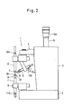
- Fig. 1 is a front view showing a spot welding machine according to one embodiment of the present invention;
- Fig. 2 is a side view of the spot welding machine shown in Fig. 1;
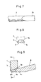
- Fig. 3 is a cutaway enlarged view of the distal end of a
first electrode 7 of the spot welding machine shown in Fig. 2; - Fig. 4 is a side view taken in the direction of arrow IV of Fig. 3;
- Fig. 5 is an end view taken in the direction of arrow V of Fig. 3;
- Fig. 6 is an enlarged view of the distal end of a
third electrode 9 of the spot welding machine shown in Fig. 2; - Fig. 7 is a bottom view of the
third electrode 9 shown in Fig. 6; - Fig. 8 is a sectional view taken along line VIII-VIII of Fig. 6;
- Fig. 9 is an enlarged sectional view showing a junction between the respective distal ends of the first and
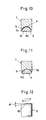
third electrodes - Fig. 10 is a sectional view taken along line X-X of Fig. 9;
- Fig. 11 is a sectional view showing the state of intimate contact between the electrodes shown in Fig. 10;
- Fig. 12 is an enlarged view of the distal end of a
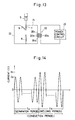
second electrode 8 of the spot welding machine shown in Fig. 1; - Fig. 13 is a circuit diagram of the spot welding machine shown in Fig. 1;
- Fig. 14 is a graph for illustrating a conduction method for the spot welding machine of the present invention, in terms of the time-based transition of the waveform of current supplied;
- Fig. 15 is an enlarged sectional side view of the principal part of the spot welding machine of Fig. 1, showing a state such that a workpiece is held by means of the first to third electrodes;
- Fig. 16 is an enlarged front view, partially in section, of the principal part of the spot welding machine of Fig. 1, showing the workpiece is held by means of the first to third electrodes;
- Fig. 17 is an enlarged front view of the principal part, showing the relationships between the electrodes and the workpiece at the time of welding the workpiece shown in Figs. 15 and 16;
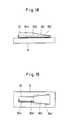
- Fig. 18 is a side view of a weld portion after the welding process shown in Fig. 17;
- Fig. 19 is a plan view of the weld portion after the welding process shown in Fig. 17;
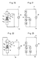
- Fig. 20 is a block diagram schematically showing a method of electrically connecting the electrodes and a welding transformer of the spot welding machine of the present invention;
- Fig. 21 is an equivalent circuit diagram showing a simpler version of the block diagram of Fig. 20;
- Fig. 22 is a schematic block diagram showing a comparable method of electrically connecting the electrodes and the welding transformer;
- Fig. 23 is an equivalent circuit diagram showing a simpler version of the block diagram of Fig. 22;
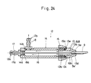
- Fig. 24 is a sectional view showing an example of an electrode holder for the spot welding machine according to the present invention;
- Fig. 25 is a sectional view showing a modification of the electrode holder for the spot welding machine shown in Fig. 24; and
- Fig. 26 is a sectional view of an electrode holder for a prior art spot welding machine.
- Referring first to the drawings of Figs. 1 and 2, an outline of a spot welding machine according to the present invention will be described.
- A
body frame 3 is fixedly mounted on abase 2 of aspot welding machine 1, and an upperelectrode supporting arm 4 is attached to the upper portion of the front face of thebody frame 3 for vertical movement. Theupper arm 4 supportselectrode holders arm 4 is driven vertically by means of anactuator 5, such as an air cylinder. Theactuator 5 is provided with an adjustingscrew 5a for regulating the vertical stroke of the upperelectrode supporting arm 4, i.e., those of theelectrode holders third electrodes electrodes screw 5a. - The
electrode holder 10 includes a lower portion, which supports the proximal end of thefirst electrode 7 with the distal end thereof downward, and an upper portion supported by the upperelectrode supporting arm 4. Theelectrode holder 10 has a water-cooled jacket structure, as mentioned later, such that thefirst electrode 7 is cooled by means of cooling water. Thethird electrode 9 includes aproximal end portion 9e (see Fig. 24) and adistal end portion 9a (see Fig. 6). Theproximal end portion 9e is supported by theelectrode holder 12 which is disposed behind thefirst electrode 7, as shown in Fig. 2. Thedistal end portion 9a, which extends diagonally downward from theproximal end portion 9e, abuts intimately against the distal end (workpiece engaging region) of thefirst electrode 7. Theelectrode holder 12 also has a water-cooled jacket structure, as mentioned later, such that theelectrode 9 is cooled by means of the cooling water. - A lower
electrode supporting arm 6 is fixedly mounted on that portion of the upper surface of thebase 2 which faces the upperelectrode supporting arm 4 from below. Anelectrode holder 11 supporting a second electrode (stationary electrode) 8 is supported by thelower arm 6. Thesecond electrode 8 is fixed with its distal end face upward so that it faces the end face of thefirst electrode 7 and a slant end face (mentioned later) of thethird electrode 9. Theelectrode holder 11 for thesecond electrode 8 is also composed of a water-cooled jacket so that theelectrode 8 is water-cooled. Theelectrode holders water supply ports water discharge ports - As shown in Figs. 3 to 5, the
first electrode 7 is formed of a solid round rod, and the end face of itsdistal end 7a is cut aslant at a predetermined angle 0 to a plane perpendicular to the axis of theelectrode 7. An engaginggroove 7b, having a substantially semicircular cross section with a radius r1, is cut in the center of the end face. As shown in Fig. 3, the engaginggroove 7b includes twogrooves grooves groove 7c is equal to the angle 0, while the gradient of the bottom surface of thegroove 7d is greater than the gradient 0 of the bottom surface of thegroove 7c. Thegroove 7c serves for the close engagement to thethird electrode 9, while thegroove 7d serves as an escape portion at which the first andthird electrodes second electrode 8 is formed of a solid round rod having the same diameter as thefirst electrode 7. - As shown in Figs. 6 to 8, the
third electrode 9 is formed of a solid round rod having a diameter a little smaller than that of thefirst electrode 7. Thedistal end 9a is cut aslant by a plane which contains the diameter of anend face 9d and is inclined at the angle 0 to the axis of theelectrode 9. Oneside face 9b of thedistal end 9a is a curved surface whose radius of curvature is r2 « r1), and the other side face 9c of the distal end is flat. Thecurved side face 9b is adapted to be engagedly fitted in thegroove 7c of the engaginggroove 7b of thefirst electrode 7, while the other side face 9c is adapted to engage a workpiece. - Thus, the
curved face 9b of thedistal end 9a of thethird electrode 9 is fitted in thegroove 7c of thefirst electrode 7, and the difference Ar (= r1 - r2) between the respective radii r1 and r2 of the inner curved surface of thegroove 7c and thecurved face 9b is adjusted to a value a little greater than the regular fit tolerance. For example, the radius r2 of thecurved face 9b of thethird electrode 9 is preferably set to a value within a range given by 0.93r1 < r2 < 0.95 r1, compared with the radius r1 of thegroove 7c of thefirst electrode 7. - The upper limit value of the radius r2 is set to a value such that it not only absorbs the machining and mounting errors of the first and
third electrodes distal end 9a of theelectrode 9 is fitted in thegroove 7c of theelectrode 7, as shown in Figs. 9 to 11, but also allows the curved inner surface of thegroove 7c and the curved side faces 9b of theelectrode 9 to be securely in contact with each other at their center P. The lower limit value of the radius r2 is adjusted to a minimum value such that the substantially whole regions of the two abutting curved surfaces can satisfactorily engage to each other by electrolytic corrosion, as shown in Fig. 11, when current flows through the abutting electrodes. Since the inner surface of thegroove 7c and theside face 9b are curved, they can enjoy a wider engagement area than when they are flat. - Thus, the
curved face 9b of thethird electrode 9 can be prevented from being located to one-side of thegroove 7c of thefirst electrode 7 in a manner such that only part of thecurved face 9b engages the inner surface of thegroove 7c. Moreover, since the radius r2 of thecurved face 9b is bound to be smaller than the radius r1 of thegroove 7c an awkward situation such as the central portion of theface 9b not being in contact with the inner surface of thegroove 7c although theface 9b engages either edge of thegroove 7c can be avoided. - Although the
groove 7c of thefirst electrode 7 and thedistal end 9a of thethird electrode 9 are connected electrically by engagement, thegroove 7d of theelectrode 7 is isolated from thedistal end 9a of theelectrode 9. Accordingly, a welding current, flowing from theelectrode 7 to theelectrode 9, passes predominantly through thegroove 7c and the region engaging thereto. Thus, heat can be concentrated in acontact region 9a' of thedistal end 9a of theelectrode 9. - The
first electrode 7 is located vertically with its distal end face downward, and thethird electrode 9 is held against theelectrode 7 so as to decline to thegroove 7c from behind and above the same. In this state, thedistal end 9a is fitted intimately in thegroove 7c, and theflat face 9c, which is expected to engage the workpiece, extends horizontally. Thus, thethird electrode 9 is positioned at the aforesaid predetermined angle 0 to a horizontal plane. The angle 0 is set within a range of 8 to 300, and preferably, is adjusted to 13 ° or thereabout. By tilting the contact portions of the first andthird electrodes - As shown in Fig. 12, moreover, the
second electrode 8 is formed so that itsend face 8a, which is opposed to thethird electrode 9, is slanted at a predetermined angle 0' to the other side face 9c of the distal end of theelectrode 9. Theend face 8a is slanted with respect to a loading direction A or an unloading direction B of the workpiece. Preferably, theslant end face 8a is adjusted so that its upper end is in alignment with the distal end side of the workpiece. Usually, the gradient 0' of theend face 8a of theelectrode 8 ranges from about 1 to 30. If the workpiece is a wire member, however, the gradient 0' should preferably be adjusted in dependence upon the diameter of the wire member. - The first and
third electrodes second electrode 8. For example, molybdenum, tungsten, etc. may be suitably used as the materials of the first andthird electrodes second electrode 8 include copper containing 35-% tungsten by weight, tungsten containing silver, tungsten containing zirconium, etc., for example. Besides these materials, tungsten alloys with the same electrical characteristics may be used for the first tothird electrodes 7 to 9. - As shown in Fig. 13, the proximal end side of the
first electrode 7 is connected to oneend 20c of asecondary coil 20a of awelding transformer 20 by means of aconductor wire 21. The proximal end side of thethird electrode 9, along with that of thesecond electrode 8, is connected to the other end 20d of thesecondary coil 20a by means of aconductor wire 22. Aprimary coil 20b of thewelding transformer 20 is connected to apower control circuit 23. - The
power control circuit 23 supplies theprimary coil 20b of thetransformer 20 with, e.g., commercial AC power of 50 Hz, and causes thesecondary coil 20a to be supplied with a welding AC current of 50 Hz for a predetermined period T. Thus, separation of a coating film from the workpiece by fusion and welding are effected continuously. Thepower control circuit 23 is constructed so that the workpiece conduction period T is divided into two periods; a first-half period (hereinafter referred to as separation period) Ta, required for the separation of the coating film by fusion, and a second-half period (hereinafter referred to as welding period) Tb, required for actual welding, as shown in Fig. 14, and that a current (hereinafter referred to as separation current) la, required for the separation of the coating film, and a current (hereinafter referred to as welding current) Ib, required for the actual welding, can be caused to flow through thesecondary coil 20a of thetransformer 20 during the separation period Ta and the welding period Tb, respectively. - A sequence of operations and the functions of the
spot welding machine 1, constructed in this manner, will now be described. In this case, the workpiece used includes, for example, aconductor wire 30, composed of acopper core 30a with a core diameter of 0.34q) coated withpolyesterimide 30b, and an electrically conductive terminal member 31 (see Fig. 15), which are to be welded together. - First, the cooling water is fed to the respective water-cooled jackets of the
electrode holders 10 to 12. Then, as shown in Figs. 1, 2, 15 and 16, theconductor wire 30 is put on a desired portion of the top surface of theterminal member 31, and the resulting workpiece is fed in the direction of arrow A (see Fig. 16) to be placed on thesecond electrode 8. Subsequently, theactuator 5 is worked to lower the first andthird electrodes flat face 9c of theelectrode 9 against the workpiece with a required force of pressure, so that the workpiece is held between thesecond electrode 8 and the combination of the first andthird electrodes - Then, the
power control circuit 23 is switched on to energize thesecondary coil 20a of thetransformer 20. Thecontrol circuit 23 causes the separation current la (see Fig. 14) to flow through thesecondary coil 20a during the separation period Ta, which starts at the beginning of the current supply. At the start of the supply of the separation current la, theconductor wire 30 is covered with thecoating film 30b, and therefore, is insulated. Accordingly, the current cannot flow directly between the first andsecond electrodes conductor wire 21, first andthird electrodes conductor wire 22, andsecondary coil 20a. Since theelectrodes electrode 8, and are connected only at their distal end portions abutting against each other, thecontact region 9a' (see Fig. 9), which has a relatively high resistance, is quickly heated to high temperature as the current is supplied. - As the first and
third electrodes coating film 30b on theconductor wire 30 is melted and separated. Thereupon, thecopper core 30a is exposed to allow theelectrode 7 and theterminal member 31 to conduct during the latter half of the separation period Ta. Thus, thecoating film 30b is separated satisfactorily from thecore 30a. As a result of such conduction, the welding current starts to flow between the first andsecond electrodes secondary coil 20a is supplied with the welding current Ib which is greater than the separation current la. - Part of the welding current Ib is by-passed through the course from the
first electrode 7 to thethird electrodes 9. Also, the current Ib is reduced as the resistance increases due to the heating, electrolytic corrosion, oxidation, etc. of the electrodes. In anticipation of such a reduction, however, the welding current Ib is set to the aforesaid relatively great value. Accordingly, thepower control circuit 23 can provide a welding current flow great enough for the welding of the workpiece during the weld period Tb. Thus, during the welding period Tb, thecopper core 30a and theterminal member 31 are welded together. - Since the
end face 8a of thesecond electrode 8 is slanted, in the meantime, theterminal member 31 and thecopper core 30a are inclined along theend face 8a by the force of pressure from the first andthird electrodes contact surface 30c of thecopper core 30a in contact with thethird electrode 9 is tapered from the proximal side toward the distal side, as shown in Figs. 17 to 19. Thus, ajoint portion 30d of thecopper core 30a, connecting with the proximal end of a weld portion, in particular, can be prevented from being lowered in strength. If theend face 8a of thesecond electrode 8 is not slanted, that portion of thecore 30a in contact with thethird electrode 9, i.e., the weld portion, is flattened, as indicated by a two-dot chain line 30c' in Figs. 18 and 19. As a result, thejoint portion 30d connecting with the proximal end of the weld portion is lowered in strength. - In the embodiment described above, the
end face 8a of thesecond electrode 8 is slanted at the angle 0' to a horizontal plane, and theface 9c of thethird electrode 9 is horizontal. In contrast with this, however, theend face 8a of thesecond electrode 8 may be formed horizontally. In this case, theface 9c of thethird electrode 9 is slanted with respect to the loading direction or the unloading direction of the workpiece. - As described above, the heating of the first and
third electrodes coating film 30b by fusion, and the welding of thecopper core 30a and theterminal member 31 can be finished in a very short time. The weld time varies depending on the dimensions of the workpiece to be welded, e.g., the core diameter of theconductor wire 30, the thickness of theterminal member 31, etc. If the weld time is too short, the strength of the welded joint is not satisfactory. If the weld time is too long, on the other hand, thecopper core 30a may possibly be broken from pressure or undesirably annealed and become brittle. Thus, the weld time should be suitably adjusted in consideration of these circumstances. - When using a wire member composed of the 0.34-q) copper core coated with polyesterimide for use as the workpiece, the separation period Ta and the welding period Tb are set to approximately 0.3 sec (about 15 cycles) each, and the separation current la and the welding current Ib are adjusted to about 600 A and 800 A, respectively. Thus, the welding current Ib is greater than the separation current la (Ib > la). It is to be understood that the periods Ta and Tb and the currents la and Ib are adjusted to their respective optimum values depending on the core diameter, coating film thickness, etc. of the wire member. Naturally, also in this case, the welding current Ib is greater than the separation current la.
- The separation period Ta and the welding period Tb may be made continuous with each other so that the separation current la and the welding current Ib are supplied continuously. Alternatively, a very short cooling period (downtime), as short as one cycle or thereabout, may be interposed between the periods Ta and Tb.
- In the spot welding machine according to the present invention, the
electrodes 7 to 9 and thewelding transformer 20 should be connected in the manner shown in Fig. 13. The reason for this will now be described in detail. Referring first to Figs. 20 and 21, an equivalent circuit obtained with use of the method of connection of the invention will be explained. Let it be supposed that the internal resistances of the first, second, andthird electrodes third electrodes second electrode 8 and the other side face of the distal end of thethird electrode 9, including the contact resistances between the workpiece and the electrodes, is Rw. The circuit diagram of Fig. 20 can be replaced by the equivalent circuit diagram of Fig. 21 as its simpler version. In Fig. 21, resistors Ra, Rt, Rw and Rb are connected in series in the order named. These resistors, theconductor wire 22, thewelding transformer 20, and theconductor wire 21 constitute a closed circuit. A resistor Rc of thethird electrode 9 is disposed on a line which diverges, at one end thereof, from anode 24 between the resistors Rt and Rw and is connected in parallel with the resistors Rw and Rb. - As compared with the method of connection according to the present invention, a method for comparison may be proposed such that the proximal side of the
third electrode 9 is connected to one end of the secondary coil of thewelding transformer 20 by means of aconductor wire 25, and that the proximal side of thefirst electrode 7, along with that of thesecond electrode 8, is connected to the other end of the secondary coil by means of aconductor wire 26, as shown in Fig. 22. A connection circuit according to this alternative method can be simply represented by an equivalent circuit shown in Fig. 23. In Fig. 23, the resistors Rc, Rw and Rb are connected in series in the order named. These resistors, theconductor wire 26, thewelding transformer 20, and theconductor wire 25 constitute a closed circuit. The resistors Rt and Ra are arranged successively on a line which diverges from anode 27 between the resistors Rc and Rw and is connected in parallel with the resistors Rw and Rb. - The resistances Ra, Rb and Rc of the
electrodes - In the case of the spot welding machine of the present invention, all the separation current flows through a closed circuit composed of the
welding transformer 20,conductor wire 21, resistors Ra and Rt,node 24, resistor Rc, andconductor wire 22, in the initial stage of the separation period Ta, that is, during the period when the coating film is not melted yet and there is no conduction between the third andsecond electrodes second electrodes third electrode 9 continues to be heated even in the welding process. If the separation of the coating film is not finished yet at the end of the separation period Ta, therefore, heat is supplied for the separation during the first half of the succeeding welding period. Thus, even though the conduction time and the current value required for the processes of separation and welding somewhat change, due to variation in thickness of the conductor wires, deterioration of the electrodes, etc., the film separation and the welding can be accomplished satisfactorily. As a result, the quality of weld is subject to less variation, and a desired weld strength can be obtained securely. - According to the method for comparison, on the other hand, when part of the coating film is separated to allow the welding current to start flowing, the current flowing through the resistor Rt is reduced, so that the amount of heat produced for film separation becomes too small for satisfactory separation. If the welding process is started after the separation is completed, welding with use of the connection method for comparison can be effected with less current, by a margin corresponding to the absence of a current flow through the resistor Rt, than by the use of the connection method according to the present invention. Since the welding current flows before the coating film is not fully separated yet, however, the separation is not complete, so that the welding cannot be performed satisfactorily. Thus, the product quality, such as the weld strength for each workpiece, fluctuates due to variations of external factors, thereby lowering the yield.
- In the spot welding machine constructed in this manner, if the
third electrode 9 is heated unduly, the regular welding current may sometimes fail to flow during the welding process after the removal of the plastic coating film. Therefore, thethird electrode 9 should be specially cooled. This is done, for example, by a prior art water-cooling method, as shown in Fig. 26. In Fig. 26, a prior art water-cooledelectrode holder 49 includes aplug 50, a water-cooledjacket 52, and a fixingnut 53. Theelectrode 51 is supported by theplug 50 in a manner such that itsproximal end 51 a is fitted in ahole 50a bored in the distal end of theplug 50. Aproximal end 50b of theplug 50 is screwed in the distal end of the water-cooledjacket 52 in a liquid-tight manner, and is fixed by means of the fixingnut 53. The cooling water is circulated through thejacket 52, as indicated by the arrow of Fig. 26, whereby anproximal end face 50c of theplug 50 is cooled so that theelectrode 51 is cooled. - In the prior art water-cooled
electrode holder 49 described above, however, theplug 50 is first cooled by means of the cooling water, and theelectrode 51 is then cooled. In other words, theelectrode 51 is cooled indirectly, that is, through the medium of theplug 50, so that the cooling efficiency for theelectrode 51 is low. Thus, theelectrode 51 may possibly be overheated if the intervals between welding cycles are too short. It is necessary, therefore, to perform welding at intervals of 5 to 7 seconds or thereabout. This would result in lowering of the working efficiency of the spot welding machine. - The heating condition of the
electrode 51 may, for example, be monitored by means of a thermocouple embedded in theplug 50, or by detecting infrared rays. Since theelectrode 51 is fixed integrally to theplug 50, however, theplug 50 must be also replaced when theelectrode 51 is to be replaced with a new one. Thus, the use of the thermocouple is not economical. In any case, a special device is required for monitoring the heating condition, so that the machine is expensive. - Fig. 24 shows the
electrode holder 12 used in the spot welding machine according to the present invention. Theelectrode holder 12 is composed, for example, of aplug 13 for supporting thethird electrode 9, a water-cooledjacket 14 for supporting theplug 13, a fixingnut 15 for fixing theplug 13 to thejacket 14, and apipe 16 constituting a cooling water passage. Theplug 13 has adistal end 13a shaped like a truncated cone and a cylindricalproximal end 13b. A stepped portion 13e is formed between theends proximal end 13b is threaded. Amajor hole 13c and aminor hole 13d are bored coaxially through theplug 13, the former being larger in diameter than the latter. Themajor hole 13c opens to the central portion of the end face of theproximal end 13b, while theminor hole 13d opens to the central portion of the distal end face of theplug 13. Theplug 13, shaped like this, is formed integrally from an electrically conductive material. - A
rear end 9e of thethird electrode 9 is fitted in theminor hole 13d, which opens to the distal end face of theplug 13, in a manner such that itsextreme end portion 9e' projects into themajor hole 13c for a predetermined length. Theelectrode 9 is immovably fixed to theplug 13 to be connected electrically thereto, by soldering. - The water-cooled
jacket 14 has the shape of a bottomed hollow cylinder. The outer and inner peripheral surfaces of the open end portion of thejacket 14 are both threaded. Tappedholes 14a and 14b are bored through the closed end face of thejacket 14 and a specific portion of the side wall in the vicinity thereof, respectively. Theproximal end 13b of theplug 13 is screwed in the open end of thejacket 14 in a liquid-tight manner. The fixingnut 15 is interposed between theplug 13 and thejacket 14. More specifically, thenut 15 is screwed on the open end of thejacket 14 so that itsdistal end 15a is sandwiched between the open end face of thejacket 14 and the stepped portion 13e of theplug 13. - After the
proximal end 13b of theplug 13 is screwed into the water-cooledjacket 14, thedistal end 15a of the fixingnut 15 is pressed against the stepped portion 13e of theplug 13, thereby forcing theplug 13 outward from the open end of thejacket 14. By doing this, thejacket 14 and theplug 13 are fixed firmly to each other. When theplug 13 is fixedly screwed in thejacket 14, thethird electrode 9 is located in alignment with the axis of thejacket 14, and theend face 9e' of theproximal end 9e is situated inside thejacket 14. -
Connectors holes 14a and 14b of the water-cooledjacket 14, respectively. The cooling water is introduced into and discharged from thejacket 14 through theconnectors connectors water supply port 12a and a cooling-water discharge port 12b, respectively. Oneend 16a of theslender pipe 16 is fitted in ahole 17a, which extends along the axis of the oneconnector 17. On the other end side, thepipe 16 loosely penetrates thejacket 14 so as to extend substantially along the axis of thejacket 14 into themajor hole 13c. Theother end 16b faces theend face 9e' of thethird electrode 9 at a distance of several millimeters, preferably 1 to 3 mm or thereabout. Thepipe 16 serves as a passage through which the cooling water flows into a cooling-water space 14A on which theend face 9e' of thethird electrode 9 faces. Theconnectors pipe 16 is set in accordance with the pressure of the cooling water used. - The low-temperature cooling water delivered from the cooling system flows into the
pipe 16 through theconnector 17 of the water-cooledjacket 14, and is then sprayed through the open end of thepipe 16 onto theend face 9e' of theelectrode 9, thereby cooling theelectrode 9. Thus, theelectrode 9 is cooled directly by the cooling water, so that the cooling efficiency is improved. After cooling theelectrode 9, the cooling water flows in the direction indicated by the arrows, inside themajor hole 13c, thereby entering the inside space of the water-cooledjacket 14. Meanwhile, theplug 13 is cooled by the cooling water flowing in themajor hole 13c. Since thehole 13c is bored along the axis of theplug 13, the whole plug can be cooled with high efficiency. - The proximal end of the
electrode 9 is fitted in theminor hole 13d of theplug 13, so that theelectrode 9 is cooled also by theplug 13. In consequence, theelectrode 9 can be cooled more efficiently. After cooling theplug 13, the cooling water inside the water-cooledjacket 14 flows out therefrom through theconnector 18, and returns to the cooling system. Thus, theelectrode 9 can be cooled very satisfactorily, and can therefore be restrained from overheating. In this connection, the weld time interval of the spot welding machine of the present invention can be reduced to about 1 to 3 seconds, which is much shorter than in the case of the prior art machine. Thus, the working efficiency of the welding machine is improved. - The
second electrode 8, which is less susceptible to heat than the first andthird electrodes electrode holder 49 based on the conventional cooling system, as shown in Fig. 26, instead of using theelectrode holder 12 shown in Fig. 24. - An electrode holder 12' for a spot welding machine shown in Fig. 25 is a modification of the
electrode holder 12 of Fig. 24. As shown in Fig. 25, distal and proximal ends 13'a and 13'b of a plug 13' have the same outside diameter, and a land 13'f is formed at the junction of the two ends. The proximal end 13'b is simply fitted in the open end of the water-cooledjacket 14 without any threads on the end 13'b or the open end of thejacket 14. A distal end 15'a of a fixing nut 15' is made longer enough to be fitted on the distal end 13'a of the plug 13'. An O-ring 19 is interposed between the land 13'f of the plug 13' and the open end of thejacket 14. If the fixing nut 15' is tightened, in this arrangement, the land 13'f of the plug 13' is pressed liquid-tight against the open end of thejacket 14 by means of the distal end 15'a of the nut 15'. Thus, the water-cooledjacket 14 and the plug 13' can be easily coupled in liquid-tight relation, the plug 13' can be attached or detached with ease for the replacement of theelectrode 9.
Claims (11)
characterised in that the third electrode is interposed between said first electrode and said workpiece, and has a first distal-end side face (9b) abutting closely against said workpiece engaging end of said first electrode, and a second distal end side face (9c) in contact with said workpiece during use and in that the second closed circuit has a route passing through said first terminal, said first electrode, said third electrode, said workpiece, said second electrode, and said second terminal.

Priority Applications (2)
| Application Number | Priority Date | Filing Date | Title |
|---|---|---|---|
| EP93106593A EP0553903B1 (en) | 1987-03-23 | 1988-03-23 | Electrodes for a spot welding machine |
| AT88302577T ATE97600T1 (en) | 1987-03-23 | 1988-03-23 | SPOT WELDING MACHINE. |
Applications Claiming Priority (2)
| Application Number | Priority Date | Filing Date | Title |
|---|---|---|---|
| JP62065802A JPS63235081A (en) | 1987-03-23 | 1987-03-23 | Spot welding machine |
| JP65802/87 | 1987-03-23 |
Related Child Applications (1)
| Application Number | Title | Priority Date | Filing Date |
|---|---|---|---|
| EP93106593.2 Division-Into | 1993-04-23 |
Publications (4)
| Publication Number | Publication Date |
|---|---|
| EP0284376A2 EP0284376A2 (en) | 1988-09-28 |
| EP0284376A3 EP0284376A3 (en) | 1989-07-19 |
| EP0284376B1 true EP0284376B1 (en) | 1993-11-24 |
| EP0284376B2 EP0284376B2 (en) | 1997-07-16 |
Family
ID=13297522
Family Applications (2)
| Application Number | Title | Priority Date | Filing Date |
|---|---|---|---|
| EP93106593A Expired - Lifetime EP0553903B1 (en) | 1987-03-23 | 1988-03-23 | Electrodes for a spot welding machine |
| EP88302577A Expired - Lifetime EP0284376B2 (en) | 1987-03-23 | 1988-03-23 | Spot welding machine |
Family Applications Before (1)
| Application Number | Title | Priority Date | Filing Date |
|---|---|---|---|
| EP93106593A Expired - Lifetime EP0553903B1 (en) | 1987-03-23 | 1988-03-23 | Electrodes for a spot welding machine |
Country Status (6)
| Country | Link |
|---|---|
| US (1) | US4835356A (en) |
| EP (2) | EP0553903B1 (en) |
| JP (1) | JPS63235081A (en) |
| KR (1) | KR960005712B1 (en) |
| AT (2) | ATE154272T1 (en) |
| DE (2) | DE3885778T3 (en) |
Families Citing this family (13)
| Publication number | Priority date | Publication date | Assignee | Title |
|---|---|---|---|---|
| EP0456967B1 (en) * | 1990-05-16 | 1996-09-11 | Akio Hirane | Spot welder and method for using |
| US5286945A (en) * | 1990-05-30 | 1994-02-15 | Kabushiki Kaisha Yosetsu Gijutsu Kenkyusho | Apparatus for heating workpieces to bond the same |
| JPH06253431A (en) * | 1992-12-28 | 1994-09-09 | Seiwa Seisakusho:Kk | Method for removing insulating coating of conductive wire therefor |
| US6621037B2 (en) | 1997-10-16 | 2003-09-16 | Magna International Inc. | Welding material with conductive sheet and method |
| US6713707B2 (en) | 1997-10-16 | 2004-03-30 | Magna International, Inc. | Welding material and method without carrier |
| US6689982B2 (en) | 1997-10-16 | 2004-02-10 | Magna International, Inc. | Apparatus and method for welding aluminum tubes |
| US6566624B2 (en) * | 2000-03-03 | 2003-05-20 | Magna International Inc. | Welding assembly with nestable conductive ends |
| US6528750B1 (en) * | 2000-12-08 | 2003-03-04 | Joyal Products, Inc. | Heat/pressure fusing wire to terminal apparatus and method |
| US9321122B2 (en) * | 2005-12-06 | 2016-04-26 | Magna International Inc. | Spot welding tip for a spot welding machine |
| CN100409991C (en) * | 2006-05-19 | 2008-08-13 | 广州金升阳科技有限公司 | Spot welding method for welding wire and lead frame |
| US9969026B2 (en) | 2011-08-25 | 2018-05-15 | GM Global Technology Operations LLC | Weld schedule for resistance spot welding of aluminum alloy workpieces |
| US10252369B2 (en) * | 2015-07-07 | 2019-04-09 | GM Global Technology Operations LLC | Cooling to control thermal stress and solidification for welding of dissimilar materials |
| CN111618409A (en) * | 2020-06-30 | 2020-09-04 | 马鞍山久想电气有限公司 | Welding device for connecting terminal of high-voltage coil of epoxy resin dry-type transformer |
Family Cites Families (8)
| Publication number | Priority date | Publication date | Assignee | Title |
|---|---|---|---|---|
| US2479547A (en) * | 1946-10-02 | 1949-08-16 | Budd Co | Adjustable tip for resistance welding electrodes |
| FR1529353A (en) * | 1967-06-28 | 1968-06-14 | Wells Electronics | Method and apparatus for soldering insulated electrical conductors |
| US3626139A (en) * | 1969-02-20 | 1971-12-07 | Oran J Sands | Welding apparatus |
| DE2214749A1 (en) * | 1972-03-25 | 1973-09-27 | Messer Griesheim Gmbh | METHOD AND DEVICE FOR CONNECTING THIN METAL WIRES TO A METALLIC WORKPIECE |
| JPS5729996U (en) * | 1980-07-23 | 1982-02-17 | ||
| JPS59104279A (en) * | 1982-12-06 | 1984-06-16 | Kobe Steel Ltd | Resistance welding method of composite metallic material having resin film |
| JPS60240389A (en) * | 1984-05-15 | 1985-11-29 | Yashima Denki Kk | Spot welding method |
| JPH0798995B2 (en) * | 1992-02-03 | 1995-10-25 | 象印チエンブロック株式会社 | Link chain continuous surface treatment equipment |
-
1987
- 1987-03-23 JP JP62065802A patent/JPS63235081A/en active Granted
-
1988
- 1988-03-16 US US07/168,933 patent/US4835356A/en not_active Expired - Lifetime
- 1988-03-22 KR KR1019880003070A patent/KR960005712B1/en not_active Expired - Fee Related
- 1988-03-23 DE DE3885778T patent/DE3885778T3/en not_active Expired - Fee Related
- 1988-03-23 AT AT93106593T patent/ATE154272T1/en not_active IP Right Cessation
- 1988-03-23 EP EP93106593A patent/EP0553903B1/en not_active Expired - Lifetime
- 1988-03-23 EP EP88302577A patent/EP0284376B2/en not_active Expired - Lifetime
- 1988-03-23 AT AT88302577T patent/ATE97600T1/en not_active IP Right Cessation
- 1988-03-23 DE DE3855941T patent/DE3855941T2/en not_active Expired - Fee Related
Also Published As
| Publication number | Publication date |
|---|---|
| ATE154272T1 (en) | 1997-06-15 |
| DE3855941D1 (en) | 1997-07-17 |
| EP0284376A3 (en) | 1989-07-19 |
| DE3855941T2 (en) | 1997-12-04 |
| EP0284376A2 (en) | 1988-09-28 |
| ATE97600T1 (en) | 1993-12-15 |
| EP0284376B2 (en) | 1997-07-16 |
| DE3885778D1 (en) | 1994-01-05 |
| US4835356A (en) | 1989-05-30 |
| EP0553903A2 (en) | 1993-08-04 |
| EP0553903A3 (en) | 1993-08-25 |
| KR880010859A (en) | 1988-10-25 |
| KR960005712B1 (en) | 1996-05-01 |
| DE3885778T2 (en) | 1994-03-17 |
| EP0553903B1 (en) | 1997-06-11 |
| JPS63235081A (en) | 1988-09-30 |
| JPH0549393B2 (en) | 1993-07-26 |
| DE3885778T3 (en) | 1997-10-16 |
Similar Documents
| Publication | Publication Date | Title |
|---|---|---|
| EP0553903B1 (en) | Electrodes for a spot welding machine | |
| US5200594A (en) | Electrode for use in plasma arc working torch | |
| US5229568A (en) | Spot resistance welding method and welding electrode for implementing the method | |
| US3943323A (en) | Bonding apparatus | |
| GB2081156A (en) | Stranded Electrode for Use in Welding | |
| US4404456A (en) | Micro-arc welding/brazing of metal to metal and metal to ceramic joints | |
| US5140126A (en) | Resistance welding method and resistance welding device for lead acid battery | |
| US4947019A (en) | Composite electrode for resistance welding | |
| JPH0322260B2 (en) | ||
| GB2356593A (en) | Method of manufacturing spark plug with noble metal chip for internal combustion engine | |
| US7355142B2 (en) | Resistance welding electrode, welded copper flex lead, and method for making same | |
| JPH09323173A (en) | Welding power supply device and control method thereof | |
| US4438322A (en) | Ceramic coated electric heater assembly for tools | |
| JPH04137516A (en) | Method and device for connecting magnet wire with lead wire | |
| JPH0866764A (en) | Soldering equipment | |
| RU2072286C1 (en) | Method of connecting wires made of materials with different physical and chemical properties | |
| US4296303A (en) | Method for making intercell connections in multi-cell storage battery | |
| JPH07106462B2 (en) | Energizing the spot welder | |
| JP2008073728A (en) | Method for joining metal members | |
| JPH0573516B2 (en) | ||
| US4701933A (en) | Method of supplying heat energy to a metal melt or the like and a heating element for use with said method | |
| US1990314A (en) | Welding refractory metal | |
| JPH0549394B2 (en) | ||
| JPS6126519A (en) | Junction electrode for glass smelting | |
| JPH0399784A (en) | Spot welding equipment |
Legal Events
| Date | Code | Title | Description |
|---|---|---|---|
| PUAI | Public reference made under article 153(3) epc to a published international application that has entered the european phase |
Free format text: ORIGINAL CODE: 0009012 |
|
| AK | Designated contracting states |
Kind code of ref document: A2 Designated state(s): AT BE CH DE ES FR GB IT LI NL SE |
|
| RAP1 | Party data changed (applicant data changed or rights of an application transferred) |
Owner name: KYOSHIN KOGYO CO., LTD |
|
| PUAL | Search report despatched |
Free format text: ORIGINAL CODE: 0009013 |
|
| AK | Designated contracting states |
Kind code of ref document: A3 Designated state(s): AT BE CH DE ES FR GB IT LI NL SE |
|
| RHK1 | Main classification (correction) |
Ipc: B23K 11/32 |
|
| 17P | Request for examination filed |
Effective date: 19900110 |
|
| 17Q | First examination report despatched |
Effective date: 19910506 |
|
| GRAA | (expected) grant |
Free format text: ORIGINAL CODE: 0009210 |
|
| AK | Designated contracting states |
Kind code of ref document: B1 Designated state(s): AT BE CH DE ES FR GB IT LI NL SE |
|
| PG25 | Lapsed in a contracting state [announced via postgrant information from national office to epo] |
Ref country code: IT Free format text: LAPSE BECAUSE OF FAILURE TO SUBMIT A TRANSLATION OF THE DESCRIPTION OR TO PAY THE FEE WITHIN THE PRE;WARNING: LAPSES OF ITALIAN PATENTS WITH EFFECTIVE DATE BEFORE 2007 MAY HAVE OCCURRED AT ANY TIME BEFORE 2007. THE CORRECT EFFECTIVE DATE MAY BE DIFFERENT FROM THE ONE RECORDED.SCRIBED TIME-LIMIT Effective date: 19931124 Ref country code: FR Effective date: 19931124 Ref country code: AT Effective date: 19931124 Ref country code: SE Effective date: 19931124 Ref country code: ES Free format text: THE PATENT HAS BEEN ANNULLED BY A DECISION OF A NATIONAL AUTHORITY Effective date: 19931124 Ref country code: LI Effective date: 19931124 Ref country code: BE Effective date: 19931124 Ref country code: CH Effective date: 19931124 Ref country code: NL Effective date: 19931124 |
|
| REF | Corresponds to: |
Ref document number: 97600 Country of ref document: AT Date of ref document: 19931215 Kind code of ref document: T |
|
| XX | Miscellaneous (additional remarks) |
Free format text: TEILANMELDUNG 93106593.2 EINGEREICHT AM 23/03/88. |
|
| REF | Corresponds to: |
Ref document number: 3885778 Country of ref document: DE Date of ref document: 19940105 |
|
| REG | Reference to a national code |
Ref country code: CH Ref legal event code: PL |
|
| EN | Fr: translation not filed | ||
| NLV1 | Nl: lapsed or annulled due to failure to fulfill the requirements of art. 29p and 29m of the patents act | ||
| PLBI | Opposition filed |
Free format text: ORIGINAL CODE: 0009260 |
|
| 26 | Opposition filed |
Opponent name: MESSER GRIESHEIM SCHWEISSTECHNIK GMBH & CO. Effective date: 19940824 |
|
| PLAW | Interlocutory decision in opposition |
Free format text: ORIGINAL CODE: EPIDOS IDOP |
|
| PLAW | Interlocutory decision in opposition |
Free format text: ORIGINAL CODE: EPIDOS IDOP |
|
| PUAH | Patent maintained in amended form |
Free format text: ORIGINAL CODE: 0009272 |
|
| STAA | Information on the status of an ep patent application or granted ep patent |
Free format text: STATUS: PATENT MAINTAINED AS AMENDED |
|
| 27A | Patent maintained in amended form |
Effective date: 19970716 |
|
| AK | Designated contracting states |
Kind code of ref document: B2 Designated state(s): AT BE CH DE ES FR GB IT LI NL SE |
|
| REG | Reference to a national code |
Ref country code: CH Ref legal event code: AEN Free format text: AUFRECHTERHALTUNG DES PATENTES IN GEAENDERTER FORM |
|
| EN | Fr: translation not filed | ||
| PGFP | Annual fee paid to national office [announced via postgrant information from national office to epo] |
Ref country code: GB Payment date: 19980319 Year of fee payment: 11 |
|
| PGFP | Annual fee paid to national office [announced via postgrant information from national office to epo] |
Ref country code: DE Payment date: 19980331 Year of fee payment: 11 |
|
| PG25 | Lapsed in a contracting state [announced via postgrant information from national office to epo] |
Ref country code: GB Free format text: LAPSE BECAUSE OF NON-PAYMENT OF DUE FEES Effective date: 19990323 |
|
| GBPC | Gb: european patent ceased through non-payment of renewal fee |
Effective date: 19990323 |
|
| PG25 | Lapsed in a contracting state [announced via postgrant information from national office to epo] |
Ref country code: DE Free format text: LAPSE BECAUSE OF NON-PAYMENT OF DUE FEES Effective date: 20000101 |