EP0284167B1 - Drive control system for hydraulic machine - Google Patents
Drive control system for hydraulic machine Download PDFInfo
- Publication number
- EP0284167B1 EP0284167B1 EP88200562A EP88200562A EP0284167B1 EP 0284167 B1 EP0284167 B1 EP 0284167B1 EP 88200562 A EP88200562 A EP 88200562A EP 88200562 A EP88200562 A EP 88200562A EP 0284167 B1 EP0284167 B1 EP 0284167B1
- Authority
- EP
- European Patent Office
- Prior art keywords
- hydraulic
- signal
- control
- cut
- manipulation
- Prior art date
- Legal status (The legal status is an assumption and is not a legal conclusion. Google has not performed a legal analysis and makes no representation as to the accuracy of the status listed.)
- Expired - Lifetime
Links
Images



Classifications
-
- F—MECHANICAL ENGINEERING; LIGHTING; HEATING; WEAPONS; BLASTING
- F15—FLUID-PRESSURE ACTUATORS; HYDRAULICS OR PNEUMATICS IN GENERAL
- F15B—SYSTEMS ACTING BY MEANS OF FLUIDS IN GENERAL; FLUID-PRESSURE ACTUATORS, e.g. SERVOMOTORS; DETAILS OF FLUID-PRESSURE SYSTEMS, NOT OTHERWISE PROVIDED FOR
- F15B9/00—Servomotors with follow-up action, e.g. obtained by feed-back control, i.e. in which the position of the actuated member conforms with that of the controlling member
- F15B9/02—Servomotors with follow-up action, e.g. obtained by feed-back control, i.e. in which the position of the actuated member conforms with that of the controlling member with servomotors of the reciprocatable or oscillatable type
- F15B9/08—Servomotors with follow-up action, e.g. obtained by feed-back control, i.e. in which the position of the actuated member conforms with that of the controlling member with servomotors of the reciprocatable or oscillatable type controlled by valves affecting the fluid feed or the fluid outlet of the servomotor
- F15B9/09—Servomotors with follow-up action, e.g. obtained by feed-back control, i.e. in which the position of the actuated member conforms with that of the controlling member with servomotors of the reciprocatable or oscillatable type controlled by valves affecting the fluid feed or the fluid outlet of the servomotor with electrical control means
-
- G—PHYSICS
- G05—CONTROLLING; REGULATING
- G05B—CONTROL OR REGULATING SYSTEMS IN GENERAL; FUNCTIONAL ELEMENTS OF SUCH SYSTEMS; MONITORING OR TESTING ARRANGEMENTS FOR SUCH SYSTEMS OR ELEMENTS
- G05B19/00—Program-control systems
- G05B19/02—Program-control systems electric
- G05B19/18—Numerical control [NC], i.e. automatically operating machines, in particular machine tools, e.g. in a manufacturing environment, so as to execute positioning, movement or co-ordinated operations by means of program data in numerical form
- G05B19/19—Numerical control [NC], i.e. automatically operating machines, in particular machine tools, e.g. in a manufacturing environment, so as to execute positioning, movement or co-ordinated operations by means of program data in numerical form characterised by positioning or contouring control systems, e.g. to control position from one programmed point to another or to control movement along a programmed continuous path
- G05B19/40—Open loop systems, e.g. using stepping motor
-
- G—PHYSICS
- G05—CONTROLLING; REGULATING
- G05B—CONTROL OR REGULATING SYSTEMS IN GENERAL; FUNCTIONAL ELEMENTS OF SUCH SYSTEMS; MONITORING OR TESTING ARRANGEMENTS FOR SUCH SYSTEMS OR ELEMENTS
- G05B2219/00—Program-control systems
- G05B2219/30—Nc systems
- G05B2219/35—Nc in input of data, input till input file format
- G05B2219/35438—Joystick
-
- G—PHYSICS
- G05—CONTROLLING; REGULATING
- G05B—CONTROL OR REGULATING SYSTEMS IN GENERAL; FUNCTIONAL ELEMENTS OF SUCH SYSTEMS; MONITORING OR TESTING ARRANGEMENTS FOR SUCH SYSTEMS OR ELEMENTS
- G05B2219/00—Program-control systems
- G05B2219/30—Nc systems
- G05B2219/36—Nc in input of data, input key till input tape
- G05B2219/36551—Inhibiting control after detecting data error
-
- G—PHYSICS
- G05—CONTROLLING; REGULATING
- G05B—CONTROL OR REGULATING SYSTEMS IN GENERAL; FUNCTIONAL ELEMENTS OF SUCH SYSTEMS; MONITORING OR TESTING ARRANGEMENTS FOR SUCH SYSTEMS OR ELEMENTS
- G05B2219/00—Program-control systems
- G05B2219/30—Nc systems
- G05B2219/41—Servomotor, servo controller till figures
- G05B2219/41309—Hydraulic or pneumatic drive
Definitions
- This invention relates to a drive control system for a hydraulic machine, specifically, to a drive control system equipped with an electric lever device for controlling the hydraulic actuator of a machine such as a hydraulic shovel.
- a machine such as a hydraulic shovel is generally equipped with plural hydraulic actuators. These hydraulic actuators are individually controlled by corresponding actuation control devices which include a manipulation lever device. Specific examples of the actuation control device may include those making use of an electric lever device.
- Such an electric lever device has a manipulation lever and an output device for generating an electrical manipulation signal corresponding to the degree of manipulation of the lever (for example, a potentiometer), a control valve connected to a hydraulic circuit for actuating a hydraulic actuator, a controller unit having a main controller for receiving the manipulation signal from the electric lever device and computing a control signal for the control valve on the basis of the manipulation signal, and an output device for generating an electrical actuation signal corresponding to the control signal.
- a main power supply is also provided to drive the controller unit.
- the controller unit includes a power supply for the main controller and another power supply for the output device. The power supplies are both connected to the main power supply.
- the corresponding number of control valves, electric lever devices, and output devices of the controller unit are
- the controller unit is brought into a driven state upon connection of the main controller's power supply and the power supply for the output devices to the main power supply.
- an electrical signal corresponding to the degree of manipulation of the lever is outputted from the potentiometer to the controller unit so that an electrical actuation signal corresponding to the manipulation signal is produced by the main controller and output device of the controller unit.
- the control valve is a solenoid-operated valve
- the solenoid-operated valve is actuated directly by the actuation signal.
- control valve is a hydraulic pilot-operated valve
- the electrical actuation signal is converted to a hydraulic signal by an electrical signal/hydraulic signal converter to actuate the hydraulic pilot-operated valve.
- the hydraulic actuator is actuated to drive the working member with which the hydraulic actuator is associated.
- the hydraulic machine is a construction machine (for example, a hydraulic shovel for digging or excavating the earth)
- the above-mentioned hydraulic actuators are a boom cylinder, an arm cylinder, a bucket cylinder, a swivel motor, etc.
- the aforementioned working members include a boom driven by the boom cylinder, an arm driven by the arm cylinder, a bucket driven by the bucket cylinder, a swivel cabin driven by the swivel motor, etc.
- DE A-2631530 discloses a drive control system equipped with an electric lever device in which the electric lever device is provided with a switch for sensing the neutral position of a manipulation lever. While the manipulation lever is at the neutral position, the switch is kept open so as to inhibit the actuation of a manipulation signal output device.
- a problem or noise jamming, has occurred in the electric lever device and a false signal is about to be outputted as a result.
- the above construction opens the switch when the manipulation lever is shifted back to the neutral position.
- the actuation of the output device is hence inhibited to avoid the output of the false signal.
- the safety of the work is hence ensured.
- the prevention of a false signal occurring due to trouble, or jamming caused by noise or similar trouble is limited to the electric lever device.
- the conventional system cannot inhibit the output of a false signal when the false signal is produced due to occurrence of trouble, jamming caused by noise or similar trouble in a signal conductor downstream of the electric lever device or in the controller unit. Even when the manipulation lever is at the neutral position, the control valve is actuated to drive the associated hydraulic actuator and working member, resulting in the problem that safety cannot be assured.
- An object of this invention is therefore to provide a drive control system for a hydraulic machine, which even when a trouble, jamming caused by noise or similar trouble occurs at least in a main controller of a controller unit, an electric lever device, a signal conductor between the main controller of the controller unit and the electric lever device or control equipment, does not produce any false signal so long as the manipulation lever is at the neutral position, and safety of work is hence ensured.
- the present invention provides a drive control system for a hydraulic machine.
- the drive control system includes an electric lever device equipped with a manipulation lever and a first output means for generating an electrical manipulation signal corresponding to the degree of manipulation of the lever, a control valve connected to a hydraulic circuit adapted to actuate a hydraulic actuator, and a control means equipped with a main controller for receiving the manipulation signal and computing a control signal on the basis of the manipulation signal, and a second output means for receiving the control signal and generating an electrical actuation signal for the control valve corresponding to the control signal, the system additionally comprising a neutral position sensing means provided with the electric lever device and adapted to sense a neutral position of the manipulation lever, and an inhibition means which receives an output signal from the neutral position sensing means, and, when the manipulation lever is at the neutral position, inhibits the transmission of a signal between the main controller of the control means and the control valve.
- the above inhibition means may be of such a type that the transmission of an electrical signal between the main controller of the control means and the control valve is inhibited.
- the drive control system is equipped with an electric signal/hydraulic signal converter means for converting an electrical actuation signal from the output means of the control means to a hydraulic drive signal (hereinafter abbreviated as "E/H converter") and the control valve is a hydraulic pilot-operated control valve
- the inhibition means may be of such a type that the transmission of a hydraulic signal between the E/H converter and the hydraulic pilot-operated control valve is inhibited.
- the drive control system may be provided additionally with a main power supply to actuate the control means; and the inhibition means may cut off an electrical connection between the main power supply and the control means.
- the inhibition means may cut off an electrical connection between the power supply for the output means and the output means.
- the inhibition means may also cut off an electrical connection between the output means of the control means and the control valve, an electrical connection between the main controller of the control means and the output means, and/or an electrical connection between the output means of the control means and an earth or ground.
- the inhibition means inhibits the transmission of a hydraulic signal between the E/H converter and the hydraulic pilot-operated control valve
- the inhibition means may cut off the transmission of a hydraulic connection between a hydraulic pressure source for the E/H converter and the E/H converter, or a hydraulic connection between the E/H converter and the control valve.
- a drive control system which is suitable for use in a hydraulic machine and is provided with a plurality of hydraulic actuators and hydraulic circuits of the same types as those described above and, further, with plural control valves, electric lever devices and output means of the control means, said valves, devices and output means being of the same types as the above-described valve, device and output means, in association with the respective hydraulic actuators and hydraulic circuits, the above-described neutral position sensing means is provided with each of the plural electric lever devices.
- the inhibition means may be constructed of a means which receives signals outputted from the individual neutral position sensing means and outputs an actuation signal when these signals all indicate that the corresponding manipulation levers are at their neutral positions respectively, and a single cut-off means for receiving the actuation signal and collectively inhibiting the transmission of signals between the main controller of the control means and the plural control valves.
- the inhibition means may also be constructed of a plurality of cut-off devices adapted to receive signals outputted respectively from the corresponding plural neutral position sensing means.
- each cut-off means inhibits the transmission of a signal between the main controller of the control means and its corresponding control valve, while the signal outputted from the corresponding neutral position sensing means indicates that the corresponding manipulation lever is at the neutral position.
- the inhibition means corresponding to the manipulation lever which has returned to the neutral position is actuated to cause the corresponding control valve to return without fail to the neutral valve position whether the other manipulation levers are at their neutral positions or not. It is hence possible to prevent the actuation of each control valve by a false signal independently of the manipulation levers of the other control valves. This assures the safety of each hydraulic actuator independently.
- plural cut-off means may cut off electrical connections between the power supply for the plural output means and the corresponding plural output means, electrical connections between the main controller and the corresponding plural output means, electrical connections between the corresponding plural output means and the corresponding plural control valves, or electrical connections between the corresponding plural output means and the earth.
- the plural cut-off means may also cut off hydraulic connections between the hydraulic pressure source and the corresponding plural E/H converters or hydraulic connections between the corresponding plural E/H converters and the corresponding plural hydraulic pilot-operated control valves.
- the above inhibition means may preferably be provided with a delay means for receiving a neutral signal from the neutral position sensing means before the neutral signal is inputted to the cut-off means.
- the provision of the delay means enables the input of the neutral signal to the cut-off means with a delay of a predetermined time period. It is hence possible to subject the neutral signal to functional processing at the main controller right after the manipulation lever has been shifted back to the neutral position, thereby avoiding the occurrence of shock on the corresponding working member.
- Each electric lever device may preferably be constructed of a movable pusher means responsive to each manipulation of the corresponding manipulation lever, a limiting means for limiting the movement of the pusher means toward the corresponding manipulation lever, a spring means biasing the pusher means toward the corresponding manipulation lever and a linear stroke sensor with which the pusher means is engageable.
- the corresponding output means and neutral position sensing means are constructed by the linear stroke sensor.
- each manipulation of the manipulation lever is transmitted to the linear stroke sensor by way of a movement of the pusher means.
- the pusher means is shifted by the force of the spring means to a position where any further movement of the pusher means is limited by the limiting means. It is hence possible to output an electrical signal corresponding to the degree of the manipulation of the manipulation lever without need for the interposition of any gear engagement, thereby making it possible to avoid the occurrence of a hysteresis loop which would occur when a gear engagement is interposed.
- the manipulation lever may be supported turnably over 360° by a universal joint and the pusher means may comprise four pushers arranged around the manipulation lever. Since this construction allows the driving of plural pairs of pushers by a single manipulation lever to output an electrical signal from the corresponding linear stroke sensor, it can also be applied suitably for driving plural working members so that the system can be reduced in size.
- the pusher means and linear stroke sensor are also preferable to arrange the pusher means and linear stroke sensor with a predetermined clearance left therebetween. Even when vibrations are transmitted during operation to the manipulation lever located at the neutral position, the clearance prevents the actuation of the linear stroke sensor and hence ensures excellent manipulation characteristics and safety.
- Each of the above electric lever devices may preferably have a casing in which the spring means and mutually opposing portions of the pusher means and linear stroke sensor are enclosed, and the casing defines a bleeder. Owing to the provision of the casing, the pressure is maintained constant inside the casing irrespective of movements of the pusher means and the sensor; seals and the like are kept free from undue loads, whereby excellent durability is assured.
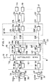
- symbols 1A-1F indicate plural hydraulic actuators of the hydraulic machine.
- these hydraulic actuators 1A-1F are a boom cylinder, an arm cylinder, a bucket cylinder, a swivel motor, and left-hand and right-hand travelling motors.
- control valves 2A-2F Connected to individual hydraulic circuits of these hydraulic actuators 1A-1F are control valves 2A-2F, each of which serves to control the flow rate and direction of a working fluid.
- the control valves 2A-2F constitute parts of the drive control system for the hydraulic machine. By controlling the control valves 2A-2F, their corresponding hydraulic actuators 1A-1F are actuated under control.
- the drive control system including the control valves 2A-2F has plural electric lever devices 3A-3F for the plural hydraulic actuators 1A-1F.
- the electric lever device 3A is provided with a manipulation lever 4A and an output device (for example, a potentiometer) 5A for generating an electrical manipulation signal corresponding to the degree and direction of each manipulation of the lever 4A.
- the electric lever devices 3B-3F are constructed similarly. Manipulation signals, which have been produced separately by the potentiometers 5A-5F of the electric lever devices 3A-3F, are fed to a controller unit 6.
- the controller unit 6 includes input devices, namely, A/D converters 8A-8F for receiving the manipulation signals from the potentiometers 5A-5F via signal conductors 7A-7F and converting the analog quantities of the manipulation signals to digital quantities respectively; a main controller 10 composed of a microcomputer and adapted to receive digital signals from the A/D converters 8A-8F via signal conductors 9A-9F and to compute control signals for the control valves 2A-2F, which control signals correspond of the respective manipulation signals of the electric lever devices 3A-3F; and output devices 12A-12F having, as built-in elements, D/A converters for receiving the control signals computed by the main controller 10 via respective signal conductors 11a-11F and converting the digital quantities of the control signals to analog quantities and unillustrated driver circuits for amplifying the thus-converted analog signals to produce electric actuation signals.
- input devices namely, A/D converters 8A-8F for receiving the manipulation signals from the potentiometers 5A-5F via signal conductors 7A-7
- a main power supply 13 is connected to the controller unit 6.
- the controller unit 6 includes a power supply 15 for the main controller 10 and another power supply 16 for the output devices 12A-12F.
- the power supplies 15,16 are connected to the main power supply 13 via a common power line 14 so as to control the voltage of the main power supply 13 to desired voltages respectively.
- the power supply 15 for the main controller 10 is connected to the main controller 10 via a power line 17, so that the main controller 10 is turned on.
- the power supply 16 for the output devices 12A-12F is connected to the driver circuits of the output devices 12A-12F by way of corresponding power lines 18A-18F. Incidentally, it is assumed that the voltage of the main power supply 13 can be applied, as is, to the output devices 12A-12F in the illustrated embodiment.
- the power supply 16 for the output devices 12A-12F is therefore composed as a mere power line.
- the driver circuits of the output devices 12A-12F are connected to the earth or ground 21 by way of their respective earth or ground lines 19A-19F and a common earth or ground line 20.
- control valves 2A-2F may be either solenoid-controlled valves equipped with a solenoid, or hydraulically-operated valves equipped with a hydraulic pilot. Where the control valves 2A-2F are solenoid-controlled valves, the electrical actuation signals produced respectively by the output devices 12A-12F are outputted directly to the solenoids of the corresponding control valves 2A-2F via corresponding signal conductors 22A-22F.
- the drive control system is equipped additionally with E/H converters 23A-23F for converting the electric actuation signals from the corresponding output devices 12A-12F of the control unit 6 to hydraulic actuation signals, a hydraulic pressure source 24, and hydraulic pressure lines 26A-26F connecting the hydraulic pressure source 24 to the respective E/H converters via a common hydraulic pressure line 25.
- the electric actuation signals produced respectively by the output devices 12A-12F are delivered to unillustrated solenoids of the corresponding E/H converters 23A-23F, where the electric actuation signals are converted to hydraulic actuation signals.
- the hydraulic actuation signals are then outputted to the corresponding control valves 2A-2F via signal lines 27A-27F.
- Said corresponding one of the control valves 2A-2F may hence take an actuated position different from the center valve position even after the corresponding one of the manipulation levers 4A-4F has been shifted back to the prescribed neutral position. Accordingly, the corresponding one of the hydraulic actuators 1A-1F and the working member driven by the hydraulic actuator may not take their initial positions corresponding to the neutral position of the corresponding manipulation lever, leading to the problem that the safety of work cannot be assured. According to the first embodiment, this problem can however be solved by the following construction.
- the drive control system further includes neutral position sensing means 30A-30F provided respectively with the electric lever devices 3A-3F and adapted to sense the neutral positions of the manipulation levers 4A-4F and an inhibition means 31 for receiving signals outputted from the neutral position sensing devices 30A-30F and when the manipulation levers 4A-4F are at their neutral positions, inhibiting the transmission of signals between the main controller 10 of the controller unit 6 and the control valves 2A-2F.
- the inhibition means 31 is constructed of plural cut-off devices 31A-31F which receive signals outputted from the corresponding neutral position sensing devices 30A-30F.
- the individual cut-off devices are designed in such a way that the transmission of electrical signals between the main controller 10 of the controller unit 6 and the corresponding control valves 2A-2F is inhibited while the signals outputted from the corresponding neutral position sensing devices 30A-30F indicate that the manipulation levers 4A-4F are at their neutral positions.
- the cut-off devices 31A-31F are provided respectively at locations appropriate to cut off the power lines 18A-18F of the output devices 12A-12F.
- the neutral position sensing devices 30A-30F may each be constructed, for example, of a limit switch or a switch formed of a conductor and a slider, as will be described subsequently.
- Each of the cut-off devices 31A-31F may be constructed, for example, of a switching circuit composed of an electronic device such as a transistor or an electromagnetic switch composed of a coil and make-break contacts, as will also be described subsequently.
- the cut-off devices 31A-31F are provided corresponding to the plural manipulation levers 4A-4F.
- the cut-off device corresponding to the manipulation lever returned to the neutral position is actuated to cause the corresponding control valve to return surely to its neutral position whether the other manipulation levers are at their neutral positions or not. It is hence possible to prevent the actuation of each control valve by a false signal independently of the manipulation levers of the other control valves, whereby the safety of each hydraulic actuator is ensured independently of the other hydraulic actuators.
- the other control systems for example, the output devices 12B-12F of the controller units of the control systems for the hydraulic actuators 1B-1F can be actuated upon manipulation of the manipulation levers 4B-4F of the corresponding electric lever devices 3B-3F.
- the other control systems can therefore function effectively. It is hence possible to perform temporary or necessary work by using control systems other than a control system that has developed trouble. This is certainly convenient.
- the above-described hydraulic machine is a hydraulic shovel and a problem has occurred in the control system for the bucket.
- the other control systems for the boom, arm and the like can still function even when the manipulation lever for the bucket is at the neutral position. It is hence still possible to perform bucketing temporarily by using the boom or arm. Even when trouble has occurred in the control system for a front attachment, the control systems for the travelling motors are still operable so that the hydraulic shovel can be driven to a repair site by the travelling motors.
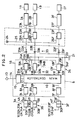
- FIG. 2 in which members equal or equivalent to those shown in FIG. 1 are identified by like reference symbols.
- the cut-off devices 31A-31F are provided at the locations appropriate to cut off the power lines 18A-18F of the output devices 12A-12F. These locations are however merely illustrative. Similar effects can also be obtained even when the cut-off devices are provided at other locations.
- FIG. 2 illustrates such embodiments.
- three embodiments in which the cut-off devices are provided at different locations are shown collectively in FIG. 2.
- One of the three embodiments is called “the second embodiment", while the other two embodiments are called “modifications of the second embodiment".
- an inhibition means 32 is constructed of plural cut-off devices 32A-32F provided respectively at locations appropriate to cut-off the signal conductors 11A-11F between the main controller 10 and the output devices 12A-12F.
- an inhibition means 33 is composed of plural cut-off devices 33A-33F provided respectively at locations appropriate to cut-off the signal conductors 22A-22F between the output devices 12A-12F and the control valves 2A-2F.
- an inhibition means 34 is constructed of plural cut-off devices 34A-34F provided respectively at locations appropriate to cut-off the earth or ground lines 19A-19F of the output devices 12A-12F.
- the electrical connections between the main controller 10 and the output devices 12A-12F are cut off when the corresponding manipulation levers 4A-4F are shifted back to their neutral positions. Even when a false signal occurs in the main controller 10 of the controller unit 6 or in any one of the electrical equipment arranged upstream of the main controller 10, the false signal is not transmitted to the output devices 12A-12F so that no actuation signal is produced. As in the first embodiment depicted in FIG. 1, the actuation of each control valve by a false signal is hence prevented independently of the manipulation levers of the other control valves so that the safety of each hydraulic actuator is ensured independently of the other hydraulic actuators.
- the electrical connections between the output devices 12A-12F and their corresponding control valves 2A-2F are cut off when the corresponding manipulation levers 4A-4F are shifted back to their neutral positions. Even when a false signal occurs in the controller unit 6 or in any one of the electrical equipment arranged upstream of the controller unit 6, no actuation signal is transmitted responsive to the false signal from the output devices 12A-12F to the E/H converters 23A-23F or control valves 2A-2F.
- the actuation of each control valve by a false signal is hence prevented independently of the manipulation levers of the other control valves so that the safety of each hydraulic actuator is ensured independently of the other hydraulic actuators.
- the electrical connections between the output devices 12A-12F and the earth or ground 21 are cut off when the corresponding manipulation levers 4A-4F are shifted back to their neutral positions.
- the output devices 12A-12F are rendered inoperative.
- a false signal occurs in the controller unit 6 or any one of the electrical equipment arranged upstream of the controller unit 6, no actuation signal is produced responsive to the false signal.
- the actuation of each control valve by a false signal is hence prevented independently of the manipulation levers of the other control valves so that the safety of each hydraulic actuator is ensured independently of the other hydraulic actuators.
- each control system is also ensured independently of the other control system like the first embodiment illustrated in FIG. 1.
- the control systems other than the troubled control system can function effectively. It is hence possible to perform temporary or necessary work by using the remaining control systems.
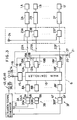
- FIG. 3 in which members equal to or equivalent to those shown in FIG. 1 are identified by like reference symbols.
- the inhibition means is constructed of plural cut-off devices.
- the inhibition means may however be constructed of a single cut-off device.
- FIG. 3 illustrates such embodiments.
- three embodiments in which the cut-off device is provided at different locations are shown collectively in FIG. 3.
- One of the three embodiments is called “the third embodiment", while the other two embodiments are called “modifications of the third embodiment”.
- the drive control system has an inhibition means 43.
- the inhibition means 43 is constructed of an actuation signal generator 44 - which receives neutral signals outputted respectively from the neutral position sensing devices 30A-30F and when all neutral signals have been inputted, outputs an actuation signal - and a single cut-off device 35 for receiving the actuation signal from the generator 44.
- the cut-off device 35 is provided at a location appropriate to cut off the power line 14 common to the power supply 15 for the main controller and the power supply 16 for the output devices.
- the main controller 10 and output devices 12A-12F are rendered inoperative so that the transmission of electrical signals between the output devices 12A-12F and their corresponding control valves 2A-2F is inhibited.
- a false signal is hence generated as described above, no actuation signal is outputted based on the false signal to the control valves 2A-2F, provided that the manipulation levers 4A-4F are all shifted back to their neutral positions.
- the control valves return to their central valve positions and the hydraulic actuators 1A-1F and the working members driven by the hydraulic actuators 1A-1F also return to their respective initial positions. Safety is hence ensured.
- the actuation signal generator 44 of the inhibition means 43 may be constructed of an AND circuit which receives each neutral signal as a high level signal and when all high level signals have been inputted, outputs a high level signal as an actuation signal.
- the drive control system has an inhibition means 45.
- the inhibition means 45 is provided, instead of the cut-off device 35 described above, with a single cut-off device 36 provided at a location appropriate to cut off the power supply 16 for the output devices.
- the drive control system has an inhibition means 46.
- the inhibition means 46 is provided, in place of the cut-off device described above, with a single cut-off device 37 arranged at a location appropriate to cut off the earth or ground line 20 common to the output devices 12A-12F.
- the electrical connections between the main power supply 13 and the output devices 12A-12F are collectively cut off when the corresponding manipulation levers 4A-4F are shifted back to their neutral positions. Even when a false signal occurs in the controller unit 6 or any one of the electrical equipment arranged upstream of the controller unit 6, no actuation signal is produced responsive to the false signal so that safety is ensured.
- the electrical connections between the output devices 12A-12F and the earth or ground 21 are collectively cut off when the corresponding manipulation levers 4A-4F are shifted back to their neutral positions. Even when a false signal occurs in the controller unit 6 or any one of the electrical equipment arranged upstream of the controller unit 6, no actuation signal is produced responsive to the false signal so that safety is ensured.
- cut-off devices 32A-32F, 33A-33F and 34A-34F of the second embodiment and its modifications shown respectively in FIG. 2, as well as the cut-off devices 35-37 of the third embodiment and its modifications depicted in FIG. 3 may each be constructed, for example, by a switching circuit formed of an electronic device such as a transistor or the like, or by an electromagnetic switch formed of a coil and make-break contacts, like the cut-off devices 31A-31F.
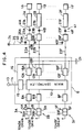
- FIG. 4 in which members equal to or equivalent to those shown in FIG. 1 are identified by like reference symbols.
- the inhibition means inhibits the transmission of electrical signal or signals.
- the inhibition means may be designed to inhibit the transmission of a hydraulic signal or signals.
- FIG. 4 illustrates such embodiments.
- the cut-off devices are provided at different locations are also shown collectively in FIG. 4.
- One of the two embodiments is called “the fourth embodiment", while the other embodiment is called “modification of the fourth embodiment”.
- the drive control system is equipped with an inhibition means 40 for inhibiting the transmission of hydraulic actuation signals between the E/H converters 23A-23F and their corresponding control valves 2A-2F.
- the inhibition means 40 is constructed of plural cut-off devices 40A-40F which receive signals outputted respectively from the neutral position sensing devices 30A-30F.
- the individual cut-off devices inhibit the transmission of hydraulic actuation signals between the E/H converters 23A-23F and their corresponding control valves 2A-2F while the corresponding signals outputted from the neutral position sensing devices 30A-30F indicate that the corresponding manipulation levers 4A-4F are at their neutral positions.
- the cut-off devices 40A-40F are provided at locations appropriate to cut off the hydraulic pressure lines 26A-26F of the E/H converters 23A-23F.
- the cut-off devices 40A-40F may each be constructed, for example, of a solenoid-operated changeover valve as will be described subsequently.
- the neutral signal of the neutral position sensing device 30 is inputted to the cut-off device 40A so that the cut-off device 40A is actuated to cut off the hydraulic connection between the hydraulic pressure source 24 and the E/H converter 23A.
- the E/H converter 23A is rendered inoperative.
- the drive control system has an inhibition means 41.
- the inhibition means 41 is constructed of cut-off devices 41A-41F provided at locations appropriate to cut off the signal lines 27A-27F between the E/H converters 23A-23F and their corresponding control valves 2A-2F.
- the drive control system is equipped with an inhibition means 47.
- the inhibition means 47 includes the above-mentioned actuation signal generator 44 - which receives signals outputted respectively from the neutral position sensing devices 30A-30F, and, when all neutral signals have been inputted, outputs an actuation signal - and a single cut-off device 42 for receiving the actuation signal from the generator 44. While all the signals outputted respectively from the neutral position sensing devices 30A-30F indicate that the corresponding manipulation levers 4A-4F are at their neutral positions, the inhibition means 47 inhibits collectively the transmission of hydraulic signals between the E/H converters 23A-23F and their corresponding control valves 2A-2F.
- the cut-off device 42 is provided at a location appropriate to cut off the common hydraulic pressure line 25 between the hydraulic pressure source 24 and the E/H converters 23A-23F.
- the neutral signals for the neutral position sensing devices 30A-30F are all inputted to the actuation signal generator 44 so that an actuation signal is inputted to the cut-off device 42 from the generator 44.
- the cut-off device 42 is therefore actuated, whereby the hydraulic connections between the hydraulic pressure source 24 and the individual E/H converters 23A-23F are cut off collectively. As a consequence, the E/H converters 23A-23F are rendered inoperative.
- the fifth embodiment assures the safety of work and requires the provision of only one cut-off device.
- the fifth embodiment has hence simplified the structure.
- the cut-off device 42 of the fifth embodiment shown in FIG. 5 may be constructed of a solenoid-operated changeover valve by way of example.
- the sixth embodiment of this invention will next be described with reference to FIG. 6.
- the sixth embodiment is similar to the first modification shown in FIG. 2 and equipped with the inhibition means 33, except that one of the manipulation lever-to-hydraulic actuator systems has been specified further.
- numeral 70 indicates a power source such as an engine.
- a hydraulic pump 71 and a pilot pump 72 Connected to the power source 70 are a hydraulic pump 71 and a pilot pump 72.
- the hydraulic pump 71 feeds a working fluid to a hydraulic cylinder 73 so as to drive the hydraulic cylinder 73.
- a control valve 74 is interposed between the hydraulic pump 71 and hydraulic cylinder 73.
- the control valve 74 can be changed over to a center valve position, a right-hand position or a left-hand position as shown in the drawing. By this change-over, the control valve 74 controls the actuation of the hydraulic cylinder 73.
- the control valve 74 is a hydraulic pilot-operated valve. Hydraulic pilot-operating devices 75A,75B are provided at both ends of the control valve 74.
- the hydraulic pilot-operating devices 75A,75B are connected to the pilot pump 72 by way of their corresponding solenoids 76A,76B of the E/H converter.
- a pilot pressure is applied to or removed from the hydraulic pilot-operating devices 75A,75B by energizing or deenergizing the solenoids 76A,76B of the E/H converter, so that the control valve 74 is changed over.
- the drive control system including the control valve 74 is equipped with an electric lever device 77 for the hydraulic cylinder 73.
- the electric lever device 77 has a manipulation lever 78 and an output device 78 which outputs an actuation signal corresponding to the degree and direction of each manipulation of the manipulation lever 78.
- the actuation signal is then inputted to a controller unit 80.
- the controller unit 80 is constructed of a microcomputer like the first embodiment depicted in FIG. 1. Specifically, the controller unit 80 has an input device, a main controller and an output device and also includes, as built-in elements, a power supply for the main controller and another power supply for the output device. Both power supplies are connected to an unillustrated power supply.
- an electric actuation signal corresponding to the manipulation signal is produced for the control valve 75.
- the actuation signal is outputted to the solenoids 76A,76B of the E/H converter by way of signal conductors 81,82 so as to energize the solenoids.
- Numeral 83 indicates a reservoir.
- the electric lever device 77 also has a neutral position sensing device 90 for sensing that the manipulation lever 78 is at its neutral position.
- the neutral position sensing device 90 may be constructed, for example, of a limit switch which is closed while the manipulation lever 78 is at the neutral position.
- a power supply 91 is connected to the neutral position sensing device 90.
- An electromagnetic switch 92 is interposed, as a cut-off device making up an inhibition means, in the signal conductors 81,82 which extend between the controller unit 80 and the solenoids 76A,76B respectively.
- the electromagnetic switch 92 is composed of a coil 93 connected to the power supply 91 via the neutral position sensing device 90 and make-break contacts 94A,94B which are turned on upon energization of the coil 93.
- the neutral position sensing device 90 does not operate.
- the limit switch is in an open state so that the power supply 91 and the coil 93 of the electromagnetic switch 92 are not connected to each other.
- the make-break contacts 94A,94B are hence in a closed state, whereby the solenoids 76A,76B of the E/H converter and the controller unit 89 are connected and the actuation of the hydraulic cylinder 73 is performed as usual.
- the neutral position sensing device 90 When the manipulation lever 78 has been shifted to the neutral position on the other hand, the neutral position sensing device 90 is actuated and where a limit switch is used, the limit switch is hence closed. Accordingly, the coil 93 of the electromagnetic switch 92 is energized to open the make-break contacts 94A,94B. The signal conductors 81,82 between the controller unit 89 and solenoids 76A,76B are hence cut off, whereby the solenoids 76A,76B are both deenergized to hold the control valve at the center valve position.
- the signal conductors between the controller unit 80 and the solenoids 76A,76B of the E/H converter are always cut off in the sixth embodiment when the manipulation lever is at the neutral position. Even when trouble occurs in the controller unit 80 or in any one of the electrical equipment arranged upstream of the controller unit 80, the control valve can hence be maintained at the center valve position whenever the manipulation lever is at the neutral position. It is accordingly possible to prevent any actuation of the hydraulic cylinder which is not intended by an operator, so that potential danger can be avoided.
- the drive control system according to the seventh embodiment of this invention will hereinafter be described with reference to FIG. 7.
- the first modification shown in FIG. 2 and equipped with the inhibition means 33 has been specified further in the seventh embodiment.
- the seventh embodiment includes plural manipulation lever-to-hydraulic actuator systems and employs solenoid-controlled valves as control valves. Members either equal to or equivalent to those shown in FIG. 6 are identified by like reference symbols.
- the electric lever devices 77A,77B have manipulation levers 78A,78B, output devices 79A,79B and neutral position sensing devices, for example, limit switches 90A,90B, respectively.
- the output devices 79A,79B are constructed as potentiometers.
- Two control valves 74A,74B are provided corresponding to the two hydraulic cylinders 73A,73B.
- the control valves 74A,74B are different in type from the control valve 74 depicted in FIG. 6. Namely, the control valves 74A,74B are solenoid-operated valves equipped with single solenoids 95A,95B respectively. By feeding currents, which are different in both amplitude and direction, to the solenoids 95A,95B, the switching of the control valves 74A,74B is controlled. Actuation signals produced at the controller unit 80 in response to manipulation signals from the electric lever devices 77A,77B are fed to the solenoids 95A,95B via signal conductors 96A,96B respectively.
- Electromagnetic switches 97A,97B are interposed as cut-off devices making up inhibition means respectively, in the respective signal conductors 96A,96B.
- the electromagnetic switches 97A,97B are constructed respectively of coils 98A,98B connected to the neutral position sensing devices 90A,90B, and make-break contacts 99A,99B connected to the signal conductors 96A,96B.
- the limit switch 90A is kept open so that the coil 98A of the electromagnetic switch 97A is maintained in a deenergized state.
- the make-break contact 99A is therefore in a closed state and the controller unit 80 and solenoid 95A are connected.
- the actuation of the hydraulic cylinder 73A can therefore be performed as usual.
- FIG. 8 the drive control system according to the eighth embodiment of this invention will next be described with reference to FIG. 8.
- the fifth embodiment shown in FIG. 5 and equipped with the inhibition means 47 has been specified further.
- members either equal to or equivalent to those depicted in FIGS. 6 and 7 are identified by like reference symbols.
- two systems of hydraulic cylinder 73A,73B-to-electric lever devices 100A,100B are also energized.
- the electric lever devices 100A,100B are equipped with the manipulation levers 78A,78B, the output devices 79A,79B and neutral position sensing devices 101A,101B respectively.
- the neutral position sensing devices 101A,101B are designed to output high-level signals when their corresponding manipulation levers 78A,78B have been shifted to their neutral positions.
- Control valves 102A,102B are of the same type as the control valve 74 shown in FIG. 6. Specifically, the control valves 102A,102B are both hydraulic pilot-operated valves and are provided at both their ends with hydraulic pilot-operating devices 103A,103B and 104A,104B respectively.
- the hydraulic pilot-operating devices 103A,103B and 104A,104B are connected to the pilot pump 72 by way of solenoids 105A,105B and 106A,106B of their corresponding E/H converters and their corresponding pilot circuits composed of hydraulic pressure lines 107A,107B and a common hydraulic pressure line 108 respectively.
- Actuation signals produced at the controller 80 in response to manipulation signals from the electric lever devices 78A,78B are fed to the solenoids 105A,105B and 106A,106B.
- a solenoid-operated changeover valve 109 is interposed as a cut-off device of an inhibition means in the common hydraulic line 108 of the pilot circuits.
- the changeover valve 109 is normally held at the left-hand position by a spring, so that the hydraulic pressure line 108 is maintained in a communicated state to establish communication with the pilot pump 72.
- the changeover valve 109 is switched to the right-hand position so that the hydraulic pressure line 108 is brought into communication with the reservoir 83.
- the neutral position sensing devices 101A,101B are connected to an AND circuit, while the AND circuit is connected to an amplification circuit 112 so that an actuation signal is outputted from the amplification circuit 112 to the solenoid 110 of the changeover valve 109.
- the AND circuit 111 and amplification circuit 112 make up an actuation signal generator.
- a manipulation signal is outputted from the output device 79A, an actuation signal is outputted responsive to the manipulation signal from the controller 80, and the solenoid 105A or 105B of the E/H converter is hence energized.
- the pilot pressure of the pilot pump 72 is applied to the hydraulic pilot-operating device 103A or 103B, whereby the control valve 102A is switched to actuate the hydraulic cylinder 73A in accordance with the manipulation of the manipulation lever 78A.
- the manipulation lever 78B is also manipulated in the same manner.
- the hydraulic cylinder 73B is hence actuated in accordance with the manipulation of the manipulation lever 78B.
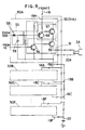
- cut-off devices 31A-31F shown in FIG. 1 are each constructed of a switching circuit formed of transistors.
- members either equal to or equivalent to those depicted in FIG. 1 are identified by like reference symbols.
- symbols 50A-50F indicate electric circuits provided corresponding to the control valves 2A-2F.
- the electric circuit 50A is constructed of an output circuit 51 corresponding to the driver circuit of the output device 12A, a cut-off circuit 52 corresponding to the cut-off device 31A, and a delay circuit 53 provided for a purpose to be described below.
- the output circuit 51 is an amplification circuit formed of first and second transistors 54,55. Inputted as a base current to the first transistor 54 is an analog signal which has been obtained by subjecting a control signal from the main controller 10 to D/A conversion. An amplified actuation signal is outputted from the collector of the second transistor 55 to the control valve 2A.
- the cut-off circuit 52 is a switching circuit formed of first and second transistors 56,57. While no neutral signal is fed from the neutral position sensing device 30A, the first transistor 56 is in an OFF state while the second transistor 57 is in an ON state. A current is therefore fed from the power supply 13 to the first and second transistors 54,55 of the output circuit, so that the transistors 54,55 are rendered conductive.
- the first transistor 56 When a neutral signal is inputted from the neutral position sensing device 30A to the base of the first transistor 56 via the delay circuit 53, the first transistor 56 is turned on while the second transistor 57 is turned off. As a result, the first and second transistors 54,55 of the output circuit 51 are rendered non-conductive, so that the output of an amplified signal from the output circuit 51 is inhibited.
- the delay circuit 53 is constructed of a reverse-current preventing diode 58 and a capacitor 59 adapted to set a delay time period. A neutral signal inputted in the capacitor 59 is prevented from reaching the cut-off circuit 52 by a predetermined time lag which corresponds to the capacity of the capacitor 59.
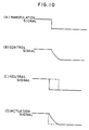
- the main controller 10 of the controller unit 6 subjects a manipulation signal from the potentiometer 5A of the electric lever device 3A to functional processing and then outputs the thus-processed value as a control signal.
- the wave form of the manipulation signal and that of the control signal are therefore not in conformity.
- the neutral signal changes stepwise at this time in response to the manipulation of the manipulation lever 4A as illustrated by a solid line in FIG. 10(C). If the neutral signal should be fed directly to the cut-off circuit 52, the actuation signal to be outputted from the output circuit 51 will change stepwise as indicated by a broken line in FIG. 10(D) so that a large shock will be produced on the working member.
- the delay circuit 53 and inputting the neutral signal with the predetermined time lag to the cut-off circuit 52 as illustrated by a broken line in FIG. 10(C) the actuation signal changes gradually with a waveform subjected to the functional processing like the control signal as indicated by a solid line in FIG. 10(D). It is hence possible to prevent the waveform of the control signal, which has been subjected to the functional processing, from being invalidated, so that smooth operation of the working member is realized.
- the electric circuits 50B-50F shown in FIG. 9 are constructed in the same manner as the electric circuit 50A.
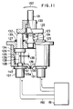
- numeral 120 designates a manipulation lever.
- the manipulation lever 120 is composed of a rod 121 and a presser plate 122 fixed integrally to the lower extremity of the rod 121 and having a lower surface formed into a slightly-curved surface.
- the lever 120 is supported on a support 124 by way of a universal joint 123 which allows the lever 120 to rotate over 360°.
- a thread is formed in the lower end portion of the support 124.
- the support 124 is screwed in an internally-threaded hole formed in a casing 126 which forms a main body, with a sealing 125 interposed between the support 124 and casing 126.
- the casing 126 is formed of an upper lid 127 and a box 128 onto which the upper lid 127 fits as an integral member.
- a recess 129 is formed in the lower part of the box 128.
- a bleeder 130 is formed in communication with the recess 129.
- a filter 131 is arranged inside the bleeder 130.
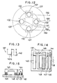
- Each pusher 132 which are movable linearly, are arranged in such a way that the pushers 132 are in contact with the lower surface of the presser plate 122 of the manipulation lever 120 and as shown in FIG. 12, the pushers 132 surround the rod 121 (not shown in FIG. 12) of the lever 120.
- the pushers 132 are provided to extend through the upper lid 127 and their corresponding sealings 133.
- Each pusher 132 has a large-diameter portion 134 at the lower end thereof and a projection 135 extending downwardly from the large-diameter portion 134.
- the large-diameter portion 135 of the pusher 132 can be brought into contact with the upper lid 127, so that the upper lid 127 serves as a limiting member for limiting the movement of the pusher 132 toward the lever 120.
- a spring 136 is provided inside the casing 126 to urge each pusher 132 toward the lever 120.
- One end of the spring 136 is maintained in engagement with the large-diameter portion 134 of the corresponding pusher 132, while the other end of the spring 136 is kept in engagement with the bottom wall of the box 128 of the casing 126.
- a linear stroke sensor 137 is arranged in opposition to each pusher 132.
- the sensor 137 is equipped, as built-in members, with an output device for outputting an electrical signal corresponding to the degree and direction of each manipulation of the manipulation lever 120 and a neutral position sensing device for sensing that the manipulation lever 120 is at its neutral position.
- the sensor 137 is arranged in such a way that an actuating pin 138 of the sensor 137 is located inside the casing 126.
- the pusher 132 and sensor 137 are arranged in such a way that a clearance 139 forming a zone insensitive to the lever 120 is left between the projection 135 of the pusher 132 and the actuating pin 138 of the sensor 137.
- a threaded portion 141 is formed in the inner wall of a guide portion 140 for guiding the actuating pin 138.
- Each sensor 137 is mounted on the casing 126 in such a way that a threaded portion 141 of the guide portion 140 is screwed in an internally-threaded hole formed in the box 128 of the casing 126 with a sealing 125a interposed between the sensor 137 and the bottom wall of the box 128.
- the threaded portion 141 of the guide portion 140 forms a means for making the dimension of the clearance 139 variable.
- each of the above-described sensors 137 is equipped with an electric circuit.
- the electric circuit has a switch 142 and a variable resistor 143.
- the switch 142 serves to sense that the manipulation lever is at its neutral position, while the variable resistor 143 outputs an electric signal corresponding to the degree of each manipulation of the manipulation lever.
- the internal structure of each sensor 137 is illustrated in FIG. 14 and FIG. 15. Specifically, each sensor 137 is provided integrally with the actuating pin 138 described above and is provided with sliders 144,145 movable up and down as viewed in FIG.
- a conductor 146 with which the slider 144 is always maintained in contact a conductor 147 with which the slider 144 and slider 145 are selectively brought into contact, a resistor 148 provided in continuation with the conductor 147, and a conductor 149 with which the slider 145 is always maintained in contact.
- the switch 142 depicted in FIG. 13 and described above is constructed by the conductors 146,147 and the slider 144.
- the variable resistor 143 shown in FIG. 13 is constructed by the conductor 147, resistor 148, conductor 149 and slider 145.
- each sensor 137 is connected to a control unit adapted to perform various signal processings, namely, to a controller unit 151 by way of a signal conductor 150 as illustrated in FIG. 11.
- the controller unit 151 is equipped with a main controller 152, a driver circuit 154 for outputting a signal for actuating a solenoid-operated valve 153 which controls the actuation of a hydraulic actuator for driving a working member of a hydraulic machine, and an electromagnetic switch 156 connected as a cut-off device to a power line 155 of the driver circuit 154.
- the coil of the electromagnetic switch 156 is connected to a switch 142 built in the sensor 137.
- the switch 142 When the switch 142 is closed, the coil of the electromagnetic switch 156 is energized to close its make-break contacts. The connection between the power supply and the driver circuit 154 is hence established. When the switch 142 is opened, the make-break contacts are opened to cut off the power line 155 of the driver circuit 154 so that the driver circuit 154 is rendered inoperative.
- the working member driven by the hydraulic actuator is a boom, arm, bucket, swivel cabin, etc. of a hydraulic shovel
- two opposing sensors 137 of the four sensors 137 form an output device for one working member. Therefore, the two opposing sensors 137 are both connected to the same control valve 153 by way of the controller unit 151.
- the switch 142 shown in FIG. 16 is turned on so that the electromagnetic switch 156 depicted in FIG. 16 is also turned on. In other words, the power line 155 is connected. Furthermore, the slider 145 is connected to the resistor 148 and conductor 149 so that an electrical signal corresponding to the degree of the manipulation of the lever 120 is outputted to the main controller 152 of the controller unit 151.
- a control signal corresponding to the electric signal is outputted from the main controller 152 to the driver circuit 154 and an actuation signal is then outputted from the driver circuit 154 to the actuation portion of the solenoid-controlled valve 153, whereby an unillustrated hydraulic actuator is actuated so that an associated working member is driven in accordance with the degree of the manipulation of the manipulation lever 120.
- the pusher 132 When the manipulation lever 120 has been shifted back to the initial neutral position, the pusher 132 is allowed to move upward by the return force of the spring 136 shown in FIG. 11 to a position where the large-diameter portion 134 of the pusher 132 is limited by the upper lid 127 of the casing 126. Concurrently with the upward movement of the pusher 132, the actuating pin 138 of the sensor 137 also moves upwards to the position shown in FIG. 11, so that the sliders 144,145 illustrated in FIG. 14 take such a positional relation as shown in FIG. 14. Namely, the slider 145 is separated from the resistor 148 first of all. The slider 144 is then separated from the conductor 147, whereby the switch 142 is turned on.
- the clearance 139 forms an insensitive zone for the rotation of the lever 120.
- the clearance 139 can easily be adjusted to a desired value.
- the insensitive zone can be adjusted to any desired value with ease.
- each pusher 132 always remains at the same position limited by the upper lid 127 of the casing 126, namely, by the limiting member. It is hence possible to obtain stable operability without forming a hysteresis loop by the manipulation and subsequent return of the manipulation lever unlike the conventional gear engagement with its accompanying rattle, so that stable operability is obtained.
- the drive of these two working members can be used so that the size of the system can be reduced.
- Each sensor 137 is equipped with the switch 142 for sensing that the manipulation lever 120 is at its neutral position. Even when trouble or jamming caused by noise occurs in the signal system including the controller unit 151, the power line 155 is cut off as described above whenever the manipulation lever 120 is shifted to the neutral position. Accordingly, the actuation of the driver circuit 154 is stopped, the control valve 152 is allowed to return to the center valve position, and the corresponding working member is brought into a state corresponding to the neutral state of the manipulation lever 120. Excellent safety is also exhibited in this regard.
- the bleeder 13 is formed through the casing 126 as described above, the internal pressure of the casing 126 is maintained constant irrespective of the movement of the pushers 132 so that the sensors 137, sealings 125,125a,133 and the like are kept free from undue loads and hence have superb durability.
- the recess 129 is formed in the box 128 of the casing 126. Even when dew forms inside the casing 126 due to variations in the surrounding temperature or the like, the dewdrops collect in the recess 129 and are allowed to flow out through the filter 131. The sensors 137 can hence be protected from dew.
- each sensor 160 has a switch 161 and variable resistor 162 arranged in a different fashion from those provided in the electric circuit depicted in FIG. 13.
- the internal structure of the sensor 160 is illustrated in FIGS. 18 and 19. Specifically, the sensor 160 has sliders 163,164 provided integrally with the actuating pin 138 described above and movable up and down as viewed in FIG.
- a conductor 165 with which the slider 163 is selectively brought into contact a conductor 167 with which the slider 163 is always maintained in contact, a conductor 167 with which the slider 164 is selectively brought into contact, a conductor 168 with which the slider 164 is always maintained in contact, and a resistor 169 with which the slider 164 is selectively brought into contact.
- the resistor 169 is provided in continuation with the conductors 166,167.
- the switch 161 shown in FIG. 17 is formed by the conductors 165,166 and slider 163, while the variable resistor 162 depicted in FIG. 17 is formed by the conductor 167, resistor 169, conductor 168 and slider 164.
- the above-described electric lever device is constructed to transmit each stroke of the manipulation lever as movements of the pushers to the corresponding linear stroke sensors, it is possible to output an electric signal corresponding to the stroke of the manipulation lever without need for interposition of any gear engagement. It is hence possible to avoid the occurrence of a hysteresis loop which occurs when a gear engagement is interposed and also to to set up a desired insensitive zone, thereby obtaining superb operability and safety compared with conventional electric lever devices.
- the electric lever device can also be used suitably to drive plural working members.
- the device can be constructed smaller than conventional electric lever devices.
- a switch is provided to sense that the manipulation lever is at its neutral position. Even when trouble or jamming caused by noise occurs in a signal system to which linear stroke sensors are connected, a signal corresponding to the neutral position is outputted from the switch so long as the manipulation lever is shifted back to the neutral position. It is hence possible to make the associated working member return to the initial state on the basis of the signal. Hence, excellent safety is also assured in this regard.
- each cut-off device of the inhibition means was described as a device adapted to cut off the transmission of a current or hydraulic pressure in an ON/OFF manner.
- the cut-off device should however be not interpreted as being limited to such a device.
- Each cut-off device may be designed to reduce the current or hydraulic pressure, which is to be transmitted to an output device of a controller unit, an E/H converter or a control valve, to a level insufficient to actuate the output device, E/H converter or control device. It will be understood easily that similar effects can be achieved by such a cut-off device.
- inhibitor as used herein should therefore be interpreted in a broad sense so as to include not only “100% cut-off” but also "reduction to a level insufficient to actuate an output device, E/H converter, control device or the like".
Landscapes
- Engineering & Computer Science (AREA)
- Physics & Mathematics (AREA)
- Human Computer Interaction (AREA)
- Manufacturing & Machinery (AREA)
- General Physics & Mathematics (AREA)
- Automation & Control Theory (AREA)
- Fluid Mechanics (AREA)
- Mechanical Engineering (AREA)
- General Engineering & Computer Science (AREA)
- Operation Control Of Excavators (AREA)
- Fluid-Pressure Circuits (AREA)
Description
- This invention relates to a drive control system for a hydraulic machine, specifically, to a drive control system equipped with an electric lever device for controlling the hydraulic actuator of a machine such as a hydraulic shovel.
- A machine such as a hydraulic shovel is generally equipped with plural hydraulic actuators. These hydraulic actuators are individually controlled by corresponding actuation control devices which include a manipulation lever device. Specific examples of the actuation control device may include those making use of an electric lever device. Such an electric lever device has a manipulation lever and an output device for generating an electrical manipulation signal corresponding to the degree of manipulation of the lever (for example, a potentiometer), a control valve connected to a hydraulic circuit for actuating a hydraulic actuator, a controller unit having a main controller for receiving the manipulation signal from the electric lever device and computing a control signal for the control valve on the basis of the manipulation signal, and an output device for generating an electrical actuation signal corresponding to the control signal. A main power supply is also provided to drive the controller unit. The controller unit includes a power supply for the main controller and another power supply for the output device. The power supplies are both connected to the main power supply. For plural hydraulic actuators, the corresponding number of control valves, electric lever devices, and output devices of the controller unit are provided.
- In such a drive control device, the controller unit is brought into a driven state upon connection of the main controller's power supply and the power supply for the output devices to the main power supply. When the manipulation lever is moved in a given degree from the neutral position, an electrical signal corresponding to the degree of manipulation of the lever is outputted from the potentiometer to the controller unit so that an electrical actuation signal corresponding to the manipulation signal is produced by the main controller and output device of the controller unit. Where the control valve is a solenoid-operated valve, the solenoid-operated valve is actuated directly by the actuation signal. Where the control valve is a hydraulic pilot-operated valve, the electrical actuation signal is converted to a hydraulic signal by an electrical signal/hydraulic signal converter to actuate the hydraulic pilot-operated valve. In response to the actuation of the control valve, the hydraulic actuator is actuated to drive the working member with which the hydraulic actuator is associated.
- Where the hydraulic machine is a construction machine (for example, a hydraulic shovel for digging or excavating the earth), the above-mentioned hydraulic actuators are a boom cylinder, an arm cylinder, a bucket cylinder, a swivel motor, etc. The aforementioned working members include a boom driven by the boom cylinder, an arm driven by the arm cylinder, a bucket driven by the bucket cylinder, a swivel cabin driven by the swivel motor, etc.
- If a certain problem occurs or if work-induced noise causes jamming in the controller unit, a signal conductor between the electric lever device and the controller unit, or the electric lever device of the above-described conventional drive control system, a false signal may be outputted from the output device of the controller unit to the control valve so that even after the manipulation lever has been shifted back to the neutral position, the control valve takes an actuated position different from the center valve position. As a result, the associated hydraulic actuator and working member are not at their initial positions corresponding to the neutral position of the manipulation lever, leading to a possible safety hazard. Such problems tend to occur especially where a construction machine such as the above-mentioned hydraulic shovel is used, because its working environment is usually severe.
- DE A-2631530 discloses a drive control system equipped with an electric lever device in which the electric lever device is provided with a switch for sensing the neutral position of a manipulation lever. While the manipulation lever is at the neutral position, the switch is kept open so as to inhibit the actuation of a manipulation signal output device. Let's assume that such a problem, or noise jamming, has occurred in the electric lever device and a false signal is about to be outputted as a result. The above construction opens the switch when the manipulation lever is shifted back to the neutral position. The actuation of the output device is hence inhibited to avoid the output of the false signal. The safety of the work is hence ensured.
- However, in the conventional system described above, the prevention of a false signal occurring due to trouble, or jamming caused by noise or similar trouble is limited to the electric lever device. The conventional system cannot inhibit the output of a false signal when the false signal is produced due to occurrence of trouble, jamming caused by noise or similar trouble in a signal conductor downstream of the electric lever device or in the controller unit. Even when the manipulation lever is at the neutral position, the control valve is actuated to drive the associated hydraulic actuator and working member, resulting in the problem that safety cannot be assured.
- An object of this invention is therefore to provide a drive control system for a hydraulic machine, which even when a trouble, jamming caused by noise or similar trouble occurs at least in a main controller of a controller unit, an electric lever device, a signal conductor between the main controller of the controller unit and the electric lever device or control equipment, does not produce any false signal so long as the manipulation lever is at the neutral position, and safety of work is hence ensured.
- In order to achieve the above object, the present invention provides a drive control system for a hydraulic machine. The drive control system includes an electric lever device equipped with a manipulation lever and a first output means for generating an electrical manipulation signal corresponding to the degree of manipulation of the lever, a control valve connected to a hydraulic circuit adapted to actuate a hydraulic actuator, and a control means equipped with a main controller for receiving the manipulation signal and computing a control signal on the basis of the manipulation signal, and a second output means for receiving the control signal and generating an electrical actuation signal for the control valve corresponding to the control signal, the system additionally comprising a neutral position sensing means provided with the electric lever device and adapted to sense a neutral position of the manipulation lever, and an inhibition means which receives an output signal from the neutral position sensing means, and, when the manipulation lever is at the neutral position, inhibits the transmission of a signal between the main controller of the control means and the control valve.
- When the manipulation lever of the electric lever device has been shifted back to the neutral position, the return of the manipulation lever to the neutral position is sensed by the neutral position sensing means. The inhibition means is then actuated by a signal from the neutral position sensing means, so that the transmission of a signal between the main controller of the control means and the control valve is inhibited. Even if a problem or jamming caused by work-induced noise occurs in an electric equipment including the main controller of the control means and a false signal is generated, the false signal is hence not transmitted to the control valve so that the control valve is allowed to return to the center valve position and the hydraulic actuator and the working member driven by the hydraulic actuator are both allowed to return to their initial positions. Safety is hence ensured.
- The above inhibition means may be of such a type that the transmission of an electrical signal between the main controller of the control means and the control valve is inhibited. Where the drive control system is equipped with an electric signal/hydraulic signal converter means for converting an electrical actuation signal from the output means of the control means to a hydraulic drive signal (hereinafter abbreviated as "E/H converter") and the control valve is a hydraulic pilot-operated control valve, the inhibition means may be of such a type that the transmission of a hydraulic signal between the E/H converter and the hydraulic pilot-operated control valve is inhibited.
- Where the inhibition means inhibits the transmission of an electrical signal between the main controller of the control means and the control valve, the drive control system may be provided additionally with a main power supply to actuate the control means; and the inhibition means may cut off an electrical connection between the main power supply and the control means. In a drive circuit for a hydraulic circuit having one power supply for the main controller and another for the output means, said power supplies being both connected to the main power supply, the inhibition means may cut off an electrical connection between the power supply for the output means and the output means. The inhibition means may also cut off an electrical connection between the output means of the control means and the control valve, an electrical connection between the main controller of the control means and the output means, and/or an electrical connection between the output means of the control means and an earth or ground.
- Where the inhibition means inhibits the transmission of a hydraulic signal between the E/H converter and the hydraulic pilot-operated control valve, the inhibition means may cut off the transmission of a hydraulic connection between a hydraulic pressure source for the E/H converter and the E/H converter, or a hydraulic connection between the E/H converter and the control valve.
- In a drive control system which is suitable for use in a hydraulic machine and is provided with a plurality of hydraulic actuators and hydraulic circuits of the same types as those described above and, further, with plural control valves, electric lever devices and output means of the control means, said valves, devices and output means being of the same types as the above-described valve, device and output means, in association with the respective hydraulic actuators and hydraulic circuits, the above-described neutral position sensing means is provided with each of the plural electric lever devices. The inhibition means may be constructed of a means which receives signals outputted from the individual neutral position sensing means and outputs an actuation signal when these signals all indicate that the corresponding manipulation levers are at their neutral positions respectively, and a single cut-off means for receiving the actuation signal and collectively inhibiting the transmission of signals between the main controller of the control means and the plural control valves.
- In this case, the transmission of electrical signals is collectively inhibited so long as all the manipulation levers are shifted back to their neutral positions. Safety is hence ensured. Since only one cut-off means is required, the structure can be simplified.
- The inhibition means may also be constructed of a plurality of cut-off devices adapted to receive signals outputted respectively from the corresponding plural neutral position sensing means. In this case, each cut-off means inhibits the transmission of a signal between the main controller of the control means and its corresponding control valve, while the signal outputted from the corresponding neutral position sensing means indicates that the corresponding manipulation lever is at the neutral position.
- When one of the manipulation levers has returned to the neutral position in the above case, the inhibition means corresponding to the manipulation lever which has returned to the neutral position is actuated to cause the corresponding control valve to return without fail to the neutral valve position whether the other manipulation levers are at their neutral positions or not. It is hence possible to prevent the actuation of each control valve by a false signal independently of the manipulation levers of the other control valves. This assures the safety of each hydraulic actuator independently.
- Where plural cut-off means are provided, they may cut off electrical connections between the power supply for the plural output means and the corresponding plural output means, electrical connections between the main controller and the corresponding plural output means, electrical connections between the corresponding plural output means and the corresponding plural control valves, or electrical connections between the corresponding plural output means and the earth. The plural cut-off means may also cut off hydraulic connections between the hydraulic pressure source and the corresponding plural E/H converters or hydraulic connections between the corresponding plural E/H converters and the corresponding plural hydraulic pilot-operated control valves.
- The above inhibition means may preferably be provided with a delay means for receiving a neutral signal from the neutral position sensing means before the neutral signal is inputted to the cut-off means.
- The provision of the delay means enables the input of the neutral signal to the cut-off means with a delay of a predetermined time period. It is hence possible to subject the neutral signal to functional processing at the main controller right after the manipulation lever has been shifted back to the neutral position, thereby avoiding the occurrence of shock on the corresponding working member.
- Each electric lever device may preferably be constructed of a movable pusher means responsive to each manipulation of the corresponding manipulation lever, a limiting means for limiting the movement of the pusher means toward the corresponding manipulation lever, a spring means biasing the pusher means toward the corresponding manipulation lever and a linear stroke sensor with which the pusher means is engageable. The corresponding output means and neutral position sensing means are constructed by the linear stroke sensor.
- Owing to the above construction, each manipulation of the manipulation lever is transmitted to the linear stroke sensor by way of a movement of the pusher means. When the manipulation lever returns to the neutral position, the pusher means is shifted by the force of the spring means to a position where any further movement of the pusher means is limited by the limiting means. It is hence possible to output an electrical signal corresponding to the degree of the manipulation of the manipulation lever without need for the interposition of any gear engagement, thereby making it possible to avoid the occurrence of a hysteresis loop which would occur when a gear engagement is interposed.
- Preferably, the manipulation lever may be supported turnably over 360° by a universal joint and the pusher means may comprise four pushers arranged around the manipulation lever. Since this construction allows the driving of plural pairs of pushers by a single manipulation lever to output an electrical signal from the corresponding linear stroke sensor, it can also be applied suitably for driving plural working members so that the system can be reduced in size.
- It is also preferable to arrange the pusher means and linear stroke sensor with a predetermined clearance left therebetween. Even when vibrations are transmitted during operation to the manipulation lever located at the neutral position, the clearance prevents the actuation of the linear stroke sensor and hence ensures excellent manipulation characteristics and safety.
- Each of the above electric lever devices may preferably have a casing in which the spring means and mutually opposing portions of the pusher means and linear stroke sensor are enclosed, and the casing defines a bleeder. Owing to the provision of the casing, the pressure is maintained constant inside the casing irrespective of movements of the pusher means and the sensor; seals and the like are kept free from undue loads, whereby excellent durability is assured.
-
- FIG. 1 is a simplified block diagram showing a drive control system according to a first embodiment of this invention, which is suitable for use in a hydraulic machine;
- FIG. 2 is a simplified block diagram showing drive control systems according to a second embodiment of this invention and its modifications, each of which is suitable for use in a hydraulic machine;
- FIG. 3 is a simplified block diagram showing drive control systems according to a third embodiment of this invention and its modifications, each of which is suitable for use in a hydraulic machine;
- FIG. 4 is a simplified block diagram showing drive control systems according to a fourth embodiment of this invention and its modifications, each of which is suitable for use in a hydraulic machine;
- FIG. 5 is a simplified block diagram showing a drive control system according to a fifth embodiment of this invention, which is suitable for use in a hydraulic machine;
- FIG. 6 is a simplified block diagram showing a drive control system according to a sixth embodiment of this invention, which is suitable for use in a hydraulic machine;
- FIG. 7 is a simplified block diagram showing a drive control system according to a seventh embodiment of this invention, which is suitable for use in a hydraulic machine;
- FIG. 8 is a simplified block diagram showing a drive control system according to an eighth embodiment of this invention, which is suitable for use in a hydraulic machine;
- FIG. 9 is a circuit diagram showing one example of a cut-off device of the drive control system illustrated in FIG. 1;
- FIGS. 10(A) through 10(D) are diagrammatic representations, to which reference will be made upon explanation of reasons for the provision of a delay circuit with the cut-off device depicted in FIG. 9;
- FIG. 11 is a side view of one example of an electric lever device, in which some elements are shown in cross-section;
- FIG. 12 is a plan view of the exemplary electric lever device, showing the arrangement of pushers;
- FIG. 13 is an electric circuit diagram of a linear stroke sensor provided with the electric lever device;
- FIG. 14 is a front view showing the internal structure of the linear stroke sensor which makes up the electric circuit;
- FIG. 15 is a side view of the linear stroke sensor;
- FIG. 16 is a circuit diagram showing the manner of connection among the linear stroke sensor, a controller unit, a cut-off device and a control valve;
- FIG. 17 illustrates another example of the electric circuit of the linear stroke sensor;
- FIG. 18 is a front view showing the internal structure of a linear stroke sensor which has materialized the electric circuit of FIG. 17; and
- FIG. 19 is a side view of the linear stroke sensor of FIG. 18.
- The drive control system according to the first embodiment of this invention, which is suitable for use in the hydraulic machine, will be described with reference to FIG. 1.
- In FIG. 1,
symbols 1A-1F indicate plural hydraulic actuators of the hydraulic machine. Where the hydraulic machine is a hydraulic shovel, thesehydraulic actuators 1A-1F are a boom cylinder, an arm cylinder, a bucket cylinder, a swivel motor, and left-hand and right-hand travelling motors. Connected to individual hydraulic circuits of thesehydraulic actuators 1A-1F arecontrol valves 2A-2F, each of which serves to control the flow rate and direction of a working fluid. Thecontrol valves 2A-2F constitute parts of the drive control system for the hydraulic machine. By controlling thecontrol valves 2A-2F, their correspondinghydraulic actuators 1A-1F are actuated under control. - The drive control system including the
control valves 2A-2F has pluralelectric lever devices 3A-3F for the pluralhydraulic actuators 1A-1F. Theelectric lever device 3A is provided with amanipulation lever 4A and an output device (for example, a potentiometer) 5A for generating an electrical manipulation signal corresponding to the degree and direction of each manipulation of thelever 4A. Theelectric lever devices 3B-3F are constructed similarly. Manipulation signals, which have been produced separately by thepotentiometers 5A-5F of theelectric lever devices 3A-3F, are fed to acontroller unit 6. Thecontroller unit 6 includes input devices, namely, A/D converters 8A-8F for receiving the manipulation signals from thepotentiometers 5A-5F viasignal conductors 7A-7F and converting the analog quantities of the manipulation signals to digital quantities respectively; amain controller 10 composed of a microcomputer and adapted to receive digital signals from the A/D converters 8A-8F viasignal conductors 9A-9F and to compute control signals for thecontrol valves 2A-2F, which control signals correspond of the respective manipulation signals of theelectric lever devices 3A-3F; andoutput devices 12A-12F having, as built-in elements, D/A converters for receiving the control signals computed by themain controller 10 via respective signal conductors 11a-11F and converting the digital quantities of the control signals to analog quantities and unillustrated driver circuits for amplifying the thus-converted analog signals to produce electric actuation signals. - A
main power supply 13 is connected to thecontroller unit 6. Thecontroller unit 6 includes apower supply 15 for themain controller 10 and anotherpower supply 16 for theoutput devices 12A-12F. The power supplies 15,16 are connected to themain power supply 13 via acommon power line 14 so as to control the voltage of themain power supply 13 to desired voltages respectively. Thepower supply 15 for themain controller 10 is connected to themain controller 10 via apower line 17, so that themain controller 10 is turned on. Thepower supply 16 for theoutput devices 12A-12F is connected to the driver circuits of theoutput devices 12A-12F by way ofcorresponding power lines 18A-18F. Incidentally, it is assumed that the voltage of themain power supply 13 can be applied, as is, to theoutput devices 12A-12F in the illustrated embodiment. Thepower supply 16 for theoutput devices 12A-12F is therefore composed as a mere power line. The driver circuits of theoutput devices 12A-12F are connected to the earth orground 21 by way of their respective earth orground lines 19A-19F and a common earth orground line 20. - In the first embodiment, the
control valves 2A-2F may be either solenoid-controlled valves equipped with a solenoid, or hydraulically-operated valves equipped with a hydraulic pilot. Where thecontrol valves 2A-2F are solenoid-controlled valves, the electrical actuation signals produced respectively by theoutput devices 12A-12F are outputted directly to the solenoids of thecorresponding control valves 2A-2F viacorresponding signal conductors 22A-22F. Where thecontrol valves 2A-2F are hydraulically-operated valves, the drive control system is equipped additionally with E/H converters 23A-23F for converting the electric actuation signals from thecorresponding output devices 12A-12F of thecontrol unit 6 to hydraulic actuation signals, ahydraulic pressure source 24, andhydraulic pressure lines 26A-26F connecting thehydraulic pressure source 24 to the respective E/H converters via a commonhydraulic pressure line 25. The electric actuation signals produced respectively by theoutput devices 12A-12F are delivered to unillustrated solenoids of the corresponding E/H converters 23A-23F, where the electric actuation signals are converted to hydraulic actuation signals. The hydraulic actuation signals are then outputted to thecorresponding control valves 2A-2F viasignal lines 27A-27F. - The general construction of the drive control system for the hydraulic machine has been described above. Let's now assume that a certain problem or jamming caused by work-induced noise has occurred in the
controller unit 6, one of thesignal conductors 7A-7F between theelectric lever devices 3A-3F and thecontroller unit 6 or one of theelectric lever devices 3A-3F and a false signal is produced accordingly. In a drive control system such as that described above, an actuation signal is then outputted on the basis of the false signal from one of theoutput devices 12A-12F of thecontroller unit 6 to the corresponding one of thecontrol valves 2A-2F as described above. Said corresponding one of thecontrol valves 2A-2F may hence take an actuated position different from the center valve position even after the corresponding one of the manipulation levers 4A-4F has been shifted back to the prescribed neutral position. Accordingly, the corresponding one of thehydraulic actuators 1A-1F and the working member driven by the hydraulic actuator may not take their initial positions corresponding to the neutral position of the corresponding manipulation lever, leading to the problem that the safety of work cannot be assured. According to the first embodiment, this problem can however be solved by the following construction. - The drive control system further includes neutral position sensing means 30A-30F provided respectively with the
electric lever devices 3A-3F and adapted to sense the neutral positions of the manipulation levers 4A-4F and an inhibition means 31 for receiving signals outputted from the neutralposition sensing devices 30A-30F and when the manipulation levers 4A-4F are at their neutral positions, inhibiting the transmission of signals between themain controller 10 of thecontroller unit 6 and thecontrol valves 2A-2F. The inhibition means 31 is constructed of plural cut-offdevices 31A-31F which receive signals outputted from the corresponding neutralposition sensing devices 30A-30F. The individual cut-off devices are designed in such a way that the transmission of electrical signals between themain controller 10 of thecontroller unit 6 and thecorresponding control valves 2A-2F is inhibited while the signals outputted from the corresponding neutralposition sensing devices 30A-30F indicate that the manipulation levers 4A-4F are at their neutral positions. In the first embodiment, the cut-offdevices 31A-31F are provided respectively at locations appropriate to cut off thepower lines 18A-18F of theoutput devices 12A-12F. - The neutral
position sensing devices 30A-30F may each be constructed, for example, of a limit switch or a switch formed of a conductor and a slider, as will be described subsequently. Each of the cut-offdevices 31A-31F may be constructed, for example, of a switching circuit composed of an electronic device such as a transistor or an electromagnetic switch composed of a coil and make-break contacts, as will also be described subsequently. - Let's now assume by way of example that the
manipulation lever 4A of theelectric lever device 3A has been shifted back to the neutral position in the first embodiment constructed as described above. The return of themanipulation lever 4A to the neutral position is then sensed by the neutralposition sensing device 30A to output a neutral signal. The neutral signal is then inputted to the cut-offdevice 31A. The cut-offdevice 31A is actuated by the neutral signal to cut-off the electrical connection between thepower supply 17 for the output devices and theoutput device 12A. As a result, the driver circuit of theoutput device 12A is brought into an inoperative state. Even when trouble or jamming caused by work-induced noise occurs in thecontroller unit 6 or any one of the electrical equipment provided upstream of the controller unit (namely, in one of theinput devices 8A-8F, themain controller 10, one of theoutput devices 12A-12F, or in one of the signal lines 7A-7F) and a false signal is hence generated as described above, no actuation signal is produced based on the false signal by theoutput device 12A, provided that themanipulation lever 4A is shifted back to the neutral position. Accordingly, the transmission of an electrical signal between themain controller 10 and thecontrol valve 2A is inhibited. As a result, thecontrol valve 2A returns to the central valve position and thehydraulic actuator 1A and the working member driven by thehydraulic actuator 1A also return to their respective initial positions. Safety is hence ensured. - When the manipulation levers 4B-4F are individually shifted back to their neutral positions, their corresponding cut-off
devices 31B-31F are actuated in the same manner so as to ensure safety. - In the first embodiment, the cut-off
devices 31A-31F are provided corresponding to the plural manipulation levers 4A-4F. When one of the manipulation levers has returned to the neutral position, the cut-off device corresponding to the manipulation lever returned to the neutral position is actuated to cause the corresponding control valve to return surely to its neutral position whether the other manipulation levers are at their neutral positions or not. It is hence possible to prevent the actuation of each control valve by a false signal independently of the manipulation levers of the other control valves, whereby the safety of each hydraulic actuator is ensured independently of the other hydraulic actuators. - Even when trouble has occurred in one of the control systems, for example, in the
output device 12A of the controller unit or an electrical equipment arranged upstream of theoutput device 12A in the control system for thehydraulic actuator 1A and themanipulation lever 4A of the correspondingelectric lever device 3A is held at the neutral position, the other control systems, for example, theoutput devices 12B-12F of the controller units of the control systems for thehydraulic actuators 1B-1F can be actuated upon manipulation of the manipulation levers 4B-4F of the correspondingelectric lever devices 3B-3F. The other control systems can therefore function effectively. It is hence possible to perform temporary or necessary work by using control systems other than a control system that has developed trouble. This is certainly convenient. Let's assume by way of example that the above-described hydraulic machine is a hydraulic shovel and a problem has occurred in the control system for the bucket. The other control systems for the boom, arm and the like can still function even when the manipulation lever for the bucket is at the neutral position. It is hence still possible to perform bucketing temporarily by using the boom or arm. Even when trouble has occurred in the control system for a front attachment, the control systems for the travelling motors are still operable so that the hydraulic shovel can be driven to a repair site by the travelling motors. - The second embodiment of this invention and its modifications will next be described with reference to FIG. 2, in which members equal or equivalent to those shown in FIG. 1 are identified by like reference symbols.
- In the first embodiment, the cut-off
devices 31A-31F are provided at the locations appropriate to cut off thepower lines 18A-18F of theoutput devices 12A-12F. These locations are however merely illustrative. Similar effects can also be obtained even when the cut-off devices are provided at other locations. FIG. 2 illustrates such embodiments. In order to avoid the inclusion of an unduly large number of drawing sheets, three embodiments in which the cut-off devices are provided at different locations are shown collectively in FIG. 2. One of the three embodiments is called "the second embodiment", while the other two embodiments are called "modifications of the second embodiment". - In the second embodiment depicted in FIG. 2, an inhibition means 32 is constructed of plural cut-off
devices 32A-32F provided respectively at locations appropriate to cut-off thesignal conductors 11A-11F between themain controller 10 and theoutput devices 12A-12F. In the first modification, an inhibition means 33 is composed of plural cut-offdevices 33A-33F provided respectively at locations appropriate to cut-off thesignal conductors 22A-22F between theoutput devices 12A-12F and thecontrol valves 2A-2F. In the second modification, an inhibition means 34 is constructed of plural cut-offdevices 34A-34F provided respectively at locations appropriate to cut-off the earth orground lines 19A-19F of theoutput devices 12A-12F. - In the second embodiment equipped with the cut-off
devices 32A-32F, the electrical connections between themain controller 10 and theoutput devices 12A-12F are cut off when the corresponding manipulation levers 4A-4F are shifted back to their neutral positions. Even when a false signal occurs in themain controller 10 of thecontroller unit 6 or in any one of the electrical equipment arranged upstream of themain controller 10, the false signal is not transmitted to theoutput devices 12A-12F so that no actuation signal is produced. As in the first embodiment depicted in FIG. 1, the actuation of each control valve by a false signal is hence prevented independently of the manipulation levers of the other control valves so that the safety of each hydraulic actuator is ensured independently of the other hydraulic actuators. - In the first modification having the cut-off
devices 33A-33F, the electrical connections between theoutput devices 12A-12F and theircorresponding control valves 2A-2F are cut off when the corresponding manipulation levers 4A-4F are shifted back to their neutral positions. Even when a false signal occurs in thecontroller unit 6 or in any one of the electrical equipment arranged upstream of thecontroller unit 6, no actuation signal is transmitted responsive to the false signal from theoutput devices 12A-12F to the E/H converters 23A-23F orcontrol valves 2A-2F. The actuation of each control valve by a false signal is hence prevented independently of the manipulation levers of the other control valves so that the safety of each hydraulic actuator is ensured independently of the other hydraulic actuators. - In the second modification having the cut-off
devices 34A-34F, the electrical connections between theoutput devices 12A-12F and the earth orground 21 are cut off when the corresponding manipulation levers 4A-4F are shifted back to their neutral positions. As in the case of the cut-offdevices 31A-31F, theoutput devices 12A-12F are rendered inoperative. Even when a false signal occurs in thecontroller unit 6 or any one of the electrical equipment arranged upstream of thecontroller unit 6, no actuation signal is produced responsive to the false signal. Here again, the actuation of each control valve by a false signal is hence prevented independently of the manipulation levers of the other control valves so that the safety of each hydraulic actuator is ensured independently of the other hydraulic actuators. - In the second embodiment and its modifications depicted collectively in FIG. 2, the safety of each control system is also ensured independently of the other control system like the first embodiment illustrated in FIG. 1. In addition, even when trouble has occurred in one of the control systems, the control systems other than the troubled control system can function effectively. It is hence possible to perform temporary or necessary work by using the remaining control systems.
- The third embodiment of this invention and its modifications will next be described with reference to FIG. 3, in which members equal to or equivalent to those shown in FIG. 1 are identified by like reference symbols.
- In each of the embodiments and modifications described above, the inhibition means is constructed of plural cut-off devices. The inhibition means may however be constructed of a single cut-off device. FIG. 3 illustrates such embodiments. In order to avoid the inclusion of an unduly large number of drawing sheets, three embodiments in which the cut-off device is provided at different locations are shown collectively in FIG. 3. One of the three embodiments is called "the third embodiment", while the other two embodiments are called "modifications of the third embodiment".
- In the third embodiment depicted in FIG. 3, the drive control system has an inhibition means 43. The inhibition means 43 is constructed of an actuation signal generator 44 - which receives neutral signals outputted respectively from the neutral
position sensing devices 30A-30F and when all neutral signals have been inputted, outputs an actuation signal - and a single cut-offdevice 35 for receiving the actuation signal from thegenerator 44. When all the signals outputted respectively from the neutralposition sensing devices 30A-30F indicate that the manipulation levers 4A-4F are at their neutral positions, the transmission of electrical signals between theoutput devices 12A-12F of thecontroller unit 6 and thecontrol valves 2A-2F is inhibited collectively. The cut-offdevice 35 is provided at a location appropriate to cut off thepower line 14 common to thepower supply 15 for the main controller and thepower supply 16 for the output devices. - When the manipulation levers 4A-4F of the
electric lever devices 3A-3F have all been shifted back to their neutral positions in the third embodiment equipped with the cut-offdevice 35, their returns to the neutral positions are sensed by the neutralposition sensing devices 30A-30F so that neutral signals are inputted to theactuation signal generator 44. Theactuation signal generator 44 then outputs an actuation signal. The actuation signal is thereafter inputted to the cut-offdevice 35 to actuate thedevice 35, whereby the electrical connections between themain power supply 13 and thepower supply 15 for the main controller and thepower supply 16 for the output devices are cut off. As a result, themain controller 10 andoutput devices 12A-12F are rendered inoperative so that the transmission of electrical signals between theoutput devices 12A-12F and theircorresponding control valves 2A-2F is inhibited. Even when trouble or jamming caused by work-induced noise occurs in thecontroller unit 6 or any one of the electrical equipment provided upstream of the controller unit, and a false signal is hence generated as described above, no actuation signal is outputted based on the false signal to thecontrol valves 2A-2F, provided that the manipulation levers 4A-4F are all shifted back to their neutral positions. As a result, the control valves return to their central valve positions and thehydraulic actuators 1A-1F and the working members driven by thehydraulic actuators 1A-1F also return to their respective initial positions. Safety is hence ensured. - As will be described subsequently with reference to FIG. 8, the
actuation signal generator 44 of the inhibition means 43 may be constructed of an AND circuit which receives each neutral signal as a high level signal and when all high level signals have been inputted, outputs a high level signal as an actuation signal. - In the first modification depicted in FIG. 3, the drive control system has an inhibition means 45. The inhibition means 45 is provided, instead of the cut-off
device 35 described above, with a single cut-offdevice 36 provided at a location appropriate to cut off thepower supply 16 for the output devices. In the second modification of the third embodiment, the drive control system has an inhibition means 46. The inhibition means 46 is provided, in place of the cut-off device described above, with a single cut-off device 37 arranged at a location appropriate to cut off the earth orground line 20 common to theoutput devices 12A-12F. - In the first modification having the cut-off
device 36, the electrical connections between themain power supply 13 and theoutput devices 12A-12F are collectively cut off when the corresponding manipulation levers 4A-4F are shifted back to their neutral positions. Even when a false signal occurs in thecontroller unit 6 or any one of the electrical equipment arranged upstream of thecontroller unit 6, no actuation signal is produced responsive to the false signal so that safety is ensured. - In the second modification having the cut-off device 37, the electrical connections between the
output devices 12A-12F and the earth orground 21 are collectively cut off when the corresponding manipulation levers 4A-4F are shifted back to their neutral positions. Even when a false signal occurs in thecontroller unit 6 or any one of the electrical equipment arranged upstream of thecontroller unit 6, no actuation signal is produced responsive to the false signal so that safety is ensured. - According to the third embodiment and its modifications shown collectively in FIG. 3, the transmission of electrical signals is inhibited collectively provided that all the manipulation levers 4A-4F are shifted back to their neutral positions. Safety is hence ensured. Since it is only necessary to provide a single cut-off device, another advantage is that the structure has been simplified.
- The cut-off
devices 32A-32F, 33A-33F and 34A-34F of the second embodiment and its modifications shown respectively in FIG. 2, as well as the cut-off devices 35-37 of the third embodiment and its modifications depicted in FIG. 3 may each be constructed, for example, by a switching circuit formed of an electronic device such as a transistor or the like, or by an electromagnetic switch formed of a coil and make-break contacts, like the cut-offdevices 31A-31F. - The fourth embodiment of this invention and its modification will next be described with reference to FIG. 4, in which members equal to or equivalent to those shown in FIG. 1 are identified by like reference symbols.
- In each of the embodiments and modifications described above, the inhibition means inhibits the transmission of electrical signal or signals. In a drive control system equipped with hydraulic pilot-operated control valves, the inhibition means may be designed to inhibit the transmission of a hydraulic signal or signals. FIG. 4 illustrates such embodiments. In order to avoid the inclusion of an unduly large number of drawing sheets, two embodiments in which the cut-off devices are provided at different locations are also shown collectively in FIG. 4. One of the two embodiments is called "the fourth embodiment", while the other embodiment is called "modification of the fourth embodiment".
- In the fourth embodiment depicted in FIG. 4, the drive control system is equipped with an inhibition means 40 for inhibiting the transmission of hydraulic actuation signals between the E/
H converters 23A-23F and theircorresponding control valves 2A-2F. The inhibition means 40 is constructed of plural cut-offdevices 40A-40F which receive signals outputted respectively from the neutralposition sensing devices 30A-30F. The individual cut-off devices inhibit the transmission of hydraulic actuation signals between the E/H converters 23A-23F and theircorresponding control valves 2A-2F while the corresponding signals outputted from the neutralposition sensing devices 30A-30F indicate that the corresponding manipulation levers 4A-4F are at their neutral positions. In the fourth embodiment, the cut-offdevices 40A-40F are provided at locations appropriate to cut off thehydraulic pressure lines 26A-26F of the E/H converters 23A-23F. - The cut-off
devices 40A-40F may each be constructed, for example, of a solenoid-operated changeover valve as will be described subsequently. - When the
manipulation lever 4A of theelectric lever device 3A has been shifted back by way of example to its neutral position in the fourth embodiment equipped with the cut-offdevices 40A-40F, the neutral signal of the neutral position sensing device 30 is inputted to the cut-offdevice 40A so that the cut-offdevice 40A is actuated to cut off the hydraulic connection between thehydraulic pressure source 24 and the E/H converter 23A. As a consequence, the E/H converter 23A is rendered inoperative. Even when a trouble or jamming caused by work-induced noise occurs in thecontroller unit 6 or any one of the electrical equipment arranged upstream of thecontroller unit 6 and a false signal is produced, no actuation signal is produced responsive to the false signal at the E/H converter 23A, provided that themanipulation lever 4A is shifted back to the neutral position. Thecontrol valve 2A is thus allowed to return to the valve center position to ensure safety. When the manipulation levers 4B-4F have been shifted back to their neutral positions separately, their corresponding cut-offdevices 40B-40F are actuated to ensure safety. - In the modification depicted in FIG. 4, the drive control system has an inhibition means 41. The inhibition means 41 is constructed of cut-off
devices 41A-41F provided at locations appropriate to cut off thesignal lines 27A-27F between the E/H converters 23A-23F and theircorresponding control valves 2A-2F. - When the manipulation levers 4A-4F have shifted back to their neutral positions in the above modification, the hydraulic connections between the E/
H converters 23A-23F and theircorresponding control valves 2A-2F are also cut off respectively. Even when a false signal occurs in thecontroller unit 6 or any one of the electrical equipment provided upstream of thecontroller unit 6, an actuation signal produced responsive to the false signal is not transmitted to thecontrol valves 2A-2F and safety is ensured. - In the embodiment and modification shown collectively in FIG. 4, the actuation of each control valve by a false signal can be prevented as described above, irrespective of the control systems for the other control valves, as in the first embodiment depicted in FIG. 1. Even when trouble occurs in one of the control systems, the control systems other than the troubled control system can function effectively. Temporary or necessary work can therefore be performed by using one or more of the remaining control systems.
- The fifth embodiment of this invention will next be described with reference to FIG. 5, in which members equal to or equivalent to those shown in FIG. 1 are identified by like reference symbols.
- In the embodiment depicted in FIG. 5, the drive control system is equipped with an inhibition means 47. The inhibition means 47 includes the above-mentioned actuation signal generator 44 - which receives signals outputted respectively from the neutral
position sensing devices 30A-30F, and, when all neutral signals have been inputted, outputs an actuation signal - and a single cut-offdevice 42 for receiving the actuation signal from thegenerator 44. While all the signals outputted respectively from the neutralposition sensing devices 30A-30F indicate that the corresponding manipulation levers 4A-4F are at their neutral positions, the inhibition means 47 inhibits collectively the transmission of hydraulic signals between the E/H converters 23A-23F and theircorresponding control valves 2A-2F. Specifically, the cut-offdevice 42 is provided at a location appropriate to cut off the commonhydraulic pressure line 25 between thehydraulic pressure source 24 and the E/H converters 23A-23F. - When the manipulation levers 4A-4F of the
electric lever devices 3A-3F have all been shifted back to their neutral positions in the fifth embodiment, the neutral signals for the neutralposition sensing devices 30A-30F are all inputted to theactuation signal generator 44 so that an actuation signal is inputted to the cut-offdevice 42 from thegenerator 44. The cut-offdevice 42 is therefore actuated, whereby the hydraulic connections between thehydraulic pressure source 24 and the individual E/H converters 23A-23F are cut off collectively. As a consequence, the E/H converters 23A-23F are rendered inoperative. Even when a trouble or jamming caused by work-induced noise occurs in thecontroller unit 6 or any one of the electrical equipment arranged upstream of thecontroller unit 6 and a false signal is produced, no actuation signal is produced responsive to the false signal at the E/H converter 23A, provided that the manipulation levers 4A-4F are shifted back to their neutral positions. Thecontrol valves 2A are thus allowed to return to the center valve positions to ensure safety. - As in the third embodiment and its modifications shown collectively in FIG. 3, the fifth embodiment assures the safety of work and requires the provision of only one cut-off device. The fifth embodiment has hence simplified the structure.
- Like the cut-off
devices 40A-40F, the cut-offdevices 41A-41F of the fourth embodiment and its modification depicted collectively in FIG. 4, the cut-offdevice 42 of the fifth embodiment shown in FIG. 5 may be constructed of a solenoid-operated changeover valve by way of example. - The sixth embodiment of this invention will next be described with reference to FIG. 6. The sixth embodiment is similar to the first modification shown in FIG. 2 and equipped with the inhibition means 33, except that one of the manipulation lever-to-hydraulic actuator systems has been specified further.
- In FIG. 6, numeral 70 indicates a power source such as an engine. Connected to the
power source 70 are ahydraulic pump 71 and apilot pump 72. Thehydraulic pump 71 feeds a working fluid to ahydraulic cylinder 73 so as to drive thehydraulic cylinder 73. Acontrol valve 74 is interposed between thehydraulic pump 71 andhydraulic cylinder 73. Thecontrol valve 74 can be changed over to a center valve position, a right-hand position or a left-hand position as shown in the drawing. By this change-over, thecontrol valve 74 controls the actuation of thehydraulic cylinder 73. Thecontrol valve 74 is a hydraulic pilot-operated valve. Hydraulic pilot-operatingdevices control valve 74. The hydraulic pilot-operatingdevices pilot pump 72 by way of theircorresponding solenoids devices solenoids control valve 74 is changed over. - The drive control system including the
control valve 74 is equipped with an electric lever device 77 for thehydraulic cylinder 73. The electric lever device 77 has amanipulation lever 78 and anoutput device 78 which outputs an actuation signal corresponding to the degree and direction of each manipulation of themanipulation lever 78. The actuation signal is then inputted to acontroller unit 80. Thecontroller unit 80 is constructed of a microcomputer like the first embodiment depicted in FIG. 1. Specifically, thecontroller unit 80 has an input device, a main controller and an output device and also includes, as built-in elements, a power supply for the main controller and another power supply for the output device. Both power supplies are connected to an unillustrated power supply. At thecontroller unit 80, an electric actuation signal corresponding to the manipulation signal is produced for the control valve 75. The actuation signal is outputted to thesolenoids signal conductors Numeral 83 indicates a reservoir. - The electric lever device 77 also has a neutral
position sensing device 90 for sensing that themanipulation lever 78 is at its neutral position. The neutralposition sensing device 90 may be constructed, for example, of a limit switch which is closed while themanipulation lever 78 is at the neutral position. Apower supply 91 is connected to the neutralposition sensing device 90. Anelectromagnetic switch 92 is interposed, as a cut-off device making up an inhibition means, in thesignal conductors controller unit 80 and thesolenoids electromagnetic switch 92 is composed of acoil 93 connected to thepower supply 91 via the neutralposition sensing device 90 and make-break contacts coil 93. - The operation of the drive control system according to the sixth embodiment will next be described. When the
manipulation lever 78 has been manipulated and is not at the neutral position, the neutralposition sensing device 90 does not operate. Where a limit switch is used by way of example, the limit switch is in an open state so that thepower supply 91 and thecoil 93 of theelectromagnetic switch 92 are not connected to each other. The make-break contacts solenoids hydraulic cylinder 73 is performed as usual. - When it is desired to cause the piston rod of the
hydraulic cylinder 73 to extend by way of example, it is necessary to manipulate themanipulation lever 78 in one direction. As a result, a manipulation signal corresponding to the degree and direction of the manipulation of themanipulation lever 78 is outputted from theoutput device 79 of the electric lever device 77 to thecontroller unit 80. Thecontroller unit 80 produces an actuation signal responsive to the manipulation signal and then outputs the actuation signal to thesolenoid 76A of the E/H converter via thesignal conductors solenoid 76A is energized. As a consequence, the pilot pressure of thepilot pump 72 is introduced into the hydraulic pilot-operatingdevice 75A to switch thecontrol valve 74 to its left-hand position. The bottom-side compartment and the rod-side compartment of thehydraulic cylinder 73 are hence connected to thehydraulic pump 71 andreservoir 83 respectively, so that the piston rod of thehydraulic cylinder 73 is caused to extend. - On the other hand, when it is desired to cause the piston rod of the
hydraulic cylinder 73 to contract, it is necessary to manipulate themanipulation lever 78 in the opposite direction so that thesolenoid 76B is energized to switch thecontrol valve 74 to the right-hand position. As a result, the bottom-side compartment and rod-side compartment of thehydraulic cylinder 73 are connected to thereservoir 83 andhydraulic pump 71 respectively. - When the
manipulation lever 78 has been shifted to the neutral position on the other hand, the neutralposition sensing device 90 is actuated and where a limit switch is used, the limit switch is hence closed. Accordingly, thecoil 93 of theelectromagnetic switch 92 is energized to open the make-break contacts signal conductors solenoids solenoids - As has been described above, the signal conductors between the
controller unit 80 and thesolenoids controller unit 80 or in any one of the electrical equipment arranged upstream of thecontroller unit 80, the control valve can hence be maintained at the center valve position whenever the manipulation lever is at the neutral position. It is accordingly possible to prevent any actuation of the hydraulic cylinder which is not intended by an operator, so that potential danger can be avoided. - The drive control system according to the seventh embodiment of this invention will hereinafter be described with reference to FIG. 7. As in the sixth embodiment depicted in FIG. 6, the first modification shown in FIG. 2 and equipped with the inhibition means 33 has been specified further in the seventh embodiment. Unlike the sixth embodiment of FIG. 6, however, the seventh embodiment includes plural manipulation lever-to-hydraulic actuator systems and employs solenoid-controlled valves as control valves. Members either equal to or equivalent to those shown in FIG. 6 are identified by like reference symbols.
- In the seventh embodiment, two systems of
hydraulic cylinders electric lever devices 77A,77B are illustrated by way of example. Theelectric lever devices 77A,77B havemanipulation levers output devices limit switches output devices - Two
control valves hydraulic cylinders control valves control valve 74 depicted in FIG. 6. Namely, thecontrol valves single solenoids solenoids control valves controller unit 80 in response to manipulation signals from theelectric lever devices 77A,77B are fed to thesolenoids signal conductors Electromagnetic switches respective signal conductors electromagnetic switches coils position sensing devices break contacts signal conductors - While the
manipulation lever 78A is at a position other than its neutral position in the seventh embodiment, thelimit switch 90A is kept open so that thecoil 98A of theelectromagnetic switch 97A is maintained in a deenergized state. The make-break contact 99A is therefore in a closed state and thecontroller unit 80 andsolenoid 95A are connected. The actuation of thehydraulic cylinder 73A can therefore be performed as usual. - When the
manipulation lever 78A is at the neutral position, thelimit switch 90A is closed, thecoil 98A is energized, and the make-break contact 96A is brought into an open state. Thesignal conductor 96A is hence cut off, thesolenoid 95A is deenergized, and thecontrol valve 74A is hence held at the center valve position. When themanipulation lever 78B is manipulated, exactly the same operation is also performed as in the case of themanipulation lever 78A. - As has been mentioned above, the safety of the hydraulic actuator of each system is ensured independently of the manipulation lever of the other systems like the embodiments and modifications described above. Even when trouble occurs in the electrical equipment of one of the systems, the other hydraulic actuator-to-manipulation lever system can still function effectively. As explained in the description of the first embodiment depicted in FIG. 1, it is possible to perform temporary or necessary work by using the remaining control systems.
- The drive control system according to the eighth embodiment of this invention will next be described with reference to FIG. 8. In the eighth embodiment, the fifth embodiment shown in FIG. 5 and equipped with the inhibition means 47 has been specified further. In FIG. 8, members either equal to or equivalent to those depicted in FIGS. 6 and 7 are identified by like reference symbols.
- In the eighth embodiment, two systems of
hydraulic cylinder electric lever devices electric lever devices output devices position sensing devices position sensing devices -
Control valves control valve 74 shown in FIG. 6. Specifically, thecontrol valves devices devices pilot pump 72 by way ofsolenoids hydraulic pressure lines hydraulic pressure line 108 respectively. Actuation signals produced at thecontroller 80 in response to manipulation signals from theelectric lever devices solenoids - A solenoid-operated
changeover valve 109 is interposed as a cut-off device of an inhibition means in the commonhydraulic line 108 of the pilot circuits. Thechangeover valve 109 is normally held at the left-hand position by a spring, so that thehydraulic pressure line 108 is maintained in a communicated state to establish communication with thepilot pump 72. Upon energization of thesolenoid 110, thechangeover valve 109 is switched to the right-hand position so that thehydraulic pressure line 108 is brought into communication with thereservoir 83. - The neutral
position sensing devices amplification circuit 112 so that an actuation signal is outputted from theamplification circuit 112 to thesolenoid 110 of thechangeover valve 109. The ANDcircuit 111 andamplification circuit 112 make up an actuation signal generator. - The operation of the drive control system according to the eighth embodiment will next be described. When the
manipulation lever 78A has been manipulated and themanipulation lever 78A is at its neutral position, a low-level signal is outputted from the neutralposition sensing device 101A while a high-level signal is outputted from the neutralposition sensing device 101B. Therefore, the output of the AND circuit is a low-level signal and no actuation signal is outputted from theamplification circuit 112 accordingly. Thechangeover valve 109 is not switched and is held at the left-hand position. On the other hand, a manipulation signal is outputted from theoutput device 79A, an actuation signal is outputted responsive to the manipulation signal from thecontroller 80, and thesolenoid 105A or 105B of the E/H converter is hence energized. As a result, the pilot pressure of thepilot pump 72 is applied to the hydraulic pilot-operatingdevice control valve 102A is switched to actuate thehydraulic cylinder 73A in accordance with the manipulation of themanipulation lever 78A. - The
manipulation lever 78B is also manipulated in the same manner. When themanipulation lever 78A is at the neutral position, thehydraulic cylinder 73B is hence actuated in accordance with the manipulation of themanipulation lever 78B. - When the manipulation levers 78A and 78B have been both manipulated, low-level signals are outputted respectively from both neutral
position sensing devices circuit 111 is a low-level signal. Here again, thechangeover valve 109 is not switched and thechangeover valve 109 is maintained at the left-hand position. Accordingly, thehydraulic cylinders corresponding manipulation levers - When the manipulation levers 78A and 78B are both at their neutral positions, high-level signals are outputted from both neutral
position sensing devices circuit 111 is a high-level signal. A high-level signal is hence outputted form theamplification circuit 112 to energize thesolenoid 110 of thechangeover valve 109. Thechangeover valve 109 is therefore switched to the right-hand position and the commonhydraulic pressure line 108 of the pilot circuits is brought into communication with thereservoir 83. Even when a trouble or jamming caused by noise occurs in thecontroller unit 80 or the like, a false signal is produced and thesolenoids control valves hydraulic cylinders - One example of cut-off devices useful in the above-described drive control systems will next be described with reference to FIG. 9. In this example, the cut-off
devices 31A-31F shown in FIG. 1 are each constructed of a switching circuit formed of transistors. In FIG. 9, members either equal to or equivalent to those depicted in FIG. 1 are identified by like reference symbols. - In FIG. 9,
symbols 50A-50F indicate electric circuits provided corresponding to thecontrol valves 2A-2F. Theelectric circuit 50A is constructed of anoutput circuit 51 corresponding to the driver circuit of theoutput device 12A, a cut-off circuit 52 corresponding to the cut-offdevice 31A, and adelay circuit 53 provided for a purpose to be described below. - The
output circuit 51 is an amplification circuit formed of first andsecond transistors first transistor 54 is an analog signal which has been obtained by subjecting a control signal from themain controller 10 to D/A conversion. An amplified actuation signal is outputted from the collector of thesecond transistor 55 to thecontrol valve 2A. The cut-off circuit 52 is a switching circuit formed of first andsecond transistors position sensing device 30A, thefirst transistor 56 is in an OFF state while thesecond transistor 57 is in an ON state. A current is therefore fed from thepower supply 13 to the first andsecond transistors transistors position sensing device 30A to the base of thefirst transistor 56 via thedelay circuit 53, thefirst transistor 56 is turned on while thesecond transistor 57 is turned off. As a result, the first andsecond transistors output circuit 51 are rendered non-conductive, so that the output of an amplified signal from theoutput circuit 51 is inhibited. - The
delay circuit 53 is constructed of a reverse-current preventing diode 58 and acapacitor 59 adapted to set a delay time period. A neutral signal inputted in thecapacitor 59 is prevented from reaching the cut-off circuit 52 by a predetermined time lag which corresponds to the capacity of thecapacitor 59. - Reasons for the provision of the
delay circuit 53 will now be described with reference to FIG. 10. Themain controller 10 of thecontroller unit 6 subjects a manipulation signal from thepotentiometer 5A of theelectric lever device 3A to functional processing and then outputs the thus-processed value as a control signal. The wave form of the manipulation signal and that of the control signal are therefore not in conformity. Let's now assume by way of example that themanipulation lever 4A has been shifted back abruptly to the neutral position and the manipulation signal has hence been changed stepwise as shown in FIG. 10(A). The control signal from themain controller 10 does not however change stepwise in correspondence to the manipulation signal but changes gradually as depicted in FIG. 10(B). This is to avoid a situation where the associated working member is stopped abruptly, producing a shock. On the other hand, the neutral signal changes stepwise at this time in response to the manipulation of themanipulation lever 4A as illustrated by a solid line in FIG. 10(C). If the neutral signal should be fed directly to the cut-off circuit 52, the actuation signal to be outputted from theoutput circuit 51 will change stepwise as indicated by a broken line in FIG. 10(D) so that a large shock will be produced on the working member. By providing thedelay circuit 53 and inputting the neutral signal with the predetermined time lag to the cut-off circuit 52 as illustrated by a broken line in FIG. 10(C), the actuation signal changes gradually with a waveform subjected to the functional processing like the control signal as indicated by a solid line in FIG. 10(D). It is hence possible to prevent the waveform of the control signal, which has been subjected to the functional processing, from being invalidated, so that smooth operation of the working member is realized. - The
electric circuits 50B-50F shown in FIG. 9 are constructed in the same manner as theelectric circuit 50A. - One example of electric lever devices useful in the above-described drive control systems will next be described with reference to FIG. 11 through FIG. 19.
- In FIG. 11, numeral 120 designates a manipulation lever. The
manipulation lever 120 is composed of arod 121 and apresser plate 122 fixed integrally to the lower extremity of therod 121 and having a lower surface formed into a slightly-curved surface. Thelever 120 is supported on asupport 124 by way of auniversal joint 123 which allows thelever 120 to rotate over 360°. A thread is formed in the lower end portion of thesupport 124. Thesupport 124 is screwed in an internally-threaded hole formed in acasing 126 which forms a main body, with a sealing 125 interposed between thesupport 124 andcasing 126. Thecasing 126 is formed of anupper lid 127 and abox 128 onto which theupper lid 127 fits as an integral member. Arecess 129 is formed in the lower part of thebox 128. Ableeder 130 is formed in communication with therecess 129. Afilter 131 is arranged inside thebleeder 130. - Four
pushers 132, which are movable linearly, are arranged in such a way that thepushers 132 are in contact with the lower surface of thepresser plate 122 of themanipulation lever 120 and as shown in FIG. 12, thepushers 132 surround the rod 121 (not shown in FIG. 12) of thelever 120. Thepushers 132 are provided to extend through theupper lid 127 and theircorresponding sealings 133. Eachpusher 132 has a large-diameter portion 134 at the lower end thereof and aprojection 135 extending downwardly from the large-diameter portion 134. The large-diameter portion 135 of thepusher 132 can be brought into contact with theupper lid 127, so that theupper lid 127 serves as a limiting member for limiting the movement of thepusher 132 toward thelever 120. Inside thecasing 126, aspring 136 is provided to urge eachpusher 132 toward thelever 120. One end of thespring 136 is maintained in engagement with the large-diameter portion 134 of thecorresponding pusher 132, while the other end of thespring 136 is kept in engagement with the bottom wall of thebox 128 of thecasing 126. - In opposition to each
pusher 132, alinear stroke sensor 137 is arranged. As will be described below, thesensor 137 is equipped, as built-in members, with an output device for outputting an electrical signal corresponding to the degree and direction of each manipulation of themanipulation lever 120 and a neutral position sensing device for sensing that themanipulation lever 120 is at its neutral position. Thesensor 137 is arranged in such a way that anactuating pin 138 of thesensor 137 is located inside thecasing 126. Moreover, thepusher 132 andsensor 137 are arranged in such a way that a clearance 139 forming a zone insensitive to thelever 120 is left between theprojection 135 of thepusher 132 and theactuating pin 138 of thesensor 137. A threadedportion 141 is formed in the inner wall of aguide portion 140 for guiding theactuating pin 138. Eachsensor 137 is mounted on thecasing 126 in such a way that a threadedportion 141 of theguide portion 140 is screwed in an internally-threaded hole formed in thebox 128 of thecasing 126 with a sealing 125a interposed between thesensor 137 and the bottom wall of thebox 128. The threadedportion 141 of theguide portion 140 forms a means for making the dimension of the clearance 139 variable. - As illustrated in FIG. 13, each of the above-described
sensors 137 is equipped with an electric circuit. The electric circuit has aswitch 142 and avariable resistor 143. Theswitch 142 serves to sense that the manipulation lever is at its neutral position, while thevariable resistor 143 outputs an electric signal corresponding to the degree of each manipulation of the manipulation lever. The internal structure of eachsensor 137 is illustrated in FIG. 14 and FIG. 15. Specifically, eachsensor 137 is provided integrally with theactuating pin 138 described above and is provided with sliders 144,145 movable up and down as viewed in FIG. 14, aconductor 146 with which theslider 144 is always maintained in contact, aconductor 147 with which theslider 144 andslider 145 are selectively brought into contact, aresistor 148 provided in continuation with theconductor 147, and aconductor 149 with which theslider 145 is always maintained in contact. Incidentally, theswitch 142 depicted in FIG. 13 and described above is constructed by the conductors 146,147 and theslider 144. Thevariable resistor 143 shown in FIG. 13 is constructed by theconductor 147,resistor 148,conductor 149 andslider 145. - The
variable resistor 143 of eachsensor 137 is connected to a control unit adapted to perform various signal processings, namely, to acontroller unit 151 by way of asignal conductor 150 as illustrated in FIG. 11. As shown in FIG. 16, thecontroller unit 151 is equipped with amain controller 152, adriver circuit 154 for outputting a signal for actuating a solenoid-operatedvalve 153 which controls the actuation of a hydraulic actuator for driving a working member of a hydraulic machine, and anelectromagnetic switch 156 connected as a cut-off device to apower line 155 of thedriver circuit 154. The coil of theelectromagnetic switch 156 is connected to aswitch 142 built in thesensor 137. When theswitch 142 is closed, the coil of theelectromagnetic switch 156 is energized to close its make-break contacts. The connection between the power supply and thedriver circuit 154 is hence established. When theswitch 142 is opened, the make-break contacts are opened to cut off thepower line 155 of thedriver circuit 154 so that thedriver circuit 154 is rendered inoperative. - Where the working member driven by the hydraulic actuator is a boom, arm, bucket, swivel cabin, etc. of a hydraulic shovel, two opposing
sensors 137 of the foursensors 137 form an output device for one working member. Therefore, the two opposingsensors 137 are both connected to thesame control valve 153 by way of thecontroller unit 151. - When the
manipulation lever 120 shown in FIG. 11 has been manipulated, for example, in a direction indicated byarrow 157 from the neutral position to drive a specific working member in the exemplary electric lever device constructed in the above-described manner, thepusher 132 located on the left-hand side as viewed in FIG. 11 is shifted downwards against the force of thespring 136 by thepressure plate 122 of thelever 120. Theprojection 135 of thepusher 132 is then brought into contact with theactuating pin 138 of thesensor 137. A further movement of theprojection 135 causes theactuating pin 138 to move and at the same time, the sliders 144,145 shown in FIG. 14 move in a direction indicated byarrow 158 in FIG. 14. When theslider 144 is brought into contact with both conductors 146,147, theswitch 142 shown in FIG. 16 is turned on so that theelectromagnetic switch 156 depicted in FIG. 16 is also turned on. In other words, thepower line 155 is connected. Furthermore, theslider 145 is connected to theresistor 148 andconductor 149 so that an electrical signal corresponding to the degree of the manipulation of thelever 120 is outputted to themain controller 152 of thecontroller unit 151. A control signal corresponding to the electric signal is outputted from themain controller 152 to thedriver circuit 154 and an actuation signal is then outputted from thedriver circuit 154 to the actuation portion of the solenoid-controlledvalve 153, whereby an unillustrated hydraulic actuator is actuated so that an associated working member is driven in accordance with the degree of the manipulation of themanipulation lever 120. - When the
manipulation lever 120 has been manipulated in a direction opposite toarrow 157 in FIG. 11, thepusher 132 located on the right-hand side as viewed in FIG. 11 moves downwards so that the same working member is driven in a direction opposite to the direction mentioned above, in the manner described above. - When the
manipulation lever 120 has been shifted back to the initial neutral position, thepusher 132 is allowed to move upward by the return force of thespring 136 shown in FIG. 11 to a position where the large-diameter portion 134 of thepusher 132 is limited by theupper lid 127 of thecasing 126. Concurrently with the upward movement of thepusher 132, theactuating pin 138 of thesensor 137 also moves upwards to the position shown in FIG. 11, so that the sliders 144,145 illustrated in FIG. 14 take such a positional relation as shown in FIG. 14. Namely, theslider 145 is separated from theresistor 148 first of all. Theslider 144 is then separated from theconductor 147, whereby theswitch 142 is turned on. When theslider 145 is separated from theresistor 148 as mentioned above, a signal for shifting the associated working member to the neutral position is outputted from thesensor 137 to thecontroller unit 151 and thecontrol valve 153 returns to the center valve position in response to the signal outputted from thedriver circuit 154. When the above-describedswitch 142 has been turned off, theelectromagnetic switch 156 is turned off to stop the actuation of thedriver circuit 154. - When the
manipulation lever 120 has been manipulated in a direction perpendicular toarrow 157 in FIG. 11 (namely, in the vertical direction perpendicular to the horizontal direction as seen in FIG. 12), thecorresponding pusher 132 is shifted in the same manner as described above so that an electrical signal is outputted from the correspondingsensor 137 to drive another working member different from the above-described working member. - In the example constructed in the above-described manner, the movement of the
pusher 132 caused by the manipulation of themanipulation lever 120 and the movement of theactuating pin 138 of thesensor 137 caused by the movement of thepusher 132, allowed an electrical signal corresponding to the degree of the manipulation of thelever 120 to be outputted from thesensor 137 without the need for interposition of a gear engagement such as that in the prior art. - Furthermore, the distance until the
pusher 132 and theactuating pin 138 of thesensor 137 engage each other, namely, the clearance 139 forms an insensitive zone for the rotation of thelever 120. By turning the threadedportion 141 of theguide portion 140 of thesensor 137 suitably, the clearance 139 can easily be adjusted to a desired value. In other words, the insensitive zone can be adjusted to any desired value with ease. Although the insensitive zone can be set easily to a desired value, no rattling takes place since thepushers 132 are biased upwards by their correspondingsprings 136 and thepushers 132 are maintained in contact with thepresser plate 122 of thelever 120. - In addition, at the neutral return position of the
manipulation lever 120, eachpusher 132 always remains at the same position limited by theupper lid 127 of thecasing 126, namely, by the limiting member. It is hence possible to obtain stable operability without forming a hysteresis loop by the manipulation and subsequent return of the manipulation lever unlike the conventional gear engagement with its accompanying rattle, so that stable operability is obtained. - By providing around the
single manipulation lever 120 the two pairs, namely, the fourpushers 132, adapted to drive two working members, the drive of these two working members can be used so that the size of the system can be reduced. - Even when vibrations are transmitted to the
lever 120 positioned in the neutral state upon performing certain work, the vibrations are not transmitted to thelever 120 kept in a neutral state owing to the provision of the clearance 139 between thepusher 132 and theactuating pin 138 of eachsensor 137. No false signal is hence outputted from thesensor 137, thereby making the system extremely safe. - Each
sensor 137 is equipped with theswitch 142 for sensing that themanipulation lever 120 is at its neutral position. Even when trouble or jamming caused by noise occurs in the signal system including thecontroller unit 151, thepower line 155 is cut off as described above whenever themanipulation lever 120 is shifted to the neutral position. Accordingly, the actuation of thedriver circuit 154 is stopped, thecontrol valve 152 is allowed to return to the center valve position, and the corresponding working member is brought into a state corresponding to the neutral state of themanipulation lever 120. Excellent safety is also exhibited in this regard. - Since the
bleeder 13 is formed through thecasing 126 as described above, the internal pressure of thecasing 126 is maintained constant irrespective of the movement of thepushers 132 so that thesensors 137, sealings 125,125a,133 and the like are kept free from undue loads and hence have superb durability. - In addition, the
recess 129 is formed in thebox 128 of thecasing 126. Even when dew forms inside thecasing 126 due to variations in the surrounding temperature or the like, the dewdrops collect in therecess 129 and are allowed to flow out through thefilter 131. Thesensors 137 can hence be protected from dew. - Owing to the provision of the
filter 131 in thebleeder 130 of thecasing 126, external dust and the like are not allowed to enter thecasing 126. Thesensors 137 and the individual sliding parts are also protected by the provision of thefilter 131. - When dewdrops accumulate in the
recess 129, they pass through thefilter 131 when they flow out of thecasing 126. Therefore, thefilter 131 is washed and is always maintained in a clean state. - Other examples of the electric circuit and internal structure of the above-described
sensor 137 will next be described with reference to FIG. 17 through FIG. 19. In these examples, eachsensor 160 has aswitch 161 andvariable resistor 162 arranged in a different fashion from those provided in the electric circuit depicted in FIG. 13. The internal structure of thesensor 160 is illustrated in FIGS. 18 and 19. Specifically, thesensor 160 has sliders 163,164 provided integrally with theactuating pin 138 described above and movable up and down as viewed in FIG. 18, aconductor 165 with which theslider 163 is selectively brought into contact, aconductor 167 with which theslider 163 is always maintained in contact, aconductor 167 with which theslider 164 is selectively brought into contact, aconductor 168 with which theslider 164 is always maintained in contact, and aresistor 169 with which theslider 164 is selectively brought into contact. Theresistor 169 is provided in continuation with the conductors 166,167. Theswitch 161 shown in FIG. 17 is formed by the conductors 165,166 andslider 163, while thevariable resistor 162 depicted in FIG. 17 is formed by theconductor 167,resistor 169,conductor 168 andslider 164. - It will be understood that such a construction also functions in the same manner as the
sensors 137 shown in FIG. 13 through FIG. 15. - Since the above-described electric lever device is constructed to transmit each stroke of the manipulation lever as movements of the pushers to the corresponding linear stroke sensors, it is possible to output an electric signal corresponding to the stroke of the manipulation lever without need for interposition of any gear engagement. It is hence possible to avoid the occurrence of a hysteresis loop which occurs when a gear engagement is interposed and also to to set up a desired insensitive zone, thereby obtaining superb operability and safety compared with conventional electric lever devices.
- By a single manipulation lever, plural pairs of pushers can be actuated to output electric signals from the corresponding linear stroke sensors. Accordingly, the electric lever device can also be used suitably to drive plural working members. In this case, the device can be constructed smaller than conventional electric lever devices.
- A switch is provided to sense that the manipulation lever is at its neutral position. Even when trouble or jamming caused by noise occurs in a signal system to which linear stroke sensors are connected, a signal corresponding to the neutral position is outputted from the switch so long as the manipulation lever is shifted back to the neutral position. It is hence possible to make the associated working member return to the initial state on the basis of the signal. Hence, excellent safety is also assured in this regard.
- In each of the preceding embodiments, modifications and examples, each cut-off device of the inhibition means was described as a device adapted to cut off the transmission of a current or hydraulic pressure in an ON/OFF manner. The cut-off device should however be not interpreted as being limited to such a device. Each cut-off device may be designed to reduce the current or hydraulic pressure, which is to be transmitted to an output device of a controller unit, an E/H converter or a control valve, to a level insufficient to actuate the output device, E/H converter or control device. It will be understood easily that similar effects can be achieved by such a cut-off device. The term "inhibition" as used herein should therefore be interpreted in a broad sense so as to include not only "100% cut-off" but also "reduction to a level insufficient to actuate an output device, E/H converter, control device or the like".
Claims (23)
- A drive control system for a hydraulic machine, including an electric lever device (3A-3F;77; 77A,77B;100A,100B) equipped with a manipulation lever (4A-4F;78;78A,78B) and a first output means for generating an electrical manipulation signal corresponding to the degree of each manipulation of the lever, a control valve (2A-2F;74;74A,74B;102A,102B) connected to a hydraulic circuit adapted to actuate a hydraulic actuator (1A-1B;73;73A;73B), and a control means (6;80) equipped with a main controller (10) for receiving the manipulation signal and computing a control signal on the basis of the manipulation signal and a second output means (12A-12F) for receiving the control signal and generating an electrical actuation signal for the control valve corresponding to the control signal, characterized in that said system additionally comprises a neutral position sensing means (30A-30F;90;90A,90B;101A,101B) provided with the electric lever device (3A-3F;77;77A; 77B;100A;100B) and adapted to sense a neutral position of the manipulation lever (4A-4F;78;78A;78B) and an inhibition means (31-34;40;41;43;45-47;92;97A,97B;109) which receives an output signal from the neutral position sensing means and when the manipulation lever (4A-4F;78;78A,78B) is at the neutral position, inhibits the transmission of a signal between the main controller (10) of the control means (6;80) and the control valve (2A-2F;74;74A,74B;102A,102B).
- The system as claimed in Claim 1, wherein said inhibition means (31-34;40;41;43;45-47;92;97A,97B) inhibits the transmission of an electrical signal between the main controller (10) of said control means (6;80) and the control valve (2A-2F;74;74A,74B).
- The system as claimed in Claim 1, wherein said system further comprises a main power supply (13) for actuating said control means (6) and said inhibition means (43,35) cuts off an electrical connection between the main power supply (13) and said control means (6).
- The system as claimed in Claim 1, wherein said system further comprises a main power supply (13) for actuating said control means (6), said control means (6) has a first power supply (15) for said main controller (10) and a second power supply (16) for said output means (12A-12F), the first power supply (15) and second power supply (16) are both connected to the main power supply (13), and said inhibition means (31;45,36) cut off an electrical connection between the second power supply (16) for said output means (12A-12F) and said power output means (12A-12F).
- The system as claimed in Claim 1, wherein said inhibition means (33;92;97A,97B) cuts off an electrical connection between said output means (12A-12F) of said control means (6;80) and the control valve (2A-2F;74;74A,74B).
- The system as claimed in Claim 1, wherein said inhibition means (32) cuts off an electrical connection between the main controller (10) of said control means (6) and said output means (12A-12F).
- The system as claimed in Claim 1, wherein said inhibition means (34,37) cuts off an electrical connection between the output means (12A-12F) of said control means (6) and an earth (21).
- The system as claimed in Claim 1, wherein said system further comprises an electrical signal/hydraulic signal conversion means (23A-23F;105A-106B) for converting an electrical actuation signal from said output means (12A-12F) of said control means (6;80) to a hydraulic actuation signal, the control valve (2A-2F;102A,102B) is a hydraulic pilot-operated control valve, and said inhibition means (40;41;47;109) inhibits the transmission of a hydraulic signal between said electrical signal/hydraulic signal conversion means (23A-23F;105A-106B) and the hydraulic pilot-operated control valve (2A-2F;102A,102B).
- The system as claimed in Claim 1, wherein said system further comprises a hydraulic pressure source (24;72) and an electrical signal/hydraulic signal conversion means (23A-23F;105A-106B) for converting an electrical actuation signal from said output means (12A-12F) of said control means (6;80) to a hydraulic actuation signal, the control valve (2A-2F;102A,102B) is a hydraulic pilot-operated control valve, and said inhibition means (40;47,42;109) inhibits a hydraulic connection between the hydraulic pressure source (24;72) and said electrical signal/hydraulic signal conversion means (23A-23F;105A-106B).
- The system as claimed in Claim 1, wherein said system further comprises an electrical signal/hydraulic signal conversion means (23A-23F) for converting an electrical actuation signal from said output means (12A-12F) of said control means (6) to a hydraulic actuation signal, the control valve (2A-2F) is a hydraulic pilot-operated control valve, and said inhibition means (41) inhibits a hydraulic connection between said electrical signal/hydraulic signal conversion means (23A-23F) and the control valve (2A-2F).
- The system as claimed in Claim 1, wherein said system comprises a plurality of hydraulic actuators (1A-1F) of the same type as the hydraulic actuator, the corresponding number of hydraulic circuits of the same type as the hydraulic circuit, the corresponding number of control valves (2A-2F;102A,102B) of the same type as the control valve, the corresponding number of electric lever devices (3A-3F;100A,100B) of the same type as the electric lever device and the corresponding number of output means (12A-12F) of said control means (6;80), said output means are of the same type as said second output means, the plurality of electrical lever devices (3A-3F;100A,100B) are provided respectively with neutral position sensing means (30A-30F;101A,101B) of the same type as the neutral position sensing means, and said inhibition means (43;45;46;47;109) has a means (44;111,112) - which receives output signals from said individual neutral position sensing means and when all the output signals indicate that their corresponding manipulation levers are at respective neutral positions, outputs an actuation signal - and a single cut-off means (35-37;42;109) for receiving the actuation signal and inhibiting collectively the transmission of signals between the main controller (10) of the control means (6;80) and the respective control valves (2A-2F;102A,102B).
- The system as claimed in Claim 1, wherein said system comprises a plurality of hydraulic actuators (1A-1F) of the same type as the hydraulic actuator, the corresponding number of hydraulic circuits of the same type as the hydraulic circuit, the corresponding number of control valves (2A-2F;74A,74B) of the same type as the control valve, the corresponding number of electric lever devices (3A-3F;77A,77B) of the same type as the electric lever device and the corresponding number of output means (12A-12F) of said control means (6;80), said output means are of the same type as said second output means, the plurality of electrical lever devices (3A-3F;77A,77B) are provided respectively with neutral position sensing means (30A-30F;90A,90B) of the same type as the neutral position sensing means, and said inhibition means (31-34;40;41;97A,97B;52) is constructed of the corresponding number of plural cut-off means (31A-34F;40A-41F;97A,97B;52) for receiving output signals respectively from the plurality of neutral position sensing means, and each of said cut-off means (31A-34F;40A-41F;97A,97B;52) inhibits the transmission of a signal between the main controller (10) of said control means (6;80) and the corresponding one of the control valves (2A-2F;74A,74B) when an output signal from the corresponding one of said neutral position sensing means indicates that the corresponding manipulation lever (4A-4F;78A,78B) is at a neutral position.
- The system as claimed in Claim 12, wherein said system further comprises a main power supply (13) for actuating said control means (6), said control means (6) has a first power supply (15) for said main controller (10) and a second power supply (16) for said plural output means (12A-12F), the first power supply (15) and second power supply (16) are both connected to the main power supply (13), and said plural cut-off means (31A-31F;52) cut off electrical connections between the second power supply (16) for said plural output means (12A-12F) and said corresponding plural output means (12A-12F).
- The system as claimed in Claim 12, wherein the plural cut-off means (32A-32F) cut off electrical connections between the main controller (10) and said corresponding plural output means (12A-12F).
- The system as claimed in Claim 12, wherein the plural cut-off means (33A-33F;97A,97B) cut off electrical connections between said plural output means (12A-12F) of said control means (6;80) and the corresponding plural control valves (2A-2F;74A,74B).
- The system as claimed in Claim 12, wherein said plural cut-off means (34A-34F) cut off electrical connections between the corresponding plural output means (12A-12F) and an earth (21).
- The system as claimed in Claim 12, wherein said system further comprises a hydraulic pressure source (24) and a plurality of electrical signal/hydraulic signal conversion means (23A-23F) for converting electrical actuation signals from said corresponding plural output means (12A-12F) of said control means (6;80) to hydraulic actuation signals respectively, the plural control valve (2A-2F) are hydraulic pilot-operated control valves, and said cut-off means (40A-40F) cut off hydraulic connections between the hydraulic pressure source (24) and the corresponding plural electrical signal/hydraulic signal conversion means (23A-23F).
- The system as claimed in Claim 12, wherein said system further comprises a plurality of electrical signal/hydraulic signal conversion means (23A-23F) for converting electrical actuation signals from said corresponding plural output means (12A-12F) of said control means (6) to hydraulic actuation signals respectively, the plural control valves (2A-2F) are hydraulic pilot-operated control valves, and said plural cut-off means (41A-41F) cut off hydraulic connections between said corresponding plural electrical signal/hydraulic signal conversion means (23A-23F) and the corresponding plural hydraulic pilot-operated control valves (2A-2F).
- The system as claimed in Claim 1, wherein said inhibition means comprises a delay means (53) for receiving a neutral signal from said neutral position sensing means (30A-30F) and a cut-off means (51) for inhibiting transmission of a signal between the main controller (10) of said control means (6;80) and the control valve (2A-2F;74;74A,74B;102A,102B).
- The system as claimed in Claim 1, wherein said electric lever device (3A-3F;77;77A,77B;100A,100B) comprises a pusher means (132) movable responsive to each manipulation of the manipulation lever (120), a limiting means (127) for limiting the movement of said pusher means toward the manipulation lever, a spring means biasing said pusher means toward the manipulation lever and a linear stroke sensor (137;160) with which said pusher means is engageable, and said output means (143;162) and neutral position sensing means (142;161) are constructed by the linear stroke sensor.
- The system as claimed in Claim 20, wherein the manipulation lever (120) is supported turnably over 360° by a universal joint (123) and said pusher means (132) comprises four pushers arranged around the manipulation lever (120).
- The system as claimed in Claim 20, wherein said pusher means (132) and the linear stroke sensor (137) are arranged with a predetermined clearance (139) left therebetween.
- The system as claimed in Claim 20, wherein the electric lever device (3A-3F;77;77A,77B;100A,100B) additionally comprises a casing (126) in which said spring means (136) and mutually opposing portions of said pusher means (132) and linear stroke sensor (137) are enclosed, and the casing defines a bleeder (130).
Applications Claiming Priority (6)
| Application Number | Priority Date | Filing Date | Title |
|---|---|---|---|
| JP71761/87 | 1987-03-27 | ||
| JP7176187 | 1987-03-27 | ||
| JP14318587A JPH0810648B2 (en) | 1987-06-10 | 1987-06-10 | Electric lever device |
| JP143185/87 | 1987-06-10 | ||
| JP174794/87 | 1987-07-15 | ||
| JP17479487 | 1987-07-15 |
Publications (2)
| Publication Number | Publication Date |
|---|---|
| EP0284167A1 EP0284167A1 (en) | 1988-09-28 |
| EP0284167B1 true EP0284167B1 (en) | 1993-07-21 |
Family
ID=27300758
Family Applications (1)
| Application Number | Title | Priority Date | Filing Date |
|---|---|---|---|
| EP88200562A Expired - Lifetime EP0284167B1 (en) | 1987-03-27 | 1988-03-25 | Drive control system for hydraulic machine |
Country Status (5)
| Country | Link |
|---|---|
| US (1) | US4881450A (en) |
| EP (1) | EP0284167B1 (en) |
| KR (1) | KR910007284B1 (en) |
| AU (1) | AU596283B2 (en) |
| DE (1) | DE3882402T2 (en) |
Families Citing this family (15)
| Publication number | Priority date | Publication date | Assignee | Title |
|---|---|---|---|---|
| JPH01260125A (en) * | 1988-04-07 | 1989-10-17 | Yutani Heavy Ind Ltd | Hydraulic circuit for hydraulic shovel |
| JP2670815B2 (en) * | 1988-07-29 | 1997-10-29 | 株式会社小松製作所 | Control equipment for construction machinery |
| KR950009324B1 (en) * | 1991-11-26 | 1995-08-19 | 삼성중공업주식회사 | Actuator automatic speed regulating device and its control method |
| DE4306550C2 (en) * | 1993-03-03 | 1997-09-18 | Danfoss As | Hydraulic system |
| US5357878A (en) * | 1993-03-19 | 1994-10-25 | Hare Michael S | Burner tilt feedback control |
| FR2732652B1 (en) * | 1995-04-05 | 1997-05-16 | Techno Expres | ELECTRO-HYDRAULIC VEHICLE WITH ENERGY RECOVERY |
| KR100328217B1 (en) * | 1996-04-30 | 2002-06-26 | 볼보 컨스트럭션 이키프먼트 홀딩 스웨덴 에이비 | Automatic Vibration System and Method of Hydraulic Construction Machinery |
| US6282891B1 (en) * | 1999-10-19 | 2001-09-04 | Caterpillar Inc. | Method and system for controlling fluid flow in an electrohydraulic system having multiple hydraulic circuits |
| DE102005046914A1 (en) * | 2005-09-30 | 2007-04-05 | Bomag Gmbh | Snow surface preparation apparatus and method for controlling a hydraulic circuit between such equipment and a tractor |
| CN100454197C (en) * | 2005-11-03 | 2009-01-21 | 三一重工股份有限公司 | Control method of walking speed of construction machinery |
| EP2329155B1 (en) * | 2008-09-11 | 2013-05-29 | Parker-Hannifin Corporation | Method of controlling an electro-hydraulic actuator system having multiple functions |
| KR20100134332A (en) | 2009-06-15 | 2010-12-23 | 볼보 컨스트럭션 이큅먼트 에이비 | Control lever lock of construction equipment |
| CN105215781B (en) * | 2015-10-22 | 2018-05-25 | 牧野机床(中国)有限公司 | Hydraulically operated fixture automatic control system |
| JP6770862B2 (en) * | 2016-09-23 | 2020-10-21 | 日立建機株式会社 | Construction machinery control device |
| WO2018124998A1 (en) * | 2016-12-30 | 2018-07-05 | Sanlab Simulation Ar-Ge Sanayi Ticaret Limited Sirketi | Hydraulic joystick conversion system |
Family Cites Families (11)
| Publication number | Priority date | Publication date | Assignee | Title |
|---|---|---|---|---|
| DE2062421A1 (en) * | 1970-12-18 | 1972-06-22 | Pijnacker B | Numerical control on machine tools |
| US3818926A (en) * | 1973-04-11 | 1974-06-25 | D Wohlwend | Hydraulic valve and system |
| US4021711A (en) * | 1975-06-27 | 1977-05-03 | International Business Machines Corporation | Article positioner with zero position sensing means |
| DE2631530A1 (en) * | 1976-07-14 | 1978-01-19 | Weserhuette Ag Eisenwerk | Control system for hydraulically driven excavator - has minimal number of operating levers for interlocked individual circuits |
| JPS57197334A (en) * | 1981-05-26 | 1982-12-03 | Komatsu Ltd | Electric oil pressure controller for construction vehicle |
| US4475442A (en) * | 1982-02-08 | 1984-10-09 | Vickers, Incorporated | Power transmission |
| FR2537036B1 (en) * | 1982-12-07 | 1985-11-15 | Option | PROGRAMMABLE AUTOMATION WITH PNEUMATIC INPUTS AND OUTPUTS WITHOUT ELECTRICAL CONNECTION TO THE EXTERIOR |
| US4763560A (en) * | 1984-05-25 | 1988-08-16 | Tokyo Precision Instruments Co., Ltd. | Method and apparatus of controlling and positioning fluid actuator |
| US4718329A (en) * | 1985-02-04 | 1988-01-12 | Hitachi Construction Machinery Co., Ltd. | Control system for hydraulic circuit |
| US4651272A (en) * | 1985-06-03 | 1987-03-17 | Vickers, Incorporated | Power transmission |
| DE3546336A1 (en) * | 1985-12-30 | 1987-07-02 | Rexroth Mannesmann Gmbh | CONTROL ARRANGEMENT FOR AT LEAST TWO HYDRAULIC CONSUMERS SUPPLIED BY AT LEAST ONE PUMP |
-
1988
- 1988-03-25 AU AU13725/88A patent/AU596283B2/en not_active Ceased
- 1988-03-25 EP EP88200562A patent/EP0284167B1/en not_active Expired - Lifetime
- 1988-03-25 DE DE88200562T patent/DE3882402T2/en not_active Expired - Lifetime
- 1988-03-25 US US07/173,585 patent/US4881450A/en not_active Expired - Lifetime
- 1988-03-26 KR KR1019880003291A patent/KR910007284B1/en not_active Expired
Also Published As
| Publication number | Publication date |
|---|---|
| DE3882402T2 (en) | 1994-03-03 |
| US4881450A (en) | 1989-11-21 |
| EP0284167A1 (en) | 1988-09-28 |
| KR880011479A (en) | 1988-10-28 |
| DE3882402D1 (en) | 1993-08-26 |
| AU1372588A (en) | 1988-10-20 |
| KR910007284B1 (en) | 1991-09-24 |
| AU596283B2 (en) | 1990-04-26 |
Similar Documents
| Publication | Publication Date | Title |
|---|---|---|
| US4881450A (en) | Drive control system for hydraulic machine | |
| EP0436740B1 (en) | Linear excavation control apparatus in hydraulic excavator | |
| US5537818A (en) | Method for controlling an implement of a work machine | |
| US7441404B2 (en) | Configurable hydraulic control system | |
| EP0739437B1 (en) | Device and method for controlling attachment of construction machine | |
| US6542789B2 (en) | Tool recognition and control system for a work machine | |
| EP2987672A1 (en) | Operation control system | |
| EP0043725A1 (en) | Control system for a tractor power lift system | |
| CA1247720A (en) | Power transmission | |
| KR0145141B1 (en) | Drive control device of hydraulic machine | |
| US6330502B1 (en) | Method and system for selecting desired response of an electronic-controlled sub-system | |
| JPH0610906A (en) | Fluid pressure controller | |
| JPWO1994027052A1 (en) | Hydraulic machine drive control device | |
| US4422474A (en) | Electro-hydraulic remote valve | |
| US4990842A (en) | Operation control method and device for construction machine | |
| US5125232A (en) | Control change system for a hydraulic working vehicle | |
| DE19642385A1 (en) | Electronic control for hydraulic equipment | |
| US6546957B2 (en) | Dual cylinder circuit having a joystick with intuitive control | |
| JPH0197729A (en) | Drive controller for oil-pressure machine | |
| EP0608096A1 (en) | Control lever assembly | |
| GB2312761A (en) | Selecting and setting new matching relations for actuator control in a power construction vehicle | |
| WO1997046815A1 (en) | Device for selecting and engaging the gear of a mechanical gearbox | |
| JPH06346905A (en) | Drive controller for hydraulic machine | |
| SU1749361A1 (en) | Hydraulic drive of gate | |
| JPH0745746B2 (en) | Device for changing the combination of operating lever and actuator |
Legal Events
| Date | Code | Title | Description |
|---|---|---|---|
| PUAI | Public reference made under article 153(3) epc to a published international application that has entered the european phase |
Free format text: ORIGINAL CODE: 0009012 |
|
| AK | Designated contracting states |
Kind code of ref document: A1 Designated state(s): DE FR GB IT SE |
|
| 17P | Request for examination filed |
Effective date: 19890313 |
|
| 17Q | First examination report despatched |
Effective date: 19910924 |
|
| GRAA | (expected) grant |
Free format text: ORIGINAL CODE: 0009210 |
|
| AK | Designated contracting states |
Kind code of ref document: B1 Designated state(s): DE FR GB IT SE |
|
| REF | Corresponds to: |
Ref document number: 3882402 Country of ref document: DE Date of ref document: 19930826 |
|
| ITF | It: translation for a ep patent filed | ||
| ET | Fr: translation filed | ||
| PGFP | Annual fee paid to national office [announced via postgrant information from national office to epo] |
Ref country code: FR Payment date: 19940216 Year of fee payment: 7 |
|
| PGFP | Annual fee paid to national office [announced via postgrant information from national office to epo] |
Ref country code: SE Payment date: 19940228 Year of fee payment: 7 |
|
| PLBE | No opposition filed within time limit |
Free format text: ORIGINAL CODE: 0009261 |
|
| STAA | Information on the status of an ep patent application or granted ep patent |
Free format text: STATUS: NO OPPOSITION FILED WITHIN TIME LIMIT |
|
| 26N | No opposition filed | ||
| EAL | Se: european patent in force in sweden |
Ref document number: 88200562.2 |
|
| PG25 | Lapsed in a contracting state [announced via postgrant information from national office to epo] |
Ref country code: SE Effective date: 19950326 |
|
| PG25 | Lapsed in a contracting state [announced via postgrant information from national office to epo] |
Ref country code: FR Free format text: LAPSE BECAUSE OF NON-PAYMENT OF DUE FEES Effective date: 19951130 |
|
| EUG | Se: european patent has lapsed |
Ref document number: 88200562.2 |
|
| REG | Reference to a national code |
Ref country code: FR Ref legal event code: ST |
|
| REG | Reference to a national code |
Ref country code: GB Ref legal event code: IF02 |
|
| PGFP | Annual fee paid to national office [announced via postgrant information from national office to epo] |
Ref country code: GB Payment date: 20070321 Year of fee payment: 20 |
|
| PGFP | Annual fee paid to national office [announced via postgrant information from national office to epo] |
Ref country code: DE Payment date: 20070322 Year of fee payment: 20 |
|
| PGFP | Annual fee paid to national office [announced via postgrant information from national office to epo] |
Ref country code: IT Payment date: 20070622 Year of fee payment: 20 |
|
| PG25 | Lapsed in a contracting state [announced via postgrant information from national office to epo] |
Ref country code: GB Free format text: LAPSE BECAUSE OF EXPIRATION OF PROTECTION Effective date: 20080324 |