EP0283723A2 - An N-dimensional information display method for air traffic control - Google Patents
An N-dimensional information display method for air traffic control Download PDFInfo
- Publication number
- EP0283723A2 EP0283723A2 EP88102430A EP88102430A EP0283723A2 EP 0283723 A2 EP0283723 A2 EP 0283723A2 EP 88102430 A EP88102430 A EP 88102430A EP 88102430 A EP88102430 A EP 88102430A EP 0283723 A2 EP0283723 A2 EP 0283723A2
- Authority
- EP
- European Patent Office
- Prior art keywords
- displayed
- plane
- axes
- manifest
- parallel
- Prior art date
- Legal status (The legal status is an assumption and is not a legal conclusion. Google has not performed a legal analysis and makes no representation as to the accuracy of the status listed.)
- Withdrawn
Links
Images


Classifications
-
- G—PHYSICS
- G01—MEASURING; TESTING
- G01S—RADIO DIRECTION-FINDING; RADIO NAVIGATION; DETERMINING DISTANCE OR VELOCITY BY USE OF RADIO WAVES; LOCATING OR PRESENCE-DETECTING BY USE OF THE REFLECTION OR RERADIATION OF RADIO WAVES; ANALOGOUS ARRANGEMENTS USING OTHER WAVES
- G01S13/00—Systems using the reflection or reradiation of radio waves, e.g. radar systems; Analogous systems using reflection or reradiation of waves whose nature or wavelength is irrelevant or unspecified
- G01S13/88—Radar or analogous systems specially adapted for specific applications
- G01S13/91—Radar or analogous systems specially adapted for specific applications for traffic control
-
- G—PHYSICS
- G01—MEASURING; TESTING
- G01S—RADIO DIRECTION-FINDING; RADIO NAVIGATION; DETERMINING DISTANCE OR VELOCITY BY USE OF RADIO WAVES; LOCATING OR PRESENCE-DETECTING BY USE OF THE REFLECTION OR RERADIATION OF RADIO WAVES; ANALOGOUS ARRANGEMENTS USING OTHER WAVES
- G01S7/00—Details of systems according to groups G01S13/00, G01S15/00, G01S17/00
- G01S7/02—Details of systems according to groups G01S13/00, G01S15/00, G01S17/00 of systems according to group G01S13/00
- G01S7/04—Display arrangements
- G01S7/06—Cathode-ray tube displays or other two dimensional or three-dimensional displays
- G01S7/22—Producing cursor lines and indicia by electronic means
-
- G—PHYSICS
- G01—MEASURING; TESTING
- G01S—RADIO DIRECTION-FINDING; RADIO NAVIGATION; DETERMINING DISTANCE OR VELOCITY BY USE OF RADIO WAVES; LOCATING OR PRESENCE-DETECTING BY USE OF THE REFLECTION OR RERADIATION OF RADIO WAVES; ANALOGOUS ARRANGEMENTS USING OTHER WAVES
- G01S7/00—Details of systems according to groups G01S13/00, G01S15/00, G01S17/00
- G01S7/02—Details of systems according to groups G01S13/00, G01S15/00, G01S17/00 of systems according to group G01S13/00
- G01S7/28—Details of pulse systems
- G01S7/285—Receivers
- G01S7/295—Means for transforming co-ordinates or for evaluating data, e.g. using computers
Definitions
- This invention relates to air traffic control and, more particularly, to the automatic processing and presentation of aircraft trajectory data to facilitate collision avoidance and routing.
- the position and motion of aircraft in an airspace can be periodically detected and measured by an active or passive detection and ranging system.
- the ranging system sends the periodically obtained information in the form of coded signals to a processor and an associated interactive interface.
- the processor causes the signals to be transformed and displayed at the interface.
- the interface may include a surface such as a polychromatic cathode ray tube upon which the aircraft position information is shown.
- Such a system although frequently sited on.the ground, may likewise be air or seaborne.
- an N-dimensionalicoordinate geometry may be used to characterize N men- surable attributes of each object in a system.
- process control consists of maintaining some relations defined on those attributes invariant and others constrained.
- Optimal process control is one in which:
- the N-dimensional to 2-dimensional mapping for a display be in the form of N axes parallel, say, to the y-axis in the xy-plane.
- Each point in the higher dimension can have its N coordinates (cl,c2,c3,...,cN) depicted as a polygonal line in the xy-plane.
- N coordinates cl,c2,c3,...,cN
- a general convex hypersurface in N-dimensions can be represented by the "envelope" of the set of polygonal lines. This is analogous in the 2-or 3-dimensional space of defining a curve as the "envelope" of its tangents, and defining a surface as the "envelope” of its tangent planes.
- the Dreiberg article further points out several properties of this hypersurface envelope as mapped onto the xy-plane.
- a "feasible point" satisfying control requirements is interior to the hypersurface.
- the relation between adjacent ones of the N-parallel axes is defined by the envelope shape.
- the envelope shape is dependent upon the order in which the axes appear.
- varying the order permits a way of finding and displaying these "feasible points".
- the present invention is disclosed in the attached claims, and it is an object of this invention to devise a method for the processing and displaying of system state data, especially variable data. in an air traffic control (ATC) system context. It is a related object to devise a method for ATC collision avoidance and routing in which the processed and displayed data explicitly show aircraft trajectories in the form of time and space variables. It is still another object to devise a collision avoidance method and maintenance of acceptable spatial separation between aircraft at the time trajectories are assigned to corresponding aircraft. It is yet another object that such method avoid dimensional information loss, such as is occasioned by recourse to present-day methods.
- ATC air traffic control
- This invention is premised upon the unexpected observation that trajectories of aircraft measured frequently enough as points in a space of four or more dimensions can be mapped into an electronically displayable plane of four or more parallel coordinate axes in the form of three labeled points. It is also appreciated that a point of collision between two aircraft trajectories in this higher dimension space can be processed as a "point in time" of intersection of a pair of lines and manifest likewise as a polygonal line on the electronically displayable plane. Likewise, a zone of either collision danger or avoidance modeled as a "sphere" about a point of intersection or as a cylindrical or other shaped volume about each actual or proposed trajectory in the higher dimensional space can be mapped onto the display. Similarly, any angular deviations from an assigned trajectory are mappable as a lateral deviation on the display.
- the invention is embodied as a method for detecting and displaying position and motion information among objects distributed in a volume, said information being periodically supplied by a suitable active or passive detection and ranging system in the form of coded signals to a processor and an associated interactive interface.
- an aircraft trajectory is considered to be a relation between three space variables and time. While the trajectory may be curved in fact, if it is sampled frequently enough, the trajectory may be approximated and processed as if it were linear.
- the sampling consists of the coded signal returns provided by the detection and ranging system on a periodic basis to the processor and interactive display. Curved trajectories can be directly processed at increased cost.
- the methods steps comprise (a) generating and displaying at the interface visible indicia of an N-axis parallel coordinate plane, N being a positive integer; (b) populating the displayed plane with display representations of polygonal lines, each line representing a unique N-tuple, said N-tuple being either a multivariate data point obtained from the received encoded signals or a point derived from said signals and satisfying a predetermined relation; (c) filtering the displayed populated plane to discriminate the attributes, such as closing distance and velocity, as a function of their N-dimensional structure; and (d) base collision avoidance and routing algorithms on the geometrical representation.
- Table 1 sets out APL source code sequences following the general control flow of Figure 15 for implementing the method of the invention when executed on a suitable APL processor portion of an ATC system.
- FIG. 1 there is shown an active detection and ranging system used in the prior art to illuminate targets with electromagnetic waves and ascertain target identity, position, and motion. These target attributes are obtained from modulations encrusted on the echos by interaction between the waves and the target.
- position and movement data such as range 1, azimuth and elevation angles 5, 7, and Doppler data 3 are supplied to a processor interactive interface (not shown).
- a portion of the conventional processing of position information responsive to azimuth and elevation angle data is set out in the lower portion of Figure 1.
- Passive systems such as identify friend or foe (IFF) transponders embedded in targets, may also provide some of the same information. Processors converting the data also drive the displays. Additional description of radar systems may be found in Barton, "Radar Systems Analysis”, Prentice-Hall, Inc., copyright 1964, pp. 381-393 and 428-435. Also, Levine (reference 4) shows a geometric arrangement of "blinking" radars in combination with a processor and 2-dimensional target display to regulate aircraft ground (taxi) movement. Since the invention concerns processing and display of target data already acquired, no additional description of detection and ranging systems is believed necessary in order to otherwise appreciate the advance set out in this specification.
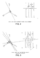
- FIG. 2 there is shown a contrasting depiction of an aircraft in an isometric display on the left, and in a parallel 4-coordinate .plane on the right.
- isometric display both the relative position of the aircraft and an indication of the path followed are set out.
- the parallel coordinate plane on the right is formed such that the axes are placed parallel and equidistant from each other. Since the aircraft position and motion are described in three spatial dimensions and one temporal dimension, then each such "point" in 4-space may be plotted uniquely in this parallel plane.
- One comparison between the left and right depictions is that the trajectory (the relation between space variables and time) can be represented and displayed on the parallel plane explicitly, whereas only the path can be indicated on the other.
- the line t given by (1) is represented in parallel coordinates by the points
- an aircraft's trajectory is a function of three space variables (x1, x2, x3) and one temporal variable (t).
- Such a trajectory can be represented with three planar points T:1, 1:2, and 2:3.
- the position of the aircraft may be found on the parallel coordinate planar display as follows:
- each point in N-space can be represented by a polygonal line and a counterpart set of line segments and their linear equations as in (3).
- the horizontal position of the points representing the trajectory is determined only from the quantities m(i). These can be interpreted as the slope of the line's projection on the 2-dimensional plane x(i), x(i+1), so that if x3 is the altitude of the aircraft, the ground position is described by x1, x2.
- An angular deviation from the true ground heading shows up as a lateral deviation of the point 1:2.
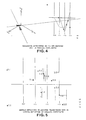
- Figures 6 and 7 there are contrasted the closest approach of two aircraft isometrically and in parallel coordinate planar view.
- the difference of Figure 7 over Figure 6 lies in that each aircraft is encased within a cylindrical envelope.
- the distance between the aircraft can be computed according to the relationship (14) with their positions otherwise determined.
- the closest approach to other trajectories can be ascertained to verify minimum acceptable separation. If the separation is not acceptable, then a prompt is activated to alert the operator and other trajectories with appropriate separation recommended.
- FIG 8 there is shown the parallel coordinate planar display of two aircraft flying on the same path but separated in time. This would be the case when flying between two omni stations.
- points 1:2 and 2:3 are shared since they describe the path.
- the aircraft are flying with the same velocity since both points marked T:1 have the same horizontal coordinate. If, on the other hand, one point was between the T and x1 axes and the other point was outside, then they would be flying in opposite directions.
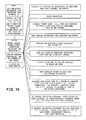
- Figure 15 when taken together with the table, there is shown respectively the flow of control and implementing APL sequences in detecting and displaying aircraft trajectories, and ascertaining collision opportunities and avoidances.
- Figure 15 sets out eleven activities performed by the processor and interactive display responsive to coded signals provided by the detection and ranging system.
- the coded signals define one or more aircraft trajectories.
- the activities set out in Figure 15 ascertain the state of the airspace in terms of (1) trajectories encased within a defined volume, and (2) prospective collisions. These are electronically mapped and displayed on the parallel N-coordinate plane as illustratively set out in Figures 4-11. These activities are conducted reiteratively so that in the event of either a pending collision or if the flight margins are too close, then one or more trajectories can be adjusted in space and time and redisplayed. Allocations and adjustments of space paths can then be communicated to affected aircraft.
- the table sets out APL instruction sequences by which an APL processor and interactive display interface execute the steps of the method of this invention.
- This embodiment contemplates an interpretive processor.
- compiler-based language equivalents drawn in PASCAL, FORTRAN, and the like are believed to be well within the scope of the skilled artisan in view of this disclosure.
- the APL embodiment operates through an arrangement of independently executable and callable modules / processes termed "defined functions".
- the coded signals are placed into labeled vector buffers (LNS,AVAILNS).
- this embodiment permits an operator, acting through one of the defined functions (AT) having a menued display interface, to select one of several processing options (AT ⁇ OPTION1.3,4,6,16-20).
- AT ⁇ OPTION1.3,4,6,16-20 processes the coded signals and causes counterpart trajectories encased within defined volumes to be displayed on the parallel coordinate plane in the manner of Figure 7. Warning indications are automatically flashed if predesignated margins are exceeded.
- Another option, AT ⁇ OPTION16 causes angular deviations from assigned trajectories to be displayed in the manner of Figure 5.
- AT ⁇ OPTION3 causes a display of the closest points between two trajectories to be made in the manner of Figure 6.
- function AT ⁇ OPTION19 causes any collision with an input trajectory to be displayed in the manner of Figures 10 and 11.
- option AT ⁇ OPTION20 ascertains and displays a path parallel to a given trajectory.
- Other performance attributes expressed in the APL sequences should be readily apparent from inspection thereof in the table.
Abstract
Critical differences in the position and motion of aircraft in congested N-dimensional airspace are highly discernible when processed and mapped onto a parallel N-coordinate plane. Trajectory intersection in both time and space may be constantly monitored. The airspace may be accurately controlled by descriptively and prescriptively configuring proposed trajectories and monitoring critical differences before assignment to aircraft. Attributes such as angular deviation, in addition to closing speed and distance, can be evaluated.
Description
- This invention relates to air traffic control and, more particularly, to the automatic processing and presentation of aircraft trajectory data to facilitate collision avoidance and routing.
- In the prior art, it is known that the position and motion of aircraft in an airspace can be periodically detected and measured by an active or passive detection and ranging system. The ranging system sends the periodically obtained information in the form of coded signals to a processor and an associated interactive interface. In turn, the processor causes the signals to be transformed and displayed at the interface. The interface may include a surface such as a polychromatic cathode ray tube upon which the aircraft position information is shown. means coupling the processor for varying the display, means for controlling the detection and ranging system, and means for communicating with aircraft. Such a system, although frequently sited on.the ground, may likewise be air or seaborne.
- Typifying the prior art patent literature are:
- (1) Buchanan et al, U. S. Patent 4,196,474, "Information Display Method and Apparatus for Air Traffic Control", issued April 1, 1980.
- (2) Corcoran, U. S. Patent 4,023,158, "Real Three-dimension Visual Display Arrangement", issued May 10, 1977.
- (3) Hammack, U. S. Patent 3,996,590, "Method and Apparatus for Automatically Detecting and Tracking Moving Objects and Similar Applications", issued December 7, 1976.
- (4) Levine, U. S. Patent 3,971,025, "Airport Ground Surveillance System with Aircraft Taxi Control Feature", issued July 20, 1976.
- (5) Gilbert et al, U. S. Patent 3,925,750, "Air Traffic Control System", issued December 9, 1975.
- These references describe systems and methods for providing the near real-time isometric display of state variable data (aircraft identity, position, velocity) in two and three dimensions. However, significant dimensional information may be lost. For instance, a 2-dimensional radar display may show position (range) but no height data. Alternatively, position information may be shown in polar coordinates dimensionally graphed, but other information such as height and ground speed may appear only as numerical tags to the display blip.
- Notwithstanding, recent years have witnessed a crowding of the skies around air traffic control (ATC) sites with increasing numbers of both scheduled and nonscheduled aircraft seeking entrance or exit from or to designated airspace and ground facilities. One consequence is the crowding of information appearing at the counterpart ATC displays. This means that ATC personnel and others utilizing the displays may overlook data present, not notice data absent, and otherwise misinterpret the system state. This becomes critical where the displayed data concerns potential collisions involving closing distances and velocities among aircraft. Parenthetically, Gilbert. in Figure 6, exhibits a typical crowded airborne ATC display.
- Another source of prior art relates to a theory of optimal control systems using N-dimensional geometry.
This is taught by: - (6) Inselberg et al, "Intelligent Instrumentation and Process Control", Proceedings of the Second Conference on AI Applications, IEEE, December 11-13, 1985, pp. 302-307, and references cited therein.
- According to lnselberg, an N-dimensionalicoordinate geometry may be used to characterize N men- surable attributes of each object in a system. Relatedly, process control consists of maintaining some relations defined on those attributes invariant and others constrained. Optimal process control is one in which:
- (a) interior points (points in N-space) to a hypersurface represent the acceptable states of a system model,
- (b) control requires staying within the interior of said surface, and
- (c) a current abbreviated description of the system state, i.e., display, involves the mapping of points in N-space into convenient 2-dimensional form.
- Inselberg proposes that the N-dimensional to 2-dimensional mapping for a display be in the form of N axes parallel, say, to the y-axis in the xy-plane. Each point in the higher dimension can have its N coordinates (cl,c2,c3,...,cN) depicted as a polygonal line in the xy-plane. At page 305, he points out that a general convex hypersurface in N-dimensions can be represented by the "envelope" of the set of polygonal lines. This is analogous in the 2-or 3-dimensional space of defining a curve as the "envelope" of its tangents, and defining a surface as the "envelope" of its tangent planes. Reference also can be made to Edna E. Kramer, "The Nature and Growth of Modern Mathematics". Princeton University Press, copyright 1981, page 160; and Aleksandrov et al, "Mathematics, Its Content, Method, and Meaning", MIT Press, copyright 1963.
Vol 2. pp. 108-110. - The Inselberg article further points out several properties of this hypersurface envelope as mapped onto the xy-plane. First. a "feasible point" satisfying control requirements is interior to the hypersurface. Second, the relation between adjacent ones of the N-parallel axes is defined by the envelope shape. Third, the envelope shape is dependent upon the order in which the axes appear. Lastly, varying the order permits a way of finding and displaying these "feasible points".
- The present invention is disclosed in the attached claims, and it is an object of this invention to devise a method for the processing and displaying of system state data, especially variable data. in an air traffic control (ATC) system context. It is a related object to devise a method for ATC collision avoidance and routing in which the processed and displayed data explicitly show aircraft trajectories in the form of time and space variables. It is still another object to devise a collision avoidance method and maintenance of acceptable spatial separation between aircraft at the time trajectories are assigned to corresponding aircraft. It is yet another object that such method avoid dimensional information loss, such as is occasioned by recourse to present-day methods.
- This invention is premised upon the unexpected observation that trajectories of aircraft measured frequently enough as points in a space of four or more dimensions can be mapped into an electronically displayable plane of four or more parallel coordinate axes in the form of three labeled points. It is also appreciated that a point of collision between two aircraft trajectories in this higher dimension space can be processed as a "point in time" of intersection of a pair of lines and manifest likewise as a polygonal line on the electronically displayable plane. Likewise, a zone of either collision danger or avoidance modeled as a "sphere" about a point of intersection or as a cylindrical or other shaped volume about each actual or proposed trajectory in the higher dimensional space can be mapped onto the display. Similarly, any angular deviations from an assigned trajectory are mappable as a lateral deviation on the display.
- The invention is embodied as a method for detecting and displaying position and motion information among objects distributed in a volume, said information being periodically supplied by a suitable active or passive detection and ranging system in the form of coded signals to a processor and an associated interactive interface.
- In this invention, an aircraft trajectory is considered to be a relation between three space variables and time. While the trajectory may be curved in fact, if it is sampled frequently enough, the trajectory may be approximated and processed as if it were linear. The sampling consists of the coded signal returns provided by the detection and ranging system on a periodic basis to the processor and interactive display. Curved trajectories can be directly processed at increased cost.
- The methods steps comprise (a) generating and displaying at the interface visible indicia of an N-axis parallel coordinate plane, N being a positive integer; (b) populating the displayed plane with display representations of polygonal lines, each line representing a unique N-tuple, said N-tuple being either a multivariate data point obtained from the received encoded signals or a point derived from said signals and satisfying a predetermined relation; (c) filtering the displayed populated plane to discriminate the attributes, such as closing distance and velocity, as a function of their N-dimensional structure; and (d) base collision avoidance and routing algorithms on the geometrical representation.
- Figure 1 depicts an aircraft detection and ranging system coupling a processor and interactive display means according to the prior art.
- Figures 2-3 contrast single and multiple aircraft paths in three coordinate planes fashionable in the prior art with trajectories mapped onto parallel 4-axis coordinate display planes according to the method of the invention.
- Figure 4 illustrates the ambiguity of aircraft on an apparent collision course observed on prior art ATC display means and the express resolution on the parallel 4-axis coordinate display plane of the invention.
- Figure 5 sets out the manner by which angular deviation from assigned trajectories is displayed as lateral deviation per the invention.
- Figures 6-11 depict the representation of aircraft on a collision course in both prior art and parallel 4- axis coordinate plane displays emphasizing the manner by which critical time and space intersection information is delineated according to the invention.
- Figures 12-14 briefly show conceptual "mapping" of the geometric representation residues, in parallel coordinates, possible conflicts, and how it may be used for collision avoidance and trajectory assignment.
- Figure 15 shows the flow of control in detecting and displaying aircraft trajectories, and ascertaining collision opportunities and avoidances.
- Table 1 sets out APL source code sequences following the general control flow of Figure 15 for implementing the method of the invention when executed on a suitable APL processor portion of an ATC system.
- Referring now to Figure 1. there is shown an active detection and ranging system used in the prior art to illuminate targets with electromagnetic waves and ascertain target identity, position, and motion. These target attributes are obtained from modulations encrusted on the echos by interaction between the waves and the target. In the 4-dimensional radar tracker portion, position and movement data such as
range 1, azimuth andelevation angles 5, 7, andDoppler data 3 are supplied to a processor interactive interface (not shown). A portion of the conventional processing of position information responsive to azimuth and elevation angle data is set out in the lower portion of Figure 1. - Passive systems, such as identify friend or foe (IFF) transponders embedded in targets, may also provide some of the same information. Processors converting the data also drive the displays. Additional description of radar systems may be found in Barton, "Radar Systems Analysis", Prentice-Hall, Inc., copyright 1964, pp. 381-393 and 428-435. Also, Levine (reference 4) shows a geometric arrangement of "blinking" radars in combination with a processor and 2-dimensional target display to regulate aircraft ground (taxi) movement. Since the invention concerns processing and display of target data already acquired, no additional description of detection and ranging systems is believed necessary in order to otherwise appreciate the advance set out in this specification.
- Referring now to Figure 2, there is shown a contrasting depiction of an aircraft in an isometric display on the left, and in a parallel 4-coordinate .plane on the right. In the isometric display, both the relative position of the aircraft and an indication of the path followed are set out.
- In Figure 2, the parallel coordinate plane on the right is formed such that the axes are placed parallel and equidistant from each other. Since the aircraft position and motion are described in three spatial dimensions and one temporal dimension, then each such "point" in 4-space may be plotted uniquely in this parallel plane. One comparison between the left and right depictions is that the trajectory (the relation between space variables and time) can be represented and displayed on the parallel plane explicitly, whereas only the path can be indicated on the other.
- In Figure 3, the paths and counterpart trajectories of several aircraft are shown in a manner similar to that shown in Figure 2. The contrasting depictions are likewise set out in Figures 4 and 6-11. In order to more fully appreciate the significance of the parallel N-coordinate representation of aircraft position and movement information over that in the prior art requires a brief excursion.
- The key to understanding the parallel plane representation is to be found in Figures 12-14. First, a Cartesian or xy-plane is defined in Figure 12. Second, starting with the y-axis and in the direction along the x-axis, N copies of the real number line are spaced equidistant and perpendicular. These are the axes of the parallel coordinate system for N-space. The axes all have the same positive orientation as the y-axis. The description of a geometrical system having N variables in N-space is denoted in the literature as RN.
- In Figure 12, a point c having N-coordinates (c1,c2,...,cN) is represented as a polygonal line whose N vertices are at (i-1.ci) on the x-axis for all i = 1,2,...,N. In this way, a one-to-one correspondence between points in RN and planar polygonal lines with vertices in x1,x1,...,xN is established. For each segment joining vertices on adjacent axes, the whole line containing it is taken as part of the polygonal line representing the point. This polygonal line is made up of N-1 lines, each of which can be described by an independent linear equation. This set of equations can be satisfied by the coordinates of its points. The equations can be expressed either in terms of adjacent variables or in terms of a single variable.
- In terms of adjacent variables:


- The line t given by (1) is represented in parallel coordinates by the points


- If two points determine a line, even in N-space, then how would a pair of lines (trajectories) intersecting in N-space appear on the parallel N-coordinate plane? The answer by analogy in 2-space or in 3-space is that a pair of straight lines intersect at a point. Thus, the intersection point in N-space would be represented in a parallel N-coordinate plane as a polygonal line. In this regard. Figure 13 shows the polygonal line representation of the point of intersection of two lines in 5-space using the above-mentioned base vanable, while Figure 14 relies upon the adjacent variable form.
- Consider two lines l, t' given by


- This leads to an intuitive construction. On the xy-plane, form the "construction" lines
P ' joiningℓ 1 ; toℓ '1i . Then,
- The P "s must intersect on the x.-axis since x, is the base variable used in the description (5). In fact, P' = (a, pi), where xi(P) = pi. The equivalent construction, based on the adjacent variable representation of the lines, is shown in Figure 14. Specifically, tnt' = P ↔ ∇i = 1,...,N - 1

p i,i-1 joins the pointℓ i,i+1 toℓ i , i + i , and pi,i+1 = (pi,pi+1). The generalization to other line representations is direct. Clearly, these constructions can be used to verify nonintersection. - It appears desirable to not only ascertain collision points, but to ascertain a zone of either collision danger or avoidance between aircraft. This, in part, motivates the consideration of the proximity between a pair of
lines 1 and 1' (trajectories) in N-space or RN. Thelines 1 and 1' are defined by
- By this is meant finding the closest points, P ∈ℓ, P' ∈ ℓ', and the distance between them. Rather than using a more standard approach, consider "fitting" a sphere with center P ∈ and tangent to a point P' ∈ t'. The radius r of this sphere is the distance between the two lines, and P and P' are the points in question. To accomplish this "fit", for any number a let P E ℓ with x,(P) = a and S the sphere with radius r and centered at P, i.e.,


- Expanding and rearranging the above yields a'2M' + 2a'(D' -aC) - 2aD + a2M + B = r2 (9)


- The gist in (9) is the quadratic relationship between the three unknowns a, a' and r. Completing the squares in a' and a and letting Q = MM' -C2 results in

- Since Q and M' are nonnegative


- By the way, in R2 with m2#m2 (12) yields the identity r = 0 since the lines intersect. The points P and P' determine the line n which is normal to both t and t'
- In applying the above to collision avoidance in ATC, it is useful to let x, in (8) be the time variable relabeled t. The factors of interest then are the closest points in time. They are given in terms of the time, say x. = a, which minimizes r and are found by a similar argument to be

- These results can be amended to obtain a line representation in terms of the coordinates of two of its points, and to obtain the proximity results above for intervals rather than for whole lines.
- Referring again to Figures 2-11, several general advantages of the parallel 4-coordinate planar form of an ATC display should be stated explicitly. These include (a) unambiguous indication of the past, present, or future position of an aircraft trajectory; (b) assignment of trajectories for specified time intervals; (c) indication of flight deviation from the trajectory by transforming angular deviations into easily detectable lateral deviations of 1 or 2 points representing the aircraft's path; (d) detection and display of the time at which any pair of aircraft are closest, along with the position and distance at the closest approach; and (e) exhibiting properties of special trajectories as found. for example, where several aircraft occupy the same space path at different times with varying velocities.
- Referring again to Figure 2. it is apparent that an aircraft's trajectory is a function of three space variables (x1, x2, x3) and one temporal variable (t). Such a trajectory can be represented with three planar points T:1, 1:2, and 2:3. At any given time t, the position of the aircraft may be found on the parallel coordinate planar display as follows:
- (a) find the line through the value t on the T axis and the point T:1.
- (b) the intersection of the line in step (a) with the x1 axis yields the value for x1 = a1,
- (c) find the line through the value x1 = a1 and the point 1:2,
- (d) the intersection of the line in step (c) with the x2 axis yields the value for x2 = a2, and
- (e) repeat steps (c) and (d) with respect to finding a linear intersection with the x3 axis to find x3 = a3.
- The joining of this polygonal line associates the space and time values. The corresponding situation for several aircraft is represented on the parallel coordinate plane in Figure 3.
- As mentioned, conventional isometric displays exhibit distortion. This is indicated in Figure 4 on the lefthand side where the aircraft appear collision bound. However, their spatial separation is clear on the parallel coordinate planar diagram to the right.
- Referring now to Figure 5, there is shown an aircraft's angular deviation from an assigned trajectory as it appears on the electronic parallel N-coordinate planar display. It should be recalled that each point in N-space can be represented by a polygonal line and a counterpart set of line segments and their linear equations as in (3). The horizontal position of the points representing the trajectory is determined only from the quantities m(i). These can be interpreted as the slope of the line's projection on the 2-dimensional plane x(i), x(i+1), so that if x3 is the altitude of the aircraft, the ground position is described by x1, x2. An angular deviation from the true ground heading shows up as a lateral deviation of the point 1:2. In Figure 5, an angular deviation of ±5 degrees from the assigned ground heading is shown as a horizontal range centered on the point 1:2 of each trajectory. The difference in interval lengths is due to the nonlinear scale of the angle. In this regard, the scale is linear only as the tangent m(i) of the angle.
- Referring now to Figures 6 and 7, there are contrasted the closest approach of two aircraft isometrically and in parallel coordinate planar view. The difference of Figure 7 over Figure 6 lies in that each aircraft is encased within a cylindrical envelope. The distance between the aircraft can be computed according to the relationship (14) with their positions otherwise determined. Note, prior to assigning any given trajectory, the closest approach to other trajectories can be ascertained to verify minimum acceptable separation. If the separation is not acceptable, then a prompt is activated to alert the operator and other trajectories with appropriate separation recommended.
- Referring now to Figure 8, there is shown the parallel coordinate planar display of two aircraft flying on the same path but separated in time. This would be the case when flying between two omni stations. In Figure 8, points 1:2 and 2:3 are shared since they describe the path. It is also known from the figure that the aircraft are flying with the same velocity since both points marked T:1 have the same horizontal coordinate. If, on the other hand, one point was between the T and x1 axes and the other point was outside, then they would be flying in opposite directions.
- Referring now to Figures 9-11, there is shown contrast display of isometric and parallel coordinate plane displays of aircraft flying different straight-line segments. It is the case that an aircraft is assigned a trajectory for only a finite time interval. The isometric representations can only show if their paths intersect. This is acceptable as long as the aircraft do not pass through the same point in space at the same time. From parallel coordinates this, of course, can immediately be found. For space and time intersection, the points T:1, 1:2, and 2:3 must satisfy the intersection construction as set out above; while for path intersection, only the points 1:2 and 2:3 must satisfy the construction. This is clearly shown in Figures 10 and 11. In this invention, collision avoidance is based on this observation.
- Referring now to Figure 15, when taken together with the table, there is shown respectively the flow of control and implementing APL sequences in detecting and displaying aircraft trajectories, and ascertaining collision opportunities and avoidances. Figure 15 sets out eleven activities performed by the processor and interactive display responsive to coded signals provided by the detection and ranging system. The coded signals define one or more aircraft trajectories.
- The activities set out in Figure 15 ascertain the state of the airspace in terms of (1) trajectories encased within a defined volume, and (2) prospective collisions. These are electronically mapped and displayed on the parallel N-coordinate plane as illustratively set out in Figures 4-11. These activities are conducted reiteratively so that in the event of either a pending collision or if the flight margins are too close, then one or more trajectories can be adjusted in space and time and redisplayed. Allocations and adjustments of space paths can then be communicated to affected aircraft.
- The table sets out APL instruction sequences by which an APL processor and interactive display interface execute the steps of the method of this invention. This embodiment contemplates an interpretive processor. However, compiler-based language equivalents drawn in PASCAL, FORTRAN, and the like are believed to be well within the scope of the skilled artisan in view of this disclosure.
- The APL language and machine performance characteristics are well appreciated. Reference should be made to Gilman et al, "APL: An Interactive Approach". 2nd Edition. John Wiley & Sons. Inc., copyright 1976. An excellent guide for appreciating the instruction sequence embodiment of APL2 is set out in the International Business Machines Corporation APL2 Language Manual. publication S821-3015.
- The APL embodiment operates through an arrangement of independently executable and callable modules/processes termed "defined functions". In this embodiment. the coded signals are placed into labeled vector buffers (LNS,AVAILNS). Also, this embodiment permits an operator, acting through one of the defined functions (AT) having a menued display interface, to select one of several processing options (ATΔOPTION1.3,4,6,16-20). For instance, one of the options, ATΔOPTION1, processes the coded signals and causes counterpart trajectories encased within defined volumes to be displayed on the parallel coordinate plane in the manner of Figure 7. Warning indications are automatically flashed if predesignated margins are exceeded. Another option, ATΔOPTION16, causes angular deviations from assigned trajectories to be displayed in the manner of Figure 5. Yet another option, ATΔOPTION3, causes a display of the closest points between two trajectories to be made in the manner of Figure 6. Of interest is defined function ATΔOPTION19. This option causes any collision with an input trajectory to be displayed in the manner of Figures 10 and 11. In contrast, option ATΔOPTION20 ascertains and displays a path parallel to a given trajectory. Other performance attributes expressed in the APL sequences should be readily apparent from inspection thereof in the table.


- Various additional modifications and adaptations of the present invention will suggest themselves to those skilled in this art. The foregoing description is considered illustrative.
Claims (12)
1. A method for detecting and displaying position and motion information among objects distributed in an N-dimensional space, said information being periodically supplied by a suitable active or passive detection and ranging system in the form of signals encoding multivariate data points, said encoded signals sent to a processor and an associated interactive display interface, comprising the processor-controlled steps of:
generating and displaying at the interface in the logical domain an N axes parallel coordinate plane, N being a positive integer;
populating the displayed plane with representations of polygonal lines, each line representing a unique N-tuple, said N-tuple being either a multivariate data point obtained from the received encoded signals or a point derived from said signals and satisfying a predetermined relation; and
filtering the displayed populated plane to discriminate selected attributes such as closing distance and velocity as a function of their N-dimensional structure.
2. A method according to claim 1, wherein the displayed plane includes a velocity axis and, orthogonal thereto, four parallel coordinate axes formed from three axes of spatial dimension and one temporal axis (Figure 2).
3. A method according to claim 2, wherein the polygonal line representations in the displayed plane of counterpart position or motion of objects nonintersecting in N-dimensional space and time being manifest on said displayed plane by a discernible separation between said polygonal lines in at least one parallel coordinate (Figures 3, 4, 6, 7).
4. A method according to claim 2, wherein angular deviations of an object moving through a trajectory being manifest on the displayed plane by lateral deviations about predetermined planar points (Figure 5).
5. A method according to claim 4, wherein each angular deviation being extracted, processed, and displayed as the slope m(i) of the polygonal line's projection onto a 2-dimensional space x(i), x(i + 1
6. A method according to claim 2, wherein a linear approximation to a designated segment of a trajectory for each object being defined by at least two N-tuples and being manifest on the displayed plane as an area bounded by polygonal lines (Figures 9, 10).
7. A method according to claim 6, wherein objects having intersecting trajectories being manifest on the displayed plane in the forming of polygonal line bounded areas having no discernible separation between said bounded areas on any of the parallel coordinate axes (Figures 10, 11).
8. A method according to claim 1, wherein said displayed coordinate plane includes a velocity axis and, orthogonal thereto, four parallel coordinate axes formed from three axes of spatial dimension and one temporal axis (Figure 2); and wherein the displayed populated plane is filtered by processing the polygonal line representations in the displayed plane of counterpart position or motion of objects nonintersecting in N-dimensional space and time, said nonintersection being manifest on said displayed plane by a discernible separation between said polygonal lines in at least one parallel coordinate (Figures 3, 4, 6, 7).
9. A method according to claim 1, wherein said displayed coordinate plane includes a velocity axis and, orthogonal thereto, four parallel coordinate axes formed from three axes of spatial dimension and one temporal axis (Figure 2); and wherein the displayed populated plane is filtered by processing the polygonal line representations such that angular deviations of an object moving through a trajectory being manifest on the displayed plane by lateral deviations about predetermined planar points (Figure 5).
10. A method according to claim 9, wherein each angular deviation being extracted, processed, and displayed as the slope m(i) of the polygonal lines's projection onto a 2-dimensional space x(i), x(i + 1
11. A method according to claim 1, wherein said displayed coordinate plane includes a velocity axis and, orthogonal thereto, four parallel coodinate axes formed from three axes of spatial dimension and one temporal axis (Figure 2); wherein the populating step further comprises a linear approximation to a designated segment of a trajectory for each object being defined by at least two N-tuples and being manifest on the displayed plane as an area bounded by polygonal lines (Figures 9, 10); and wherein the displayed populated plane is filtered by processing the polygonal line representations in the displayed plane such that objects having intersecting trajectories being manifest on the displayed plane in the forming of polygonal line bounded areas on any of the parallel coordinate axes (Figure 10,11).
12. The method according to claim 11, wherein said method further includes the steps of causing visible indication on said interface to be made of trajectories whose discernible separation as mapped onto at least one parallel coordinate in the planar display is less than a predetermined amount.
Applications Claiming Priority (2)
| Application Number | Priority Date | Filing Date | Title |
|---|---|---|---|
| US22832 | 1987-03-06 | ||
| US07/022,832 US4823272A (en) | 1987-03-06 | 1987-03-06 | N-Dimensional information display method for air traffic control |
Publications (2)
| Publication Number | Publication Date |
|---|---|
| EP0283723A2 true EP0283723A2 (en) | 1988-09-28 |
| EP0283723A3 EP0283723A3 (en) | 1989-04-05 |
Family
ID=21811665
Family Applications (1)
| Application Number | Title | Priority Date | Filing Date |
|---|---|---|---|
| EP88102430A Withdrawn EP0283723A3 (en) | 1987-03-06 | 1988-02-19 | An n-dimensional information display method for air traffic control |
Country Status (3)
| Country | Link |
|---|---|
| US (1) | US4823272A (en) |
| EP (1) | EP0283723A3 (en) |
| JP (1) | JPS63225122A (en) |
Cited By (5)
| Publication number | Priority date | Publication date | Assignee | Title |
|---|---|---|---|---|
| EP0380460A2 (en) * | 1989-01-23 | 1990-08-01 | International Business Machines Corporation | Conflict detection and resolution between moving objects |
| EP0415587A2 (en) * | 1989-08-29 | 1991-03-06 | Hughes Aircraft Company | Early warning tracking system |
| WO2003091967A1 (en) * | 2002-04-23 | 2003-11-06 | Raytheon Company | Multiple approach time domain spacing aid display method and system |
| CN105890599A (en) * | 2016-04-12 | 2016-08-24 | 上海牵挂网络科技有限公司 | Filter algorithm based on geographical location footprint noisy points |
| CN107786257A (en) * | 2017-10-19 | 2018-03-09 | 清华大学 | A kind of Constellation optimization method and apparatus for airborne vehicle monitoring |
Families Citing this family (33)
| Publication number | Priority date | Publication date | Assignee | Title |
|---|---|---|---|---|
| US5208591A (en) * | 1989-09-29 | 1993-05-04 | Honeywell Inc. | Track extension for use with ATCRBS surveillance procedures |
| US5157615A (en) * | 1990-01-09 | 1992-10-20 | Ryan International Corporation | Aircraft traffic alert and collision avoidance device |
| US6006158A (en) * | 1993-09-07 | 1999-12-21 | H. R. Pilley | Airport guidance and safety system incorporating lighting control using GNSS compatible methods |
| US5867804A (en) * | 1993-09-07 | 1999-02-02 | Harold R. Pilley | Method and system for the control and management of a three dimensional space envelope |
| AU8877991A (en) * | 1990-10-09 | 1992-04-28 | Harold R. Pilley | Airport control/management system |
| US5173861A (en) * | 1990-12-18 | 1992-12-22 | International Business Machines Corporation | Motion constraints using particles |
| DE4243669A1 (en) * | 1992-12-23 | 1994-06-30 | Deutsche Aerospace | Process for monitoring an area and arrangement for carrying out the process |
| US5406289A (en) * | 1993-05-18 | 1995-04-11 | International Business Machines Corporation | Method and system for tracking multiple regional objects |
| US5337057A (en) * | 1993-07-12 | 1994-08-09 | Alliedsignal Inc. | Non-linear radar range scale display arrangement |
| US5519618A (en) * | 1993-08-02 | 1996-05-21 | Massachusetts Institute Of Technology | Airport surface safety logic |
| US5374932A (en) * | 1993-08-02 | 1994-12-20 | Massachusetts Institute Of Technology | Airport surface surveillance system |
| US5675720A (en) * | 1993-09-14 | 1997-10-07 | Fujitsu Limited | Method of searching for points of closest approach, and preprocessing method therefor |
| US5420968A (en) * | 1993-09-30 | 1995-05-30 | International Business Machines Corporation | Data processing system and method for displaying dynamic images having visual appearances indicative of real world status |
| US5570099A (en) * | 1993-10-15 | 1996-10-29 | Loral Federal Systems Company | TDOA/FDOA technique for locating a transmitter |
| US5537119A (en) * | 1993-12-21 | 1996-07-16 | Colorado State University Research Foundation | Method and system for tracking multiple regional objects by multi-dimensional relaxation |
| US5959574A (en) * | 1993-12-21 | 1999-09-28 | Colorado State University Research Foundation | Method and system for tracking multiple regional objects by multi-dimensional relaxation |
| US5636123A (en) * | 1994-07-15 | 1997-06-03 | Rich; Richard S. | Traffic alert and collision avoidance coding system |
| US5546516A (en) * | 1994-12-14 | 1996-08-13 | International Business Machines Corporation | System and method for visually querying a data set exhibited in a parallel coordinate system |
| US5835059A (en) * | 1995-09-01 | 1998-11-10 | Lockheed Martin Corporation | Data link and method |
| JP2907105B2 (en) * | 1996-03-27 | 1999-06-21 | 日本電気株式会社 | 3D display device |
| JP3406478B2 (en) * | 1997-06-06 | 2003-05-12 | 沖電気工業株式会社 | Aircraft position display device for terminal control console |
| US6049341A (en) * | 1997-10-20 | 2000-04-11 | Microsoft Corporation | Edge cycle collision detection in graphics environment |
| IL125289A (en) | 1998-07-09 | 2004-03-28 | Ehud Ezroni | Aircraft communication system |
| US6750864B1 (en) | 1999-11-15 | 2004-06-15 | Polyvista, Inc. | Programs and methods for the display, analysis and manipulation of multi-dimensional data implemented on a computer |
| US6604044B1 (en) | 2002-02-14 | 2003-08-05 | The Mitre Corporation | Method for generating conflict resolutions for air traffic control of free flight operations |
| DE102005020352A1 (en) * | 2005-05-02 | 2007-08-16 | Fraunhofer-Gesellschaft zur Förderung der angewandten Forschung e.V. | Chemical product`s production process controlling method for e.g. pipe system, involves providing variables by individual adjustment in production process and measuring variables in process, to generate horizon, with three scale arms |
| US8346682B2 (en) * | 2009-01-23 | 2013-01-01 | The United States Of America, As Represented By The Secretary Of The Navy | Information assisted visual interface, system, and method for identifying and quantifying multivariate associations |
| FR2965087B1 (en) * | 2010-09-21 | 2013-05-17 | Dassault Aviat | APPARATUS FOR ASSISTING THE CREW OF AN AIRCRAFT DURING FLIGHT LEVEL CHANGES THEREOF |
| US9939522B2 (en) * | 2013-10-13 | 2018-04-10 | Oculii Corp | Systems and methods for 4-dimensional radar tracking |
| JP6532762B2 (en) * | 2015-06-02 | 2019-06-19 | 株式会社東芝 | INFORMATION GENERATION SYSTEM, APPARATUS, METHOD, AND PROGRAM |
| FR3081230B1 (en) * | 2018-05-17 | 2020-07-03 | Thales | METHOD FOR MEASURING IN OPERATING OPERATION CERTAIN CHARACTERISTICS OF THE ON-BOARD TRANSPONDER USING SECONDARY RADAR |
| US11556816B2 (en) * | 2020-03-27 | 2023-01-17 | International Business Machines Corporation | Conditional parallel coordinates in automated artificial intelligence with constraints |
| CN114202621B (en) * | 2022-02-17 | 2022-06-24 | 北京开运联合信息技术集团股份有限公司 | Method and device for realizing mass space target display based on B/S architecture |
Citations (2)
| Publication number | Priority date | Publication date | Assignee | Title |
|---|---|---|---|---|
| US3898659A (en) * | 1969-06-09 | 1975-08-05 | Us Navy | Data storage and conversion system |
| DE3210694A1 (en) * | 1982-03-24 | 1983-10-06 | Siemens Ag | Flight surveillance device |
Family Cites Families (8)
| Publication number | Priority date | Publication date | Assignee | Title |
|---|---|---|---|---|
| US3996590A (en) * | 1961-02-02 | 1976-12-07 | Hammack Calvin M | Method and apparatus for automatically detecting and tracking moving objects and similar applications |
| US3534367A (en) * | 1968-01-30 | 1970-10-13 | Nasa | Traffic control system and method |
| US3623090A (en) * | 1968-11-15 | 1971-11-23 | Butler National Corp | Air traffic control system |
| US3775767A (en) * | 1972-01-17 | 1973-11-27 | Gen Res Corp | Air-traffic regulating systems |
| US3971025A (en) * | 1973-01-02 | 1976-07-20 | International Telephone And Telegraph Corporation | Airport ground surveiliance system with aircraft taxi control feature |
| US4023158A (en) * | 1973-10-15 | 1977-05-10 | International Telephone And Telegraph Corporation | Real three-dimension visual display arrangement |
| US4196474A (en) * | 1974-02-11 | 1980-04-01 | The Johns Hopkins University | Information display method and apparatus for air traffic control |
| US4706198A (en) * | 1985-03-04 | 1987-11-10 | Thurman Daniel M | Computerized airspace control system |
-
1987
- 1987-03-06 US US07/022,832 patent/US4823272A/en not_active Expired - Lifetime
-
1988
- 1988-02-05 JP JP63024104A patent/JPS63225122A/en active Pending
- 1988-02-19 EP EP88102430A patent/EP0283723A3/en not_active Withdrawn
Patent Citations (2)
| Publication number | Priority date | Publication date | Assignee | Title |
|---|---|---|---|---|
| US3898659A (en) * | 1969-06-09 | 1975-08-05 | Us Navy | Data storage and conversion system |
| DE3210694A1 (en) * | 1982-03-24 | 1983-10-06 | Siemens Ag | Flight surveillance device |
Non-Patent Citations (2)
| Title |
|---|
| NAVY TECHNICAL DISCLOSURE BULLETIN, vol. 2, no. 4, April 1977, pages 56-60, Arlington, VA, US; D.D. HOWARD et al.: "Four-dimensional isometric radar target image display by digital techniques" * |
| PROCEEDINGS OF THE SECOND CONFERENCE ON ARTIFICIAL INTELLIGENCE APPLICATIONS, Miami Beach, Florida, 11th-13th December 1985, pages 302-307, IEEE, New York, US; A. INSELBERG et al.: "Intelligent instrumentation & process control" * |
Cited By (10)
| Publication number | Priority date | Publication date | Assignee | Title |
|---|---|---|---|---|
| EP0380460A2 (en) * | 1989-01-23 | 1990-08-01 | International Business Machines Corporation | Conflict detection and resolution between moving objects |
| EP0380460A3 (en) * | 1989-01-23 | 1991-06-12 | International Business Machines Corporation | Conflict detection and resolution between moving objects |
| EP0415587A2 (en) * | 1989-08-29 | 1991-03-06 | Hughes Aircraft Company | Early warning tracking system |
| AU612082B1 (en) * | 1989-08-29 | 1991-06-27 | Raytheon Company | Early warning tracking system |
| EP0415587A3 (en) * | 1989-08-29 | 1992-12-23 | Hughes Aircraft Company | Early warning tracking system |
| WO2003091967A1 (en) * | 2002-04-23 | 2003-11-06 | Raytheon Company | Multiple approach time domain spacing aid display method and system |
| US6912461B2 (en) | 2002-04-23 | 2005-06-28 | Raytheon Company | Multiple approach time domain spacing aid display system and related techniques |
| CN105890599A (en) * | 2016-04-12 | 2016-08-24 | 上海牵挂网络科技有限公司 | Filter algorithm based on geographical location footprint noisy points |
| CN107786257A (en) * | 2017-10-19 | 2018-03-09 | 清华大学 | A kind of Constellation optimization method and apparatus for airborne vehicle monitoring |
| CN107786257B (en) * | 2017-10-19 | 2020-02-18 | 清华大学 | Constellation optimization method and device for aircraft monitoring |
Also Published As
| Publication number | Publication date |
|---|---|
| JPS63225122A (en) | 1988-09-20 |
| EP0283723A3 (en) | 1989-04-05 |
| US4823272A (en) | 1989-04-18 |
Similar Documents
| Publication | Publication Date | Title |
|---|---|---|
| US4823272A (en) | N-Dimensional information display method for air traffic control | |
| US6433729B1 (en) | System and method for displaying vertical profile of intruding traffic in two dimensions | |
| US7411519B1 (en) | System and method for predicting and displaying wake vortex turbulence | |
| KR100221712B1 (en) | Tcas view display format with horizontal trend | |
| US6347264B2 (en) | High accuracy, high integrity scene mapped navigation | |
| US6081764A (en) | Air traffic control system | |
| US6208284B1 (en) | Radar augmented TCAS | |
| EP1185849B1 (en) | Method and electronic circuit for predicting intensity and location of a wake vortex | |
| US4274096A (en) | Aircraft proximity monitoring system | |
| US5933099A (en) | Collision avoidance system | |
| US4293857A (en) | Collision avoidance warning system | |
| US6690317B2 (en) | Terrain database based ground return suppression | |
| US5208591A (en) | Track extension for use with ATCRBS surveillance procedures | |
| US5554990A (en) | Airspace management system and method | |
| CA2358182A1 (en) | Tcas display and system for intra-formation control with vertical speed indicator | |
| WO2003071236A2 (en) | Apparatus for the display of water and terrain information on a single display | |
| EP0465784A2 (en) | Process for automatically detecting and locating a target from a plurality of two dimensional images | |
| US6876906B1 (en) | Graphical symbology for depicting traffic position, navigation uncertainty, and data quality on aircraft displays | |
| EP0405430B1 (en) | Air traffic display apparatus | |
| EP0411309A1 (en) | Three-dimensional perspective plan-view format for situation awareness displays | |
| CN1081011A (en) | Passive aircraft monitoring system | |
| Hebel et al. | Change detection in urban areas by direct comparison of multi-view and multi-temporal ALS data | |
| EP3264649B1 (en) | Multi-platform location deception detection system | |
| CN114739388B (en) | Indoor positioning navigation method and system based on UWB and laser radar | |
| Ciocca | Design and implementation of a traffic display system for the ground control segment of an unmanned hexacopter |
Legal Events
| Date | Code | Title | Description |
|---|---|---|---|
| PUAI | Public reference made under article 153(3) epc to a published international application that has entered the european phase |
Free format text: ORIGINAL CODE: 0009012 |
|
| AK | Designated contracting states |
Kind code of ref document: A2 Designated state(s): DE FR GB |
|
| PUAL | Search report despatched |
Free format text: ORIGINAL CODE: 0009013 |
|
| 17P | Request for examination filed |
Effective date: 19890117 |
|
| AK | Designated contracting states |
Kind code of ref document: A3 Designated state(s): DE FR GB |
|
| 17Q | First examination report despatched |
Effective date: 19910531 |
|
| STAA | Information on the status of an ep patent application or granted ep patent |
Free format text: STATUS: THE APPLICATION HAS BEEN WITHDRAWN |
|
| 18W | Application withdrawn |
Withdrawal date: 19930304 |