EP0283334A1 - Woven reinforcement for composite material - Google Patents
Woven reinforcement for composite material Download PDFInfo
- Publication number
- EP0283334A1 EP0283334A1 EP88400279A EP88400279A EP0283334A1 EP 0283334 A1 EP0283334 A1 EP 0283334A1 EP 88400279 A EP88400279 A EP 88400279A EP 88400279 A EP88400279 A EP 88400279A EP 0283334 A1 EP0283334 A1 EP 0283334A1
- Authority
- EP
- European Patent Office
- Prior art keywords
- threads
- weft
- column
- row
- ply
- Prior art date
- Legal status (The legal status is an assumption and is not a legal conclusion. Google has not performed a legal analysis and makes no representation as to the accuracy of the status listed.)
- Granted
Links
- 230000002787 reinforcement Effects 0.000 title claims abstract description 34
- 239000002131 composite material Substances 0.000 title description 5
- 239000000835 fiber Substances 0.000 claims description 16
- 239000000463 material Substances 0.000 claims description 6
- 239000010410 layer Substances 0.000 description 10
- 239000011230 binding agent Substances 0.000 description 8
- 238000000034 method Methods 0.000 description 5
- 239000000047 product Substances 0.000 description 5
- VYPSYNLAJGMNEJ-UHFFFAOYSA-N Silicium dioxide Chemical compound O=[Si]=O VYPSYNLAJGMNEJ-UHFFFAOYSA-N 0.000 description 4
- 239000007788 liquid Substances 0.000 description 4
- 230000032798 delamination Effects 0.000 description 2
- 238000000151 deposition Methods 0.000 description 2
- 239000004744 fabric Substances 0.000 description 2
- 238000004519 manufacturing process Methods 0.000 description 2
- 239000012783 reinforcing fiber Substances 0.000 description 2
- HBMJWWWQQXIZIP-UHFFFAOYSA-N silicon carbide Chemical compound [Si+]#[C-] HBMJWWWQQXIZIP-UHFFFAOYSA-N 0.000 description 2
- 229910010271 silicon carbide Inorganic materials 0.000 description 2
- 239000000377 silicon dioxide Substances 0.000 description 2
- 239000004753 textile Substances 0.000 description 2
- OKTJSMMVPCPJKN-UHFFFAOYSA-N Carbon Chemical compound [C] OKTJSMMVPCPJKN-UHFFFAOYSA-N 0.000 description 1
- 229920000049 Carbon (fiber) Polymers 0.000 description 1
- 229920000271 Kevlar® Polymers 0.000 description 1
- 241001080024 Telles Species 0.000 description 1
- PNEYBMLMFCGWSK-UHFFFAOYSA-N aluminium oxide Inorganic materials [O-2].[O-2].[O-2].[Al+3].[Al+3] PNEYBMLMFCGWSK-UHFFFAOYSA-N 0.000 description 1
- 239000004760 aramid Substances 0.000 description 1
- 229920003235 aromatic polyamide Polymers 0.000 description 1
- 239000006227 byproduct Substances 0.000 description 1
- 229910052799 carbon Inorganic materials 0.000 description 1
- 239000004917 carbon fiber Substances 0.000 description 1
- 238000005234 chemical deposition Methods 0.000 description 1
- 238000003776 cleavage reaction Methods 0.000 description 1
- 239000000470 constituent Substances 0.000 description 1
- 238000010276 construction Methods 0.000 description 1
- 125000004122 cyclic group Chemical group 0.000 description 1
- 230000008021 deposition Effects 0.000 description 1
- 230000002349 favourable effect Effects 0.000 description 1
- 239000003365 glass fiber Substances 0.000 description 1
- 239000011229 interlayer Substances 0.000 description 1
- 239000004761 kevlar Substances 0.000 description 1
- 239000002184 metal Substances 0.000 description 1
- 238000001000 micrograph Methods 0.000 description 1
- 230000000135 prohibitive effect Effects 0.000 description 1
- 239000011347 resin Substances 0.000 description 1
- 229920005989 resin Polymers 0.000 description 1
- 230000007017 scission Effects 0.000 description 1
- 239000012808 vapor phase Substances 0.000 description 1
- XLYOFNOQVPJJNP-UHFFFAOYSA-N water Substances O XLYOFNOQVPJJNP-UHFFFAOYSA-N 0.000 description 1
Images


Classifications
-
- D—TEXTILES; PAPER
- D03—WEAVING
- D03D—WOVEN FABRICS; METHODS OF WEAVING; LOOMS
- D03D25/00—Woven fabrics not otherwise provided for
- D03D25/005—Three-dimensional woven fabrics
-
- D—TEXTILES; PAPER
- D03—WEAVING
- D03D—WOVEN FABRICS; METHODS OF WEAVING; LOOMS
- D03D15/00—Woven fabrics characterised by the material, structure or properties of the fibres, filaments, yarns, threads or other warp or weft elements used
- D03D15/40—Woven fabrics characterised by the material, structure or properties of the fibres, filaments, yarns, threads or other warp or weft elements used characterised by the structure of the yarns or threads
- D03D15/44—Woven fabrics characterised by the material, structure or properties of the fibres, filaments, yarns, threads or other warp or weft elements used characterised by the structure of the yarns or threads with specific cross-section or surface shape
- D03D15/46—Flat yarns, e.g. tapes or films
-
- D—TEXTILES; PAPER
- D10—INDEXING SCHEME ASSOCIATED WITH SUBLASSES OF SECTION D, RELATING TO TEXTILES
- D10B—INDEXING SCHEME ASSOCIATED WITH SUBLASSES OF SECTION D, RELATING TO TEXTILES
- D10B2403/00—Details of fabric structure established in the fabric forming process
- D10B2403/02—Cross-sectional features
- D10B2403/024—Fabric incorporating additional compounds
- D10B2403/0241—Fabric incorporating additional compounds enhancing mechanical properties
- D10B2403/02411—Fabric incorporating additional compounds enhancing mechanical properties with a single array of unbent yarn, e.g. unidirectional reinforcement fabrics
-
- D—TEXTILES; PAPER
- D10—INDEXING SCHEME ASSOCIATED WITH SUBLASSES OF SECTION D, RELATING TO TEXTILES
- D10B—INDEXING SCHEME ASSOCIATED WITH SUBLASSES OF SECTION D, RELATING TO TEXTILES
- D10B2505/00—Industrial
- D10B2505/02—Reinforcing materials; Prepregs
Definitions
- the present invention relates to composite materials and it relates more particularly to a woven reinforcement having a new texture for the manufacture of parts with very high resistance.
- the composite materials consist of a reinforcement and a binder.
- the frame is essentially made from very resistant textile fibers (glass fibers, silica fibers, carbon fibers, silicon carbide fibers, alumina fibers, aromatic polyamide fibers, etc.) and the binder can be an organic resin. or a refractory product or a metal.
- the present invention aims to achieve a new type of frame.
- the frame is said to be woven.
- woven reinforcement is meant an interlacing of textile fibers which stands by itself and has the dimensional characteristics of the part made of composite material.
- the binder required to finish the structure can be deposited in the woven reinforcement, either by liquid or by gas.
- the liquid route consists in making a liquid impregnate penetrate into the reinforcement which, by subsequent treatment, is transformed to such an extent that the structure thus made up has the required characteristics.
- the gaseous route is meant a process such that the armature is placed in an enclosure at a fixed temperature and pressure and is subjected concomitantly to a gas flow, the molecules of which decompose in contact with the fibers constituting the armature (chemical deposition vapor phase). After a certain time, the reinforcement plus the binder have obtained the required characteristics.
- random D - Reinforcements with fibrous reinforcement in random directions
- Armatures of this type are most often used as by-products of armatures in more than one direction (with the exception of hazards D) or in the sports and leisure industry. They consist of long fibers (several meters) aligned parallel to each other.
- the reinforcing fibers can be arranged either along the three axes of a normal trihedron (triorthogonal 3D), or along radial, circumferential and longitudinal directions of the axisymmetric parts (polar 3D).
- 3D reinforcement is that, as obtained by existing methods to date, the spacing between the layers of the wires is too large to meet the needs of thin structures, which can be of the order of 1 to 3 mm.
- the 3D due to its geometric construction, the 3D has large cavities. These most often complicate the operation of depositing the binder in a homogeneous manner, both liquid and gas.
- the object of the invention is to provide a new reinforcement which is particularly suitable for producing thin structures and in particular for elements for protecting spacecraft when they re-enter the atmosphere, or other applications, having very good mechanical characteristics.
- in the direction of the reinforcements equivalent to a stack of 2D, indelaminable like a 3D, but without fibers perpendicular to the wall, that is to say an intermediate reinforcement between 2D and 3D.
- the subject of the invention is for this purpose a frame of woven threads or fibers formed of weft threads and warp threads, characterized in that its texture is formed by a basic pattern constituted by fifteen weft threads R arranged in staggered rows. forming six vertical columns 1 to 6 of two and three wires alternately and at least five horizontal lines 1 to 5 of three wires each, and by six overlapping plies C1 to C6 of at least two parallel wires or at least twelve wires a, b , c ...
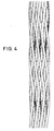
- FIG. 4 is an example of enlarging the basic pattern, comprising seven lines and three-wire plies.
- the principle of the 2,5D reinforcement consists in interlacing the warp and weft threads in order to obtain an indelaminable material, without thread perpendicular to the wall.
- Figures 1 to 3 show how the warp threads are arranged in relation to "circles” which correspond to the location of the weft threads. It will be noted that these weft threads, or these "circles” are arranged in staggered rows, forming alignments in rows and columns of which one intersection in two comprises a "circle” if each "circle” is given a line number and a column number: R indicates the "circle” of the 2nd column and the 3rd row. It will be noted that the total number of lines depends on the thickness of the material to be produced and that it is odd (here 5) while the number of columns is a multiple of 6, because the rest of the reinforcement is obtained by repeating the previous pattern.
- a set of pairs of parallel wires will be called "tablecloth".
- a complete pattern consists of 6 layers of warp threads, parallel two by two.
- FIG. 1 shows the path of the layers C1, C2 and C3
- FIG. 2 shows the path of the layers C4, C5 and C6.
- the tablecloth has only 2 threads and the number of threads of a tablecloth is equal to half the even number, immediately less than the number of lines.
- the first wire of the C1 ribbon cable passes over and below
- the second wire of the ribbon cable C1 passes over and below
- the first thread turns around then . It therefore connects one in three of the wires in line 2.
- the second thread revolves around then . It therefore connects one in three of the weft yarns in line 3 to one in three of the weft yarns in line 4.
- weft threads of line 1 are connected to those of line 2 and the weft threads of line 3 to those of line 4.
- the layers C4, C5 and C6 (FIG. 2) connect the weft threads of line 2 to those of line 3 and the weft threads of line 4 to those of line 5.
- the path of C4 is deduced from that of the water table C1 by adding 1 to the line number and 1 to the number of weft thread column.
- the pattern constituting this reinforcement is the simplest and most logical to obtain a material with interlaced layers.
- Each warp thread connects two rows of adjacent wefts.
- the arrangement of the weft threads (R) in staggered rows is imposed to avoid a vacuum between the warp threads and to minimize the undulations of the warp threads.
- the reinforcements according to the invention can be produced with fibers or threads of any kind (carbon, Kevlar, silica, silicon carbide, Nextel, etc.).
- These reinforcements are either made with fibers, or of the same kind, or else by a combination of fibers or threads of different natures.
- the sections of the fibers or threads can be identical or of different dimensions and shapes.
- the mesh of the frame can be adapted to the request by provision provided in advance of the "circles" corresponding to the weft threads.
- the reinforcement according to the invention can be produced in the form of a plate.
- most of this type of product relates to circular parts of variable shape, and is particularly suitable for thin structures.
Landscapes
- Engineering & Computer Science (AREA)
- Textile Engineering (AREA)
- Woven Fabrics (AREA)
- Wrappers (AREA)
- Agricultural Chemicals And Associated Chemicals (AREA)
- Reinforced Plastic Materials (AREA)
- Laminated Bodies (AREA)
- Building Environments (AREA)
- Compositions Of Macromolecular Compounds (AREA)
Abstract
Description
La présente invention concerne les matériaux composites et elle est plus particulièrement relative à une armature tissée ayant une texture nouvelle pour la fabrication de pièces à très haute résistance.The present invention relates to composite materials and it relates more particularly to a woven reinforcement having a new texture for the manufacture of parts with very high resistance.
Les matériaux composites présentent d'une façon générale les deux avantages suivants :
- - Caractéristiques, notamment mécaniques, exceptionnelles
- - Aptitudes remarquables à orienter les constituants dans les directions des contraintes auxquelles est soumise la structure, à telle enseigne que celle-ci possède des caractéristiques inégalables.
- - Characteristics, particularly mechanical, exceptional
- - Remarkable aptitudes to orient the constituents in the directions of the constraints to which the structure is subjected, so much so that it has incomparable characteristics.
Les matériaux composites sont constitués par une armature et un liant. L'armature est essentiellement réalisée à partir de fibres textiles très résistantes (fibres de verre, de silice, de carbone, de carbure de silicium, d'alumine, de polyamide aromatique, etc...) et le liant peut être une résine organique ou un produit réfractaire ou un métal.The composite materials consist of a reinforcement and a binder. The frame is essentially made from very resistant textile fibers (glass fibers, silica fibers, carbon fibers, silicon carbide fibers, alumina fibers, aromatic polyamide fibers, etc.) and the binder can be an organic resin. or a refractory product or a metal.
La présente invention a pour but de réaliser un nouveau type d'armature. Telle que réalisée selon l'invention, l'armature est dite tissée. On entend par armature tissée, un entrelacement de fibres textiles qui se tient par lui-même et a les caractéristiques dimensionnelles de la pièce en matériau composite.The present invention aims to achieve a new type of frame. As produced according to the invention, the frame is said to be woven. By woven reinforcement is meant an interlacing of textile fibers which stands by itself and has the dimensional characteristics of the part made of composite material.
Le liant nécessaire à la finition de la structure peut être déposé dans l'armature tissée, soit par voie liquide, soit par voie gazeuse. La voie liquide consiste à faire pénétrer dans l'armature un imprégnant liquide qui, par un traitement ultérieur, se transforme à telle enseigne que la structure ainsi confectionnée possède les caractéristiques requises. Par la voie gazeuse, on entend un procédé tel que l'armature est placée dans une enceinte à température et pression fixées et est soumise de façon concomitante à un flux gazeux dont les molécules se décomposent au contact des fibres constituant l'armature (dépôt chimique en phase vapeur). Au bout d'un certain temps, l'armature plus le liant ont obtenu les caractéristiques requises.The binder required to finish the structure can be deposited in the woven reinforcement, either by liquid or by gas. The liquid route consists in making a liquid impregnate penetrate into the reinforcement which, by subsequent treatment, is transformed to such an extent that the structure thus made up has the required characteristics. By the gaseous route is meant a process such that the armature is placed in an enclosure at a fixed temperature and pressure and is subjected concomitantly to a gas flow, the molecules of which decompose in contact with the fibers constituting the armature (chemical deposition vapor phase). After a certain time, the reinforcement plus the binder have obtained the required characteristics.
La littérature décrit des armatures comportant des renforts dans différentes directions :The literature describes reinforcements with reinforcements in different directions:
C'est notamment le cas des feutres. Ces armatures présentent l'avantage d'avoir des caractéristiques très homogènes. Elles présentent l'inconvénient souvent rédhibitoire d'avoir des caractéristiques mécaniques faibles dues au fait que les fibres sont courtes (inférieures à 1 centimètre) et peu liées les unes aux autres par le liant.This is particularly the case with felts. These reinforcements have the advantage of having very homogeneous characteristics. They often have the unacceptable disadvantage of having weak mechanical characteristics due to the fact that the fibers are short (less than 1 centimeter) and little linked to each other by the binder.
Des armatures de ce type sont la plupart du temps utilisées comme sous-produits des armatures à plus d'une direction (à l'exception des aléas D) ou dans l'industrie des sports et loisirs. Elles sont constituées par des fibres longues (plusieurs mètres) alignées parallèlement les unes aux autres.Armatures of this type are most often used as by-products of armatures in more than one direction (with the exception of hazards D) or in the sports and leisure industry. They consist of long fibers (several meters) aligned parallel to each other.
Il s'agit de toutes les sortes de tissus et des produits bobinés. Ces tissus sont utilisés à l'état de monocouches, essentiellement dans l'industrie du vêtement. Dans la plupart des autres industries, les 2D sont utilisées à l'état de multicouches. Les structures résultantes ont d'excellentes caractéristiques mécaniques dans le sens des renforts. Par contre, dans le sens perpendiculaire, les caractéristiques sont très faibles, à telle enseigne que des clivages intercouches (aussi appelés délaminages) peuvent se produire en cours de dépôt du liant, lors d'un choc ou lors de sollicitations cycliques, souvent rédhibitoires pour l'utilisation envisagée.These are all kinds of fabrics and wound products. These fabrics are used as monolayers, mainly in the clothing industry. In most other industries, 2D is used as a multilayer. The resulting structures have excellent mechanical characteristics in the direction of the reinforcements. On the other hand, in the perpendicular direction, the characteristics are very weak, so much so that interlayer cleavages (also called delaminations) can occur during deposition of the binder, during an impact or during cyclic stresses, often prohibitive for the intended use.
Il s'agit là de produits beaucoup plus sophistiqués dont l'utilisation est essentiellement réservée à l'heure actuelle aux secteurs aéronautiques et balistiques. Les structures résultantes ont d'excellentes caractéristiques, notamment dans les trois directions des fibres de renfort. D'autre part, elles ne présentent pas de risque de délaminage.These are much more sophisticated products, the use of which is mainly reserved at present for the aeronautical and ballistic sectors. The resulting structures have excellent characteristics, especially in the three directions of the reinforcing fibers. On the other hand, they do not present a risk of delamination.
Les fibres de renforts peuvent être disposées, soit selon les trois axes d'un trièdre normal (3D triorthogonal), soit selon des directions radiales, circonférentielles et longitudinales des pièces axisymétri- ques (3D polaire).The reinforcing fibers can be arranged either along the three axes of a normal trihedron (triorthogonal 3D), or along radial, circumferential and longitudinal directions of the axisymmetric parts (polar 3D).
L'inconvénient des armatures 3D est que, telles qu'obtenues par les procédés existants à ce jour, l'espacement entre les couches des fils est trop grand pour répondre aux besoins des structures minces, lesquelles peuvent être de l'ordre de 1 à 3 mm. Par ailleurs, du fait de sa construction géométrique, le 3D possède des grandes cavités. Celles-ci compliquent le plus souvent l'opération de dépôt du liant de façon homogène, tant par voie liquide, que par voie gazeuse.The disadvantage of 3D reinforcement is that, as obtained by existing methods to date, the spacing between the layers of the wires is too large to meet the needs of thin structures, which can be of the order of 1 to 3 mm. In addition, due to its geometric construction, the 3D has large cavities. These most often complicate the operation of depositing the binder in a homogeneous manner, both liquid and gas.
Il existe de nombreux procédés permettant de réaliser des armatures fibreuses. Certains de ces procédés sont dans le domaine public; d'autres sont protégés par des brevets d'invention, par exemple les brevets FR-2 395 340 et FR-2 531 459 de la demanderesse.There are many methods for making fibrous reinforcements. Some of these processes are in the public domain; others are protected by invention patents, for example the applicants' patents FR-2,395,340 and FR-2,531,459.
Il existe des armatures à plus de trois dimensions (4D, 5D, 9D et 11 D). Elles ont l'avantage d'avoir de bonnes caractéristiques homogènes. Toutefois, leur utilisation est très marginale, du fait notamment de l'extrême complexité de leur réalisation par des procédés automatiques.There are reinforcements with more than three dimensions (4D, 5D, 9D and 11 D). They have the advantage of having good homogeneous characteristics. However, their use is very marginal, due in particular to the extreme complexity of their production by automatic methods.
Le but de l'invention est de fournir une armature nouvelle particulièrement appropriée pour la réalisation de structure minces et notamment pour des éléments de protection d'engins spatiaux lors de leur rentrée dans l'atmosphère, ou autres applications, présentant de très bonnes caractéristiques mécaniques dans le sens des renforts, équivalent à un empilement de 2D, indélaminable comme un 3D, mais sans fibres perpendiculaires à la paroi, c'est-à-dire une armature intermédiaire entre le 2D et le 3D.The object of the invention is to provide a new reinforcement which is particularly suitable for producing thin structures and in particular for elements for protecting spacecraft when they re-enter the atmosphere, or other applications, having very good mechanical characteristics. in the direction of the reinforcements, equivalent to a stack of 2D, indelaminable like a 3D, but without fibers perpendicular to the wall, that is to say an intermediate reinforcement between 2D and 3D.
L'invention a pour objet à cet effet une armature en fils ou fibres tissés formée de fils de trame et de fils de chaîne, caractérisée en ce que sa texture est formée par un motif de base constitué par quinze fils de trame R disposés en quinconces formant six colonnes verticales 1 à 6 de deux et trois fils alternativement et au moins cinq lignes horizontales 1 à 5 de trois fils chacune, et par six nappes imbriquées C1 à C6 d'au moins deux fils parallèles soit au moins douze fils a, b, c...l, reliant chacun un fil de trame sur trois d'une même colonne dans deux lignes adjacentes et les fils de chaîne des nappes consécutives reliant des fils de trame dans des colonnes alternées, le premier fil a de la première nappe C1 reliant le fil de trame R de la colonne 2, dans la ligne 1, soit ![]()
![]()
![]()
![]()
![]()
![]()
![]()

![]()
![]()
![]()
![]()
![]()
![]()
![]()
La figure 4 est un exemple d'agrandissement du motif de base, comportant sept lignes et des nappes de trois fils.FIG. 4 is an example of enlarging the basic pattern, comprising seven lines and three-wire plies.
La description qui va suivre, en regard des dessins annexés à titre d'exemples non limitatifs, permettra de bien comprendre comment l'invention peut être mise en pratique.
- La figure 1 est une vue schématique d'une première partie d'un motif de base d'une armature suivant l'invention montrant l'agencement des six fils de chaîne a...f des trois premières nappes C1, C2, C3 par rapport aux fils de trame R.
- La figure 2 est une vue analogue à celle de la figure 1, montrant l'agencement des six fils de chaîne g...l des trois autres nappes C4, C5 et C6 par rapport aux fils de trame du même motif de base.
- la figure 3 est une vue schématique d'un motif de bae complet, obtenue par superposition des figures 1 et 2.
- La figure 4 montre l'agencement réel des fils de chaîne et de trame dans l'armature suivant l'invention, tel qu'il apparait à la micrographie.
- Figure 1 is a schematic view of a first part of a basic pattern of a frame according to the invention showing the arrangement of the six warp son a ... f of the first three plies C1, C2, C3 by compared to the weft threads R.
- Figure 2 is a view similar to that of Figure 1, showing the arrangement of the six warp son g ... l of the other three plies C4, C5 and C6 with respect to the weft son of the same basic pattern.
- FIG. 3 is a schematic view of a complete bae pattern, obtained by superposition of FIGS. 1 and 2.
- FIG. 4 shows the actual arrangement of the warp and weft threads in the reinforcement according to the invention, as it appears on the micrograph.
Le principe de l'armature 2,5D consiste à entrelacer les fils de chaîne et les fils de trame afin d'obtenir un matériau indélaminable, sans fil perpendiculaire à la paroi.The principle of the 2,5D reinforcement consists in interlacing the warp and weft threads in order to obtain an indelaminable material, without thread perpendicular to the wall.
Les figures 1 à 3 montrent comment les fils de chaîne sont disposés par rapport à des "ronds" qui correspondent à l'emplacement des fils de trame. On notera que ces fils de trame, ou ces "ronds" sont disposés en quinconce, formant des alignements en lignes et colonnes dont une Intersection sur deux comporte un "rond" si l'on donne à chaque "rond" un numéro de ligne et un numéro de colonne : R désigne le "rond" de la 2ème colonne et de la 3ème ligne. On notera que le nombre total de lignes dépend de l'épaisseur du matériau à réaliser et qu'il est impair (ici 5) alors que le nombre de colonne est multiple de 6, car le reste de l'armature est obtenu par répétition du motif précédent.Figures 1 to 3 show how the warp threads are arranged in relation to "circles" which correspond to the location of the weft threads. It will be noted that these weft threads, or these "circles" are arranged in staggered rows, forming alignments in rows and columns of which one intersection in two comprises a "circle" if each "circle" is given a line number and a column number: R indicates the "circle" of the 2nd column and the 3rd row. It will be noted that the total number of lines depends on the thickness of the material to be produced and that it is odd (here 5) while the number of columns is a multiple of 6, because the rest of the reinforcement is obtained by repeating the previous pattern.
On appelera "nappe" un ensemble de paires de fils parallèles. Un motif complet est constitué de 6 nappes de fils de chaîne, parallèles deux à deux.A set of pairs of parallel wires will be called "tablecloth". A complete pattern consists of 6 layers of warp threads, parallel two by two.
On désignera ces nappes par C1, C2, C3, C4, C5 et C6. (Pour plus de clarté, le trajet de ces nappes a été séparé en deux figures). La figure 1 montre le trajet des nappes C1, C2 et C3, et la figure 2, montre le trajet des napes C4, C5 et C6.These layers will be designated by C1, C2, C3, C4, C5 and C6. (For clarity, the path of these layers has been separated into two figures). FIG. 1 shows the path of the layers C1, C2 and C3, and FIG. 2 shows the path of the layers C4, C5 and C6.
Sur le motif représenté, la nappe comporte seulement 2 fils et le nombre de fils d'une nappe est égal à la moitié du nombre pair, immédiatement inférieur au nombre de lignes.On the pattern shown, the tablecloth has only 2 threads and the number of threads of a tablecloth is equal to half the even number, immediately less than the number of lines.
Le premier fil de la nappe C1 passe au-dessus de ![]()
![]()
![]()
![]()
Le deuxième fil de la nappe C1 passe au-dessus de ![]()
![]()
![]()
![]()
Le premier fil tourne autour de ![]()
![]()
![]()
![]()
Le deuxième fil tourne autour de ![]()
![]()
![]()
![]()
En ajoutant 2 au numéro de colonne des fils de trame, on obtient le trajet des fils de la nappe C2, puis en y ajoutant à nouveau 2, celui de la nappe C3.By adding 2 to the column number of the weft threads, the path of the threads of the sheet C2 is obtained, then by adding 2 again, that of the sheet C3.
Quand ces 3 nappes sont passées, les fils de trame de la ligne 1 sont reliés à ceux de la ligne 2 et les fils de trame de la ligne 3 à ceux de la ligne 4.When these 3 layers have passed, the weft threads of
Les nappes C4, C5 et C6 (figure 2) relient les fils de trame de la ligne 2 à ceux de la ligne 3 et les fils de trame de la ligne 4 à ceux de la ligne 5.The layers C4, C5 and C6 (FIG. 2) connect the weft threads of
Le trajet de C4 est déduit de celui de la nappe C1 en ajoutant 1 au numéro de ligne et 1 au numéro de colonne des fils de trame.The path of C4 is deduced from that of the water table C1 by adding 1 to the line number and 1 to the number of weft thread column.
La présentation réelle du produit obtenu est représentée à la figure 3. On notera la forme en ovale aplati que prennent les fils de trame et le fort pourcentage de la surface occupée par des filaments; ceci est favorable à la tenue mécanique du matériau et facilite la mise en place du liant.The actual presentation of the product obtained is shown in Figure 3. Note the flattened oval shape of the weft threads and the high percentage of the area occupied by filaments; this is favorable to the mechanical strength of the material and facilitates the placement of the binder.
Le motif constituant cette armature est le plus simple et le plus logique pour obtenir un matériau à couches entrelacées.The pattern constituting this reinforcement is the simplest and most logical to obtain a material with interlaced layers.
Chaque fil de chaîne relie deux rangées de trames adjacentes. La disposition des fils de trame (R) en quinconce est imposée pour éviter un vide entre les fils de chaîne et minimiser les ondulations des fils de chaîne.Each warp thread connects two rows of adjacent wefts. The arrangement of the weft threads (R) in staggered rows is imposed to avoid a vacuum between the warp threads and to minimize the undulations of the warp threads.
Dans ce motif il faut 6 nappes de fil pour lier les rangées de fils de fils de trame.In this pattern you need 6 layers of thread to tie the rows of weft threads.
Les armatures suivant l'invention peuvent être réalisées avec des fibres ou fils de toute nature (carbone, Kevlar, silice, carbure de silicium, Nextel...).The reinforcements according to the invention can be produced with fibers or threads of any kind (carbon, Kevlar, silica, silicon carbide, Nextel, etc.).
Ces armatures sont soit réalisées avec des fibres, soit de même nature, soit encore par combinaison de fibres ou fils de natures différentes. De plus les sections des fibres ou fils peuvent être identiques ou de dimensions et formes différentes.These reinforcements are either made with fibers, or of the same kind, or else by a combination of fibers or threads of different natures. In addition, the sections of the fibers or threads can be identical or of different dimensions and shapes.
Enfin, le maillage de l'armature peut être adapté à la demande par disposition prévue à l'avance des "ronds" correspondants aux fils de trame.Finally, the mesh of the frame can be adapted to the request by provision provided in advance of the "circles" corresponding to the weft threads.
L'armature suivant l'invention peut être réalisée sous forme de plaque. Cependant, la majeure partie de ce type de produit concerne des pièces circulaires de forme variable, et convient en particulier pour les structures minces.The reinforcement according to the invention can be produced in the form of a plate. However, most of this type of product relates to circular parts of variable shape, and is particularly suitable for thin structures.
Claims (1)

Priority Applications (1)
| Application Number | Priority Date | Filing Date | Title |
|---|---|---|---|
| AT88400279T ATE58923T1 (en) | 1987-02-17 | 1988-02-08 | WOVEN REINFORCEMENT FOR COMPOSITE BUILDING MATERIAL. |
Applications Claiming Priority (2)
| Application Number | Priority Date | Filing Date | Title |
|---|---|---|---|
| FR8702012A FR2610951B1 (en) | 1987-02-17 | 1987-02-17 | WOVEN REINFORCEMENT FOR COMPOSITE MATERIAL |
| FR8702012 | 1987-02-17 |
Publications (2)
| Publication Number | Publication Date |
|---|---|
| EP0283334A1 true EP0283334A1 (en) | 1988-09-21 |
| EP0283334B1 EP0283334B1 (en) | 1990-12-05 |
Family
ID=9348001
Family Applications (1)
| Application Number | Title | Priority Date | Filing Date |
|---|---|---|---|
| EP88400279A Expired - Lifetime EP0283334B1 (en) | 1987-02-17 | 1988-02-08 | Woven reinforcement for composite material |
Country Status (11)
| Country | Link |
|---|---|
| US (1) | US4848414A (en) |
| EP (1) | EP0283334B1 (en) |
| JP (1) | JPS63295740A (en) |
| AT (1) | ATE58923T1 (en) |
| CA (1) | CA1301593C (en) |
| DE (1) | DE3861199D1 (en) |
| DK (1) | DK164821C (en) |
| ES (1) | ES2018880B3 (en) |
| FR (1) | FR2610951B1 (en) |
| IE (1) | IE60050B1 (en) |
| NO (1) | NO163457C (en) |
Cited By (1)
| Publication number | Priority date | Publication date | Assignee | Title |
|---|---|---|---|---|
| EP0493196A1 (en) * | 1990-12-28 | 1992-07-01 | Société Industrielle des Ets L.A. CHAIGNAUD-S.I.L.A.C. | Threedimensional fabric and process of manufacturing thereof |
Families Citing this family (23)
| Publication number | Priority date | Publication date | Assignee | Title |
|---|---|---|---|---|
| FR2653141B1 (en) * | 1989-10-16 | 1992-04-17 | Chaignaud Ind | COMPOSITE MATERIAL AND ITS MANUFACTURING METHOD. |
| FR2686336B1 (en) * | 1992-01-20 | 1995-01-13 | Aerospatiale | CARBON-CARBON COMPOSITE MATERIAL HAVING OXIDATION RESISTANT MATRIX SIC AND METHOD FOR THE PRODUCTION THEREOF. |
| FR2691174B1 (en) * | 1992-05-15 | 1994-07-29 | Aerospatiale | METHOD FOR WEAVING THICK REINFORCEMENT WITH INDELAMINABLE MULTIPLE LAYERS FOR COMPOSITE MATERIALS AND WEAVING MACHINE FOR IMPLEMENTING SAME. |
| FR2702222B1 (en) * | 1993-03-03 | 1995-05-05 | Cotton Freres Cie | Three-dimensional multiaxial fabric and its manufacturing process. |
| US5616175A (en) * | 1994-07-22 | 1997-04-01 | Herecules Incorporated | 3-D carbon-carbon composites for crystal pulling furnace hardware |
| FR2732406B1 (en) * | 1995-03-29 | 1997-08-29 | Snecma | BLADE OF TURBOMACHINE IN COMPOSITE MATERIAL |
| FR2750170B1 (en) * | 1996-06-24 | 1998-08-21 | Aerospatiale | FUEL INJECTION MAT FOR STATOREACTOR OPERATING AT A HIGH NUMBER OF MACH |
| FR2753993B1 (en) | 1996-10-01 | 1998-11-27 | Aerospatiale | BRAIDED TUBULAR STRUCTURE FOR COMPOSITE PIECE, ITS REALIZATION AND ITS APPLICATIONS |
| FR2759096B1 (en) * | 1997-02-04 | 1999-02-26 | Snecma | LINKED MULTILAYER TEXTURE FOR STRUCTURAL COMPOSITE MATERIALS |
| SE9901572D0 (en) * | 1999-05-03 | 1999-05-03 | Astra Ab | New compounds |
| GB2362388B (en) * | 2000-05-15 | 2004-09-29 | Smith International | Woven and packed composite constructions |
| FR2819804B1 (en) * | 2001-01-24 | 2003-04-25 | Eads Launch Vehicles | PROCESS FOR MANUFACTURING A CARBON / CARBON PART |
| FR2825699A1 (en) | 2001-06-12 | 2002-12-13 | Eads Launch Vehicles | Densification and anti-corrosion treatment of a thermostructural composite material includes chemical vapor phase infiltration with carbon and/or silicon carbide molecules |
| FR2861143B1 (en) * | 2003-10-20 | 2006-01-20 | Snecma Moteurs | TURBOMACHINE BLADE, IN PARTICULAR BLADE OF BLOWER AND METHOD OF MANUFACTURING THE SAME |
| FR2876946B1 (en) | 2004-10-27 | 2007-02-02 | Eads Space Transp Sas Soc Par | INSERT IN COMPOSITE MATERIAL AND METHOD FOR MANUFACTURING SAME, AND METHOD FOR PRODUCING SANDWICH STRUCTURE COMPRISING SUCH INSERT |
| FR2902803B1 (en) * | 2006-06-21 | 2008-11-14 | Snecma Propulsion Solide Sa | FIBROUS REINFORCING STRUCTURE FOR A PIECE OF COMPOSITE MATERIAL AND PART COMPRISING THE SAME |
| FR2907475B1 (en) * | 2006-10-18 | 2008-12-05 | Messier Dowty Sa Sa | 3D COMPOSITE FABRIC |
| FR2917099B1 (en) * | 2007-06-06 | 2010-03-19 | Ensait | METHOD FOR MANUFACTURING A COMPOSITE MATERIAL, IN PARTICULAR FOR BALLISTIC PROTECTION, AND COMPOSITE MATERIAL OBTAINED |
| JP2009203092A (en) | 2008-02-26 | 2009-09-10 | Ibiden Co Ltd | Vessel holding member |
| US7963747B2 (en) * | 2009-04-02 | 2011-06-21 | General Electric Company | Braided wind turbine blades and method of making same |
| US9181642B2 (en) * | 2012-12-07 | 2015-11-10 | Vostech B.V. | Triaxial textile armature, process for producing triaxial textile armatures and composite material part |
| CN104802982B (en) * | 2015-04-22 | 2016-10-12 | 北京航空航天大学 | D braided composites global formation rotor blade and preparation method thereof |
| FR3098544B1 (en) | 2019-07-11 | 2021-06-25 | Safran Aircraft Engines | Blower blade |
Citations (4)
| Publication number | Priority date | Publication date | Assignee | Title |
|---|---|---|---|---|
| FR2395340A1 (en) * | 1977-06-20 | 1979-01-19 | Aerospatiale | THREE-DIMENSIONAL WEAVING PROCESS AND MACHINE FOR THE REALIZATION OF HOLLOW REVOLUTIONS WOVEN REINFORCEMENTS |
| US4174739A (en) * | 1978-02-21 | 1979-11-20 | Fenner America Ltd. | Tubular fabric |
| EP0101351A2 (en) * | 1982-08-09 | 1984-02-22 | AEROSPATIALE Société Nationale Industrielle | Process and machine for making a complex fabric by multidirectional weaving |
| DE3434115A1 (en) * | 1984-09-17 | 1986-04-03 | Clouth Gummiwerke AG, 5000 Köln | Conveyor belt |
Family Cites Families (2)
| Publication number | Priority date | Publication date | Assignee | Title |
|---|---|---|---|---|
| US2866483A (en) * | 1954-06-01 | 1958-12-30 | Fenner Co Ltd J H | Textile materials for power transmission and conveyor belting |
| US4312913A (en) * | 1980-05-12 | 1982-01-26 | Textile Products Incorporated | Heat conductive fabric |
-
1987
- 1987-02-17 FR FR8702012A patent/FR2610951B1/en not_active Expired
-
1988
- 1988-02-08 AT AT88400279T patent/ATE58923T1/en not_active IP Right Cessation
- 1988-02-08 DE DE8888400279T patent/DE3861199D1/en not_active Expired - Lifetime
- 1988-02-08 EP EP88400279A patent/EP0283334B1/en not_active Expired - Lifetime
- 1988-02-08 ES ES88400279T patent/ES2018880B3/en not_active Expired - Lifetime
- 1988-02-10 CA CA000558571A patent/CA1301593C/en not_active Expired - Lifetime
- 1988-02-10 IE IE36688A patent/IE60050B1/en not_active IP Right Cessation
- 1988-02-15 DK DK075888A patent/DK164821C/en not_active IP Right Cessation
- 1988-02-16 JP JP63031962A patent/JPS63295740A/en active Granted
- 1988-02-16 NO NO880680A patent/NO163457C/en not_active IP Right Cessation
- 1988-02-17 US US07/157,325 patent/US4848414A/en not_active Expired - Lifetime
Patent Citations (4)
| Publication number | Priority date | Publication date | Assignee | Title |
|---|---|---|---|---|
| FR2395340A1 (en) * | 1977-06-20 | 1979-01-19 | Aerospatiale | THREE-DIMENSIONAL WEAVING PROCESS AND MACHINE FOR THE REALIZATION OF HOLLOW REVOLUTIONS WOVEN REINFORCEMENTS |
| US4174739A (en) * | 1978-02-21 | 1979-11-20 | Fenner America Ltd. | Tubular fabric |
| EP0101351A2 (en) * | 1982-08-09 | 1984-02-22 | AEROSPATIALE Société Nationale Industrielle | Process and machine for making a complex fabric by multidirectional weaving |
| DE3434115A1 (en) * | 1984-09-17 | 1986-04-03 | Clouth Gummiwerke AG, 5000 Köln | Conveyor belt |
Cited By (2)
| Publication number | Priority date | Publication date | Assignee | Title |
|---|---|---|---|---|
| EP0493196A1 (en) * | 1990-12-28 | 1992-07-01 | Société Industrielle des Ets L.A. CHAIGNAUD-S.I.L.A.C. | Threedimensional fabric and process of manufacturing thereof |
| FR2671111A1 (en) * | 1990-12-28 | 1992-07-03 | Chaignaud Silac Ets L A | MULTICHAIN TEXTILE STRUCTURE WOVEN IN THREE DIMENSIONS AND METHOD FOR MANUFACTURING THE SAME. |
Also Published As
| Publication number | Publication date |
|---|---|
| NO880680D0 (en) | 1988-02-16 |
| JPH0359175B2 (en) | 1991-09-09 |
| DE3861199D1 (en) | 1991-01-17 |
| DK75888D0 (en) | 1988-02-15 |
| ATE58923T1 (en) | 1990-12-15 |
| US4848414A (en) | 1989-07-18 |
| NO163457C (en) | 1990-05-30 |
| CA1301593C (en) | 1992-05-26 |
| IE880366L (en) | 1988-08-17 |
| NO163457B (en) | 1990-02-19 |
| ES2018880B3 (en) | 1991-05-16 |
| NO880680L (en) | 1988-08-18 |
| FR2610951A1 (en) | 1988-08-19 |
| EP0283334B1 (en) | 1990-12-05 |
| FR2610951B1 (en) | 1989-05-05 |
| DK164821C (en) | 1993-01-11 |
| DK164821B (en) | 1992-08-24 |
| JPS63295740A (en) | 1988-12-02 |
| IE60050B1 (en) | 1994-05-18 |
| DK75888A (en) | 1988-08-18 |
Similar Documents
| Publication | Publication Date | Title |
|---|---|---|
| EP0283334B1 (en) | Woven reinforcement for composite material | |
| EP0303534B1 (en) | Textile structure for making stratified products with great mechanical properties | |
| EP0032858B1 (en) | Tridimensional annular structure | |
| KR101387890B1 (en) | Fibrous reinforcement structure for producing a composite part | |
| EP0056351B1 (en) | Three-dimensional woven fabric for reinforcing stratified materials, and shaped elements obtained with this fabric | |
| EP0031785B1 (en) | Complex textile material for making stratified products and stratified products made from this material | |
| EP2089565B1 (en) | 3d composite fabric | |
| EP2032751B1 (en) | Fibrous reinforcement structure of multi-satin weave for a composite part | |
| EP0270411B1 (en) | Textile structure for the manufacture of stratified composite articles by injection moulding | |
| FR2602248A1 (en) | MULTI-DIMENSIONAL TEXTILE STRUCTURE FOR STRENGTHENING LAMINATED MATERIALS AND METHOD AND WORKING MACHINE FOR OBTAINING SUCH A STRUCTURE | |
| EP1893399A2 (en) | Reinforcing fibrous structure for a composite material and a part containing said structure | |
| EP0118373B1 (en) | Open-work textile structure and its method of manufacture | |
| EP0056352A1 (en) | Multilayer textile web for the reinforcement of layered products, and process for making it | |
| FR2759096A1 (en) | BONDED MULTILAYER TEXTURE FOR STRUCTURAL COMPOSITE MATERIALS | |
| FR2650367A1 (en) | HIGH PRESSURE BOTTLE WITH THIN METALLIC WALLS REINFORCED BY A COIL FIBER WINDING, AND METHOD FOR MANUFACTURING THE SAME | |
| WO1990012911A1 (en) | Deformable textile structure | |
| FR2713663A1 (en) | Fabrication of axisymmetrical composite components | |
| FR2705370A1 (en) | Ultra-high performance carbon-based composites, fabrics and preforms, and process for their manufacture | |
| JPH03227806A (en) | Belt for forming non-woven cloth | |
| EP0687315B1 (en) | Multiaxial three-dimensional fabric and process for its manufacture | |
| WO2014128419A1 (en) | Method for weaving a dual-apertured multilayer fabric | |
| EP0493196B1 (en) | Threedimensional fabric and process of manufacturing thereof | |
| CN1198676C (en) | Plane metal structure, especially for filtration and method for producing plane structure as well as the use of plane structure | |
| FR2580987A1 (en) | Method for implanting rigid elements on the surface of a body and application to the manufacture of multi-directional textures especially for composite materials |
Legal Events
| Date | Code | Title | Description |
|---|---|---|---|
| PUAI | Public reference made under article 153(3) epc to a published international application that has entered the european phase |
Free format text: ORIGINAL CODE: 0009012 |
|
| 17P | Request for examination filed |
Effective date: 19880211 |
|
| AK | Designated contracting states |
Kind code of ref document: A1 Designated state(s): AT BE CH DE ES GB IT LI NL SE |
|
| 17Q | First examination report despatched |
Effective date: 19900511 |
|
| GRAA | (expected) grant |
Free format text: ORIGINAL CODE: 0009210 |
|
| ITF | It: translation for a ep patent filed | ||
| AK | Designated contracting states |
Kind code of ref document: B1 Designated state(s): AT BE CH DE ES GB IT LI NL SE |
|
| REF | Corresponds to: |
Ref document number: 58923 Country of ref document: AT Date of ref document: 19901215 Kind code of ref document: T |
|
| REF | Corresponds to: |
Ref document number: 3861199 Country of ref document: DE Date of ref document: 19910117 |
|
| GBT | Gb: translation of ep patent filed (gb section 77(6)(a)/1977) | ||
| PLBE | No opposition filed within time limit |
Free format text: ORIGINAL CODE: 0009261 |
|
| STAA | Information on the status of an ep patent application or granted ep patent |
Free format text: STATUS: NO OPPOSITION FILED WITHIN TIME LIMIT |
|
| 26N | No opposition filed | ||
| ITTA | It: last paid annual fee | ||
| EAL | Se: european patent in force in sweden |
Ref document number: 88400279.1 |
|
| REG | Reference to a national code |
Ref country code: GB Ref legal event code: IF02 |
|
| PGFP | Annual fee paid to national office [announced via postgrant information from national office to epo] |
Ref country code: SE Payment date: 20040216 Year of fee payment: 17 |
|
| PGFP | Annual fee paid to national office [announced via postgrant information from national office to epo] |
Ref country code: AT Payment date: 20040227 Year of fee payment: 17 Ref country code: NL Payment date: 20040227 Year of fee payment: 17 |
|
| PGFP | Annual fee paid to national office [announced via postgrant information from national office to epo] |
Ref country code: BE Payment date: 20040312 Year of fee payment: 17 |
|
| PGFP | Annual fee paid to national office [announced via postgrant information from national office to epo] |
Ref country code: CH Payment date: 20040503 Year of fee payment: 17 |
|
| PG25 | Lapsed in a contracting state [announced via postgrant information from national office to epo] |
Ref country code: AT Free format text: LAPSE BECAUSE OF NON-PAYMENT OF DUE FEES Effective date: 20050208 |
|
| PG25 | Lapsed in a contracting state [announced via postgrant information from national office to epo] |
Ref country code: SE Free format text: LAPSE BECAUSE OF NON-PAYMENT OF DUE FEES Effective date: 20050209 |
|
| PG25 | Lapsed in a contracting state [announced via postgrant information from national office to epo] |
Ref country code: LI Free format text: LAPSE BECAUSE OF NON-PAYMENT OF DUE FEES Effective date: 20050228 Ref country code: BE Free format text: LAPSE BECAUSE OF NON-PAYMENT OF DUE FEES Effective date: 20050228 Ref country code: CH Free format text: LAPSE BECAUSE OF NON-PAYMENT OF DUE FEES Effective date: 20050228 |
|
| BERE | Be: lapsed |
Owner name: *AEROSPATIALE SOC. NATIONALE INDUSTRIELLE Effective date: 20050228 |
|
| PG25 | Lapsed in a contracting state [announced via postgrant information from national office to epo] |
Ref country code: NL Free format text: LAPSE BECAUSE OF NON-PAYMENT OF DUE FEES Effective date: 20050901 |
|
| EUG | Se: european patent has lapsed | ||
| REG | Reference to a national code |
Ref country code: CH Ref legal event code: PL |
|
| NLV4 | Nl: lapsed or anulled due to non-payment of the annual fee |
Effective date: 20050901 |
|
| PGFP | Annual fee paid to national office [announced via postgrant information from national office to epo] |
Ref country code: GB Payment date: 20070216 Year of fee payment: 20 Ref country code: DE Payment date: 20070216 Year of fee payment: 20 |
|
| PGFP | Annual fee paid to national office [announced via postgrant information from national office to epo] |
Ref country code: ES Payment date: 20070227 Year of fee payment: 20 |
|
| BERE | Be: lapsed |
Owner name: *AEROSPATIALE SOC. NATIONALE INDUSTRIELLE Effective date: 20050228 |
|
| PGFP | Annual fee paid to national office [announced via postgrant information from national office to epo] |
Ref country code: IT Payment date: 20070626 Year of fee payment: 20 |
|
| REG | Reference to a national code |
Ref country code: GB Ref legal event code: PE20 |
|
| REG | Reference to a national code |
Ref country code: ES Ref legal event code: FD2A Effective date: 20080209 |
|
| PG25 | Lapsed in a contracting state [announced via postgrant information from national office to epo] |
Ref country code: GB Free format text: LAPSE BECAUSE OF EXPIRATION OF PROTECTION Effective date: 20080207 |
|
| PG25 | Lapsed in a contracting state [announced via postgrant information from national office to epo] |
Ref country code: ES Free format text: LAPSE BECAUSE OF EXPIRATION OF PROTECTION Effective date: 20080209 |