EP0282836A2 - Process and apparatus for depositing of high ohmic resistance layers by cathodic sputtering - Google Patents
Process and apparatus for depositing of high ohmic resistance layers by cathodic sputtering Download PDFInfo
- Publication number
- EP0282836A2 EP0282836A2 EP88103333A EP88103333A EP0282836A2 EP 0282836 A2 EP0282836 A2 EP 0282836A2 EP 88103333 A EP88103333 A EP 88103333A EP 88103333 A EP88103333 A EP 88103333A EP 0282836 A2 EP0282836 A2 EP 0282836A2
- Authority
- EP
- European Patent Office
- Prior art keywords
- target
- substrate
- distance
- reaction gas
- shielding device
- Prior art date
- Legal status (The legal status is an assumption and is not a legal conclusion. Google has not performed a legal analysis and makes no representation as to the accuracy of the status listed.)
- Granted
Links
Images

Classifications
-
- H—ELECTRICITY
- H01—ELECTRIC ELEMENTS
- H01J—ELECTRIC DISCHARGE TUBES OR DISCHARGE LAMPS
- H01J37/00—Discharge tubes with provision for introducing objects or material to be exposed to the discharge, e.g. for the purpose of examination or processing thereof
- H01J37/32—Gas-filled discharge tubes
- H01J37/32431—Constructional details of the reactor
- H01J37/3244—Gas supply means
-
- C—CHEMISTRY; METALLURGY
- C23—COATING METALLIC MATERIAL; COATING MATERIAL WITH METALLIC MATERIAL; CHEMICAL SURFACE TREATMENT; DIFFUSION TREATMENT OF METALLIC MATERIAL; COATING BY VACUUM EVAPORATION, BY SPUTTERING, BY ION IMPLANTATION OR BY CHEMICAL VAPOUR DEPOSITION, IN GENERAL; INHIBITING CORROSION OF METALLIC MATERIAL OR INCRUSTATION IN GENERAL
- C23C—COATING METALLIC MATERIAL; COATING MATERIAL WITH METALLIC MATERIAL; SURFACE TREATMENT OF METALLIC MATERIAL BY DIFFUSION INTO THE SURFACE, BY CHEMICAL CONVERSION OR SUBSTITUTION; COATING BY VACUUM EVAPORATION, BY SPUTTERING, BY ION IMPLANTATION OR BY CHEMICAL VAPOUR DEPOSITION, IN GENERAL
- C23C14/00—Coating by vacuum evaporation, by sputtering or by ion implantation of the coating forming material
- C23C14/22—Coating by vacuum evaporation, by sputtering or by ion implantation of the coating forming material characterised by the process of coating
- C23C14/34—Sputtering
- C23C14/35—Sputtering by application of a magnetic field, e.g. magnetron sputtering
-
- H—ELECTRICITY
- H01—ELECTRIC ELEMENTS
- H01J—ELECTRIC DISCHARGE TUBES OR DISCHARGE LAMPS
- H01J37/00—Discharge tubes with provision for introducing objects or material to be exposed to the discharge, e.g. for the purpose of examination or processing thereof
- H01J37/32—Gas-filled discharge tubes
- H01J37/34—Gas-filled discharge tubes operating with cathodic sputtering
- H01J37/3402—Gas-filled discharge tubes operating with cathodic sputtering using supplementary magnetic fields
- H01J37/3405—Magnetron sputtering
- H01J37/3408—Planar magnetron sputtering
-
- H—ELECTRICITY
- H01—ELECTRIC ELEMENTS
- H01J—ELECTRIC DISCHARGE TUBES OR DISCHARGE LAMPS
- H01J2237/00—Discharge tubes exposing object to beam, e.g. for analysis treatment, etching, imaging
- H01J2237/32—Processing objects by plasma generation
- H01J2237/33—Processing objects by plasma generation characterised by the type of processing
- H01J2237/332—Coating
- H01J2237/3321—CVD [Chemical Vapor Deposition]
Definitions
- the invention relates to a method according to the preamble of patent claim 1.
- High-resistance layers are understood to mean those with specific resistances above 5 ⁇ 10 ⁇ 4 ohm / cm, but this limit value is not critical and should be assessed differently from case to case. Such layers already have the properties of insulator layers on condensation surfaces for the scattered particles.
- the reaction gas can be, for example, a pure reaction gas such as oxygen or nitrogen, or a mixture of at least one of these gases with an inert gas required for the atomization process, such as argon.
- the target In order to be able to operate the atomization process with DC voltage, the target must be electrically conductive; it generally consists of a metal which forms one reaction component for the layer to be produced, while the other reaction component comes from the reaction gas.
- the interaction of metal vapor flow and reaction gas causes the desired compounds to be deposited on the substrate.
- the reaction gas works however, also on the target surface and creates an insulating coating on a more or less large area of the target surface, by means of which the atomization rate is reduced and the stability of the process is impaired.
- only the erosion trench typical of magnetron cathodes, which runs within the tunnel consisting of magnetic field lines, through which the plasma discharge is enclosed, is largely kept free of the insulating covering. At the bottom of the erosion trench, the atomization rate is so high with practically usable process control that no disruptive insulating coating can form.
- a number of other process parameters must be observed here.
- a high level of decoupling between the substrate and the target is generally used.
- the effect of the reaction gas on the substrate is increased relative to the effect on the target due to the area ratio of the substrate area to the effective target area (area of the erosion trench on the target).
- a high level of decoupling is achieved, among other things, by a large distance between the target and the substrate, which is usually about 100 mm.
- Another decoupling measure is the separation of the inlet points of the working gas (eg argon) and reaction gas, the working gas near the target and the Reaction gas (or a mixture of working and reaction gas) is admitted near the substrate.
- a relatively high process stability is achieved if an orifice located between the inlet points of the gases is also introduced, which largely separates the area near the substrate from the area near the target. This aperture acts as an additional getter area for the reaction gas in the area close to the target.
- the introduction of reaction gas into the area near the target is thereby reduced and at the same time the effect of the reaction gas on the substrate is increased.
- the discharge current must be maintained when working with a diaphragm by means of an additional anode which is arranged on the side of the diaphragm facing the substrate (DE-OS 33 31 707).
- the known solutions lead to technical disadvantages.
- the achievable precipitation rates are considerably reduced due to the large target-substrate distance, but in particular because approximately 60% of the atomized target material hits the screen.
- the aperture also noticeably reduces the density of the plasma in the area close to the substrate.
- a larger excess of reaction gases has to be used, which in itself calls for an increase in process stability by Keeping the reaction gas away from the target is diametrically opposite.
- the known solution is particularly unsuitable for ion-assisted coating.
- the known device also tends to malfunctions, since layers grow on the panel, which peel off, especially when it comes to insulating layers.
- the invention is therefore based on the object of specifying a method of the type described in the introduction with which insulating layers or high-resistance layers can be deposited at a high rate with great process stability.
- the transverse dimension "c" is the diameter of the target and the distance "x" corresponds to the inside diameter of the shielding device.
- This coordination can also be readily transferred to rectangular targets, in which the inner edges of the shielding device then run parallel to one another at a distance "x".
- the dimensioning rule mentioned means that at least 60% of the particle stream can flow unhindered in the direction of the substrate.
- the shielding device which also performs an anode function in a certain method, is arranged in the immediate vicinity of the substrate plane. It is particularly advantageous here if the distance "d" between the surface of the shielding device facing the target and the substrate corresponds at most to the sum of the thickness of the shielding device and a gap with a width of 5 mm. This allows the plasma to be practically unhindered and with high density act on the substrate or the layer under construction there.
- the discharge current cannot reach the usually present dark room shield or the plasma shield, but is derived in the vicinity of the substrate.
- the plasma density increases in the area close to the substrate.
- the reaction gas is used more effectively, i.e. Compared to the decoupling procedure, far less reaction gas is required to achieve a certain degree of reaction.
- this type of design of the potential relationships in the area of the shielding device or the anode can surprisingly achieve an increase in the basic stability of the discharge.
- a very decisive advantage in the procedure according to the invention is the gain in long-term constancy of the coating parameters and thus the layer properties.
- insulating layers are deposited on the shielding device or other parts of the device located in the vicinity of the reaction zone. Since the parts mentioned are usually electrically conductive metal parts, this changes Potential distribution in the course of the coating.
- coating material is also condensed on the shielding device in the method according to the invention, the method according to the invention ensures that these influences have no harmful effects on the long-term stability of the process parameters. This means that potential conditions that are defined from the start and optimal for the coating process are achieved.
- suction power of a vacuum pump device determining the negative pressure on the one hand and the amount of reaction gas supplied per unit of time on the other hand are set such that less than 1/3, preferably less than 1/5, of the supplied from the reaction zone between target and substrate Reaction gas is withdrawn unused.
- the ratio of the supplied to the unused amount of reaction gas can be determined in a particularly simple manner by selecting a gap width between an inner housing surrounding the cathode and the substrate. It can thereby be achieved that the difference between the total pressures in said inner housing and in the vacuum chamber surrounding the inner housing is small by a factor of 2.
- reaction gas has to flow almost completely from the inlet point in the vicinity of the target into the region of the dense plasma in front of the target surface and diffuses from there to the substrate, where it is largely consumed in the chemical reaction before a small proportion the column installed there is suctioned off.
- the density of excited reaction gas particles in front of the substrate surface is significantly increased in this way. This in turn has the consequence that the ratio of the number of impulses required to set the required degree of reaction is lower. As a result, a larger amount of metal per unit time can be reacted with a higher degree of reaction with the same or even lower reaction gas flow.
- the discharge can be operated stably when using the method according to the invention, although it would have to be expected that admitting the reaction gas near the target, but in particular the close coupling between the target and the substrate itself, would reduce the basic stability of the discharge.
- the invention also relates to a device for carrying out the method according to the preamble of claim 10.
- FIG. 1 shows a magnetron cathode 1 which, taken on its own, belongs to the prior art. Details of the basic design of such a magnetron cathode can also be found in FIG. 3.
- the magnetron cathode 1 is connected via a line 2 to a direct voltage source 3 which is able to deliver a negative direct voltage between approximately 400 and 1000 volts.
- the magnetron cathode 1 is coated with an approximately congruent target 4 made of an electrically conductive material, which supplies the one component of the layer material to be formed.
- the target has a surface 4a, which is the so-called atomizing surface.
- the magnetron cathode or the target 4 is surrounded in the edge region by a distribution device 5 for the reaction gas, the distance being chosen as small as possible, without however the distribution device 5 and the target surface 4a overlap when viewed in plan view.
- the outlet openings of the distribution device 5, which are not designated in any more detail, are directed downward.
- the target 5 has the transverse dimension "c".
- the distribution device 5 is also shown as a ring line, which is not shown in the drawing for the sake of clarity.
- the distance from the target surface 4a to the substrate 6 has the dimension "a". This distance is between 40 and 60 mm, while the transverse dimension "c" of the target is no longer critical and has the usual dimensions.
- Within this distance "a” there is - in closer proximity to the substrate 6 - a shielding device 7, the inner edges 7a of which have a distance "x" from one another which is between 0.6 times and 2.0 times the transverse dimension "c" of the target 4.
- the variability of this distance "x" is symbolized by the dashed extensions of the shielding device 7.
- the shielding device 7 is arranged in isolation, which is indicated by a post insulator 8 shown on the left. It is also connected via a line 9 to a DC voltage source 10, which is able to deliver a DC voltage between 0 and +200 volts.
- the surface 7b of the shielding device facing the target 4 is at a distance "d" from the substrate 6 which is less than half the distance "a". In the exemplary embodiment, the distance “d” is at most the sum of the thickness of the shielding device 7 and the width of a gap 11 of approximately 5 mm.
- FIG. 1 shows an arrangement in which the magnetron cathode 1 is at a relatively large distance from a wall 12 of the vacuum chamber lying to the side of it. The distance is bridged by another wall 13 of the vacuum chamber, which is at ground potential overall.
- the chamber walls 12 and 13 are covered with layers 14 and 15 of at least partially insulating material, as a result of which the chamber walls gradually lose their anode function compared to the initial state.
- part B the magentron cathode is shown in a confined space, i.e. the wall 16 of the vacuum chamber lying at ground potential is very much shorter.
- the immediately adjacent side wall 17 of the vacuum chamber is suspended in isolation, which is indicated by a support insulator 18.
- the wall 17 can adjust itself to a freely chosen intermediate potential.
- the two variants according to Figure 1 are particularly suitable for the deposition of layers with a certain residual conductivity, such as SiO2.
- the parts acting as an anode are either at ground or connected to positive potential against ground and arranged in the direct particle stream in front of the substrate.
- layers condense on the parts acting as the anode which are still sufficiently conductive to absorb the discharge current. Insulating layers can easily be deposited on the other surfaces. If work is carried out with zero potential on the shielding device 7 acting as an anode, it can be short-circuited to the wall 12 (FIG. 2, part A).
- the shielding device 7, which acts as an anode is arranged separately from the surrounding walls, which act as a plasma screen, for example when these walls can "float” like wall 17 because they are suspended in isolation (FIG. 1, part B).
- the two variants A and B according to FIG. 2 correspond essentially in size and arrangement to the corresponding variants A and B according to FIG. 1, so that the same reference numerals have been used.
- the variants according to FIG. 2 are intended for the production of insulating layers.
- an insulating layer 19 also condenses on the shielding device 7, so that this - at least after some time - can no longer perform the function of an anode.
- a special anode 20 is seen behind the shielding device 7 in the atomization direction arranged, which is designed as a water-flow tube.
- the anode 20 is connected via a line 21 to a DC voltage source 22, through which the anode can be supplied with a positive voltage between approximately 40 and 120 volts.
- the anode 20 is set back in the gap 11 with respect to the edges 7a to such an extent that it can only be hit by insulating particles to a very small extent.
- the shielding device 7 is either connected to the ground potential together with the walls 12 and 13 (FIG. 2, part A) or is kept at an automatically adjustable potential by a post insulator 8 (FIG. 2, part B). In any case, the shielding device 7 also has a shielding function with respect to the special anode 20.
- the anode 20 and the shielding device 7 are both arranged in close proximity to the substrate, in such a way that the proportion of the coating material which reaches the substrate 6 is practically not changed by the shielding device 7.
- the potential relationships in the entire plasma space, in particular in the vicinity of the substrate, remain stable in terms of time and space if an insulating layer is formed on the surfaces mentioned or is already present.
- the parts mentioned must be electrically conductive, since otherwise they would not be able to fulfill their tasks in the area of the cathode to suppress disruptive secondary discharges.
- a vacuum chamber 23 is also shown schematically, which has been omitted in FIGS. 1 and 2.
- This vacuum chamber is connected via a suction port 24 to a set of vacuum pumps, not shown.
- An inner housing 25 is arranged within the vacuum chamber 23 and encloses the magnetron cathode 1 and the distribution device 5 as closely as possible.
- the cathode 1 with its target 4 is shown here in somewhat more detail, specifically the magnetic poles N and S are shown, which generate a self-contained field line tunnel over the target surface 4a, in which the plasma P is enclosed.
- the plasma follows the course of the pole faces; in the case of a circular magentron cathode it has the shape of a torus.
- the magnetron cathode 1 also includes a basic cathode body 1a.
- the line 2 is designed here as a support tube and is guided through the wall of the vacuum chamber 23 by means of a bushing insulator 26.
- the side surfaces, the rear side and the line 2 are surrounded by a dark room shield 27 which is also at ground potential.
- the shielding device 7 is part of the inner housing 25 and is at ground potential with this.
- An outlet opening for the coating material which has the dimension “x”, is formed between the inner edges 7a in a manner analogous to that in FIGS. 1 and 2.
- a circumferential gap 11 with a defined width w and a defined length s is formed on the circumference of the inner housing 25. This creates a certain throttling effect, which, however, enables gas exchange through flow and diffusion.
- Either pure reaction gas or reaction gas mixed with a working gas (argon) can be fed through the distribution device 5.
- a further distribution device 28 is arranged outside the inner housing 25, but inside the vacuum chamber 23, through which pure working gas (argon) is supplied, for example.
- a reaction zone R is delimited between the target 4 and the substrate 6 by the inner housing 25 (analogously to the wall 17 in FIGS. 1 and 2), and such a state of equilibrium of the gas movements is achieved through the gap 11 that less than 1 from the reaction zone R / 3, preferably less than 1/5 of the unused reaction gas can be drawn off through the suction port 24.
- the gap 29 on the back of the substrate 6 is less critical. It is supported by a plate 30 limited, which, however, becomes important for the plasma process if the substrate 6 consists, for example, of a sequence of individual plate-shaped substrates which are guided through the reaction zone R at a distance.
- the measures described above ensure that the reaction gas flows almost completely from the distributor 5 in the vicinity of the target into the area of the dense plasma in front of the target surface and diffuses from there to the substrate, where it is mostly in the chemical reaction is consumed. Only the above-mentioned remaining amount is sucked off through the gap 11 present there. In this way, it is prevented that the excited reaction gas is sucked off directly from the vacuum pumps and thus removed from the conversion into chemical compounds on the substrate. In this way, the density of excited reaction gas particles in front of the substrate surface is increased. This in turn has the consequence that the ratio of the shock numbers required for setting the required degree of reaction becomes lower.
- the measures for forming defined flow conditions consist in the selection of defined gap widths and / or gap lengths between the substrate 6 and the inner housing 25 on the one hand and in the selection of an effective suction power of the vacuum pumps on the suction nozzle 24.
- the working gas in addition to the reaction gas, the working gas (argon) is also let into the inner housing 25, or the reaction gas is let into the said case alone.
- the flow rate which is determined by the dimensions of the gap 11, as the sum of the flow rates of reaction gas and working gas at a selected total pressure in the inner housing 25, must be adapted to the effective pumping speed of the vacuum pump by the total pressure in the vacuum chamber 23.
- the working gas is admitted through the distribution device 28 into the vacuum chamber 23 and reaches the inner housing 25 by diffusion, in which the reactive process takes place.
- the gap 11 is essentially only dimensioned for the reaction gas flow which is to be suctioned off.
- both cases have in common that the partial pressure difference between the inner housing 25 and the space in the vacuum chamber 23 is kept small in order to produce only a small reaction gas flow through the gap 11.
- the effective suction power was set to 100 l / s.
- the magnetron cathode had a length of 500 mm and was supplied with a power stabilized power supply with a power of 1000 W.
- the total pressure in the vacuum chamber 23 was 4 ⁇ 10 ⁇ 3 mbar, and the distance "a" between target surface and substrate was 40 mm.
- a flow of 350 sccm of pure oxygen was admitted into the inner housing 25 via the distribution device 5 and a flow of 250 sccm argon via the distribution device 28.
- the pressure difference achieved on both sides of the gap 11 was 1.7 ⁇ 10 -3 mbar.
- the holding and guiding device for the substrates is not shown in detail in FIGS. 1 to 3.
- a substrate holder that rotates about an axis, but is otherwise mounted in a stationary manner, or a plate-shaped or frame-shaped substrate holder that can be moved on rollers or rails within the vacuum chamber.
- the substrate holder it is necessary for the substrate holder to be at a self-adjusting potential ("floating" potential).
- a substrate holder located at ground potential would have a strong influence on the potential conditions in the vicinity of the cathode, since conductive surfaces in this space influence the effectiveness of the anode and could therefore produce layer unevenness and arc discharges.
- the floating potential of the substrate holder is also not a disadvantage for electrically conductive layers.
Abstract
Description
Die Erfindung betrifft ein Verfahren nach dem Oberbegriff des Patentanspruchs 1.The invention relates to a method according to the preamble of
Während das Aufstäuben niederohmiger, metallischer Schichten verfahrenstechnisch nur geringe Probleme verursacht, ist die Herstellung hochohmiger Schichten verhältnismäßig problematisch, weil sich mit fortschreitender Prozeßdauer metallische Vorrichtungsteile, die bestimmte Potentialdifferenzen zueinander aufweisen müssen, zunehmend mit dem hochohmigen Schichtmaterial überziehen, wobei diese Beschichtung sich auch noch flächenmäßig ausbreitet. Dadurch entsteht ein Driften der Prozeßparameter, das den Beschichtungsprozeß instabil werden läßt, so daß die durch den Prozeß hergestellten Produkte mit zunehmender Verfahrensdauer unterschiedliche Eigenschaften aufweisen. Unter "hochohmigen Schichten" versteht man solche mit spezifischen Widerständen oberhalb 5 × 10⁻⁴ Ohm/cm, jedoch ist dieser Grenzwert nicht kritisch und von Fall zu Fall unterschiedlich zu werten. Derartige Schichten haben an Kondensationsflächen für die gestreuten Partikel bereits die Eigenschaften von Isolatorschichten.While the sputtering of low-resistance, metallic layers causes only minor problems in terms of process technology, the production of high-resistance layers is relatively problematic because, as the process progresses, metallic parts of the device, which must have certain potential differences from one another, are increasingly coated with the high-resistance layer material, and this coating also coats spreads out in area. This causes the process parameters to drift, which makes the coating process unstable, so that the products produced by the process have different properties with increasing process time. "High-resistance layers" are understood to mean those with specific resistances above 5 × 10⁻⁴ ohm / cm, but this limit value is not critical and should be assessed differently from case to case. Such layers already have the properties of insulator layers on condensation surfaces for the scattered particles.
Bei dem Reaktionsgas kann es sich beispielhaft um ein reines Reaktionsgas wie Sauerstoff oder Stickstoff handeln, oder um ein Gemisch mindestens eines dieser Gase mit einem für den Zerstäubungsprozeß benötigten Inertgas wie beispielsweise Argon.The reaction gas can be, for example, a pure reaction gas such as oxygen or nitrogen, or a mixture of at least one of these gases with an inert gas required for the atomization process, such as argon.
Um dabei den Zerstäubungsprozeß mit Gleichspannung betreiben zu können, muß das Target elektrisch leitfähig sein; es besteht im allgemeinen aus einem Metall, das die eine Reaktionskomponente für die zu erzeugende Schicht bildet, während die andere Reaktionskomponente dem Reaktionsgas entstammt. Durch das Zusammenwirken von Metalldampfstrom und Reaktionsgas erfolgt auf dem Substrat die Abscheidung der gewünschten Verbindungen. Das Reaktionsgas wirkt jedoch auch auf die Targetoberfläche ein und erzeugt dort auf einem mehr oder weniger großen Bereich der Targetoberfläche einen Isolierbelag, durch den die Zerstäubungsrate verringert und die Stabilität des Prozesses beeinträchtigt wird. Von dem Isolierbelag weitgehend freigehalten wird dabei im allgemeinen nur der bei Magnetronkatoden typische Erosionsgraben, der innerhalb des aus magnetischen Feldlinien bestehenden Tunnels verläuft, durch den die Plasmaentladung eingeschlossen wird. Am Grunde des Erosionsgraben ist bei praktisch brauchbarer Verfahrensführung die Zerstäubungsrate so groß, daß sich kein störender Isolierbelag ausbilden kann. Hierbei ist jedoch noch auf eine Reihe weiterer Verfahrensparameter zu achten.In order to be able to operate the atomization process with DC voltage, the target must be electrically conductive; it generally consists of a metal which forms one reaction component for the layer to be produced, while the other reaction component comes from the reaction gas. The interaction of metal vapor flow and reaction gas causes the desired compounds to be deposited on the substrate. The reaction gas works however, also on the target surface and creates an insulating coating on a more or less large area of the target surface, by means of which the atomization rate is reduced and the stability of the process is impaired. In general, only the erosion trench typical of magnetron cathodes, which runs within the tunnel consisting of magnetic field lines, through which the plasma discharge is enclosed, is largely kept free of the insulating covering. At the bottom of the erosion trench, the atomization rate is so high with practically usable process control that no disruptive insulating coating can form. However, a number of other process parameters must be observed here.
Um eine genügende Prozeßstabilität zu erhalten, wird im allgemeinen mit hoher Entkopplung zwischen Substrat und Target gearbeitet. Bei hoher Entkopplung ist aufgrund des Flächenverhältnisses von Substratfläche zu effektiver Targetfläche (Fläche des Erosionsgraben auf dem Target) die Wirkung des Reaktionsgases am Substrat relativ gegenüber der Wirkung auf dem Target erhöht. Eine hohe Entkopplung wird unter anderem durch einen großen Abstand zwischen Target und Substrat erreicht, der üblicherweise etwa 100 mm beträgt.In order to obtain sufficient process stability, a high level of decoupling between the substrate and the target is generally used. With high decoupling, the effect of the reaction gas on the substrate is increased relative to the effect on the target due to the area ratio of the substrate area to the effective target area (area of the erosion trench on the target). A high level of decoupling is achieved, among other things, by a large distance between the target and the substrate, which is usually about 100 mm.
Eine weitere Maßnahme zur Entkopplung ist die Trennung der Einlaßstellen von Arbeitsgas (z.B. Argon) und Reaktionsgas, wobei das Arbeitsgas in Targetnähe und das Reaktionsgas (oder ein Gemisch aus Arbeits- und Reaktionsgas) in Substratnähe eingelassen wird. Eine relativ hohe Prozeßstabilität wird erreicht, wenn zusätzlich eine zwischen den Einlaßstellen der Gase liegende Blende eingeführt wird, die den substratnahen Bereich von den targetnahen Bereich weitgehend trennt. Diese Blende wirkt einmal als zusätzliche Getterfläche für das Reaktionsgas im targetnahen Bereich. Das Einbringen von Reaktionsgas in den targetnahen Bereich wird dadurch reduziert und gleichzeitig die Wirkung des Reaktionsgases auf dem Substrat erhöht. Insbesondere beim Aufstäuben von isolierenden Schichten muß beim Arbeiten mit einer Blende der Entladungsstrom durch eine zusätzliche Anode aufrechterhalten werden, die auf der dem Substrat zugekehrten Seite der Blende angeordnet ist (DE-OS 33 31 707).Another decoupling measure is the separation of the inlet points of the working gas (eg argon) and reaction gas, the working gas near the target and the Reaction gas (or a mixture of working and reaction gas) is admitted near the substrate. A relatively high process stability is achieved if an orifice located between the inlet points of the gases is also introduced, which largely separates the area near the substrate from the area near the target. This aperture acts as an additional getter area for the reaction gas in the area close to the target. The introduction of reaction gas into the area near the target is thereby reduced and at the same time the effect of the reaction gas on the substrate is increased. In particular when dusting insulating layers, the discharge current must be maintained when working with a diaphragm by means of an additional anode which is arranged on the side of the diaphragm facing the substrate (DE-OS 33 31 707).
Die bekannten Lösungen führen jedoch zu technischen Nachteilen. So sind beispielsweise die erzielbaren Niederschlagsraten aufgrund des großen Target-Substrat-Abstandes, insbesondere aber wegen des Auftreffens von etwa 60 % des zerstäubten Targetmaterials auf der Blende, erheblich reduziert. Weiterhin wird durch die Blende auch das Plasma im substratnahen Bereich in seiner Dichte merklich reduziert. Infolge dessen muß mit einem größeren Überschuß an Reaktionsgasen gearbeitet werden, was an sich der Forderung nach einer Erhöhung der Prozeßstabilität durch das Fernhalten des Reaktionsgases vom Target diametral entgegengesetzt ist. Da bestimmte Schichteigenschaften außerdem nur bei starker Plasmaeinwirkung erreicht werden können, ist die bekannte Lösung insbesondere auch für die ionenunterstützte Beschichtung ungeeignet. Weiterhin neigt die bekannte Vorrichtung zusätzlich zu Betriebsstörungen, da auf der Blende Schichten aufwachsen, die, insbesondere wenn es sich um Isolierschichten handelt, abblättern.However, the known solutions lead to technical disadvantages. For example, the achievable precipitation rates are considerably reduced due to the large target-substrate distance, but in particular because approximately 60% of the atomized target material hits the screen. Furthermore, the aperture also noticeably reduces the density of the plasma in the area close to the substrate. As a result, a larger excess of reaction gases has to be used, which in itself calls for an increase in process stability by Keeping the reaction gas away from the target is diametrically opposite. Since certain layer properties can also only be achieved in the event of strong plasma exposure, the known solution is particularly unsuitable for ion-assisted coating. Furthermore, the known device also tends to malfunctions, since layers grow on the panel, which peel off, especially when it comes to insulating layers.
Der Erfindung liegt daher die Aufgabe zugrunde, ein Verfahren der eingangs beschriebenen Gattung anzugeben, mit dem Isolierschichten bzw. hochohmige Schichten mit hoher Rate bei großer Prozeßstabilität abgeschieden werden können.The invention is therefore based on the object of specifying a method of the type described in the introduction with which insulating layers or high-resistance layers can be deposited at a high rate with great process stability.
Die Lösung der gestellten Aufgabe erfolgt erfindungsgemäß durch die im Kennzeichen des Anspruchs 1 angegebenen Maßnahmen.The object is achieved according to the invention by the measures specified in the characterizing part of
Diese Maßnahmen führen im Gegensatz zum Stande der Technik zu einer extrem großen Kopplung zwischen Reaktionsgas und Target einerseits und Target und Substrat andererseits, was insbesondere durch die Anordnung des Gaseinlasses in Targetnähe und den kurzen Substratabstand erreicht wird. Entscheidend wirkt jedoch bei der Lösung der Aufgabe die Erzielung hoher Niederschlagsraten mit, die dadurch erreicht wird, daß praktisch ohne Blende gearbeitet wird. Die Öffnung in der Abschirmeinrichtung ist dabei so groß auszuführen, daß der größte Teil des Partikelstromes durch sie hindurch treten kann. Die Öffnung in der Abschirmeinrichtung wirkt praktisch nicht mehr als Blende, wenn sie etwa der Breite des Targets entspricht oder sogar größer ist.In contrast to the prior art, these measures lead to an extremely large coupling between reaction gas and target on the one hand and target and substrate on the other hand, which is achieved in particular by the arrangement of the gas inlet near the target and the short substrate spacing. However, the achievement of high precipitation rates plays a decisive role in solving the task, which is achieved by working practically without an aperture. The opening in the shielding device is to be made so large that most of the particle flow can step through it. The opening in the shielding device practically no longer acts as an aperture if it corresponds approximately to the width of the target or is even larger.
Es ist daher besonders zweckmäßig, wenn man den Abstand "x" zwischen den Innenrändern der Abschirmeinrichtung zwischen dem 0,6-Fachen und dem 2,0-Fachen der Querabmessung "c" des Targets wählt.It is therefore particularly expedient to choose the distance "x" between the inner edges of the shielding device between 0.6 times and 2.0 times the transverse dimension "c" of the target.
Bei einem kreisscheibenförmigen Target ist die Querabmessung "c" der Durchmesser des Targets, und der Abstand "x" entspricht dem Innendurchmesser der Abschirmeinrichtung. Diese Abstimmung läßt sich ohne weiteres auch auf rechteckige Targets übertragen, bei denen die Innenränder der Abschirmeinrichtung alsdann parallel zueinander im Abstand "x" verlaufen.In the case of a circular disk-shaped target, the transverse dimension "c" is the diameter of the target and the distance "x" corresponds to the inside diameter of the shielding device. This coordination can also be readily transferred to rectangular targets, in which the inner edges of the shielding device then run parallel to one another at a distance "x".
Durch die genannte Dimensionierungsvorschrift wird erreicht, daß mindestens 60 % des Partikelstromes ungehindert in Richtung auf das Substrat strömen kann.The dimensioning rule mentioned means that at least 60% of the particle stream can flow unhindered in the direction of the substrate.
Es ist dabei besonders vorteilhaft, wenn die Abschirmeinrichtung, die bei einer bestimmten Verfahrensführung auch eine Anodenfunktion ausübt, in unmittelbarer Nähe der Substratebene angeordnet ist. Hierbei ist es besonders vorteilhaft, wenn der Abstand "d" zwischen der dem Target zugekehrten Oberfläche der Abschirmeinrichtung und dem Substrat maximal der Summe der Dicke der Abschirmeinrichtung und einem Spalt mit einer Weite von 5 mm entspricht. Dadurch kann das Plasma praktisch unbehindert und mit hoher Dichte auf das Substrat bzw. die dort im Aufbau befindliche Schicht einwirken.It is particularly advantageous if the shielding device, which also performs an anode function in a certain method, is arranged in the immediate vicinity of the substrate plane. It is particularly advantageous here if the distance "d" between the surface of the shielding device facing the target and the substrate corresponds at most to the sum of the thickness of the shielding device and a gap with a width of 5 mm. This allows the plasma to be practically unhindered and with high density act on the substrate or the layer under construction there.
Bei der erfindungsgemäßen Verfahrensweise kann der Entladungsstrom nicht zu der üblicherweise vorhandenen Dunkelraumabschirmung bzw. zum Plasmaschirm gelangen, sondern wird in Substratnähe abgeleitet. Auf diese Weise erhöht sich die Plasmadichte im substratnahen Bereich. Dies hat zur Folge, daß das Reaktionsgas effektiver genutzt wird, d.h. im Vergleich zur Verfahrensweise mit einer Entkopplung wird weitaus weniger Reaktionsgas für die Erzielung eines bestimmten Reaktionsgrades benötigt. Entgegen allen bisherigen Lehren kann durch diese Art der Gestaltung der Potentialverhältnisse im Bereich der Abschirmeinrichtung bzw. der Anode überraschenderweise eine Zunahme der Grundstabilität der Entladung erreicht werden.In the procedure according to the invention, the discharge current cannot reach the usually present dark room shield or the plasma shield, but is derived in the vicinity of the substrate. In this way, the plasma density increases in the area close to the substrate. As a result, the reaction gas is used more effectively, i.e. Compared to the decoupling procedure, far less reaction gas is required to achieve a certain degree of reaction. Contrary to all previous teachings, this type of design of the potential relationships in the area of the shielding device or the anode can surprisingly achieve an increase in the basic stability of the discharge.
Ein ganz entscheidender Vorteil bei der erfindungsgemäßen Verfahrensweise ist der Gewinn an einer Langzeitkonstanz der Beschichtungsparameter und damit der Schichteigenschaften. Beim reaktiven Abscheiden von Verbindungen bzw. hochohmigen Schichten ist es unvermeidlich, daß sich auf der Abschirmeinrichtung oder anderen in der Nähe der Reaktionszone befindlichen Vorrichtungsteilen isolierende Schichten abscheiden.Da es sich bei den genannten Teilen in der Regel um elektrisch leitfähige Metallteile handelt, verändert sich die Potentialverteilung im laufe der Beschichtung.A very decisive advantage in the procedure according to the invention is the gain in long-term constancy of the coating parameters and thus the layer properties. In the reactive deposition of connections or high-resistance layers, it is inevitable that insulating layers are deposited on the shielding device or other parts of the device located in the vicinity of the reaction zone. Since the parts mentioned are usually electrically conductive metal parts, this changes Potential distribution in the course of the coating.
Dadurch verschiebt sich praktisch die wirksame Anode im laufe der Zeit von der Nähe der Katode bis in die Substratnähe. Je nach der Niederschlagsrate und der Schichtdicke können diese Verschiebungszeiten von wenigen Minuten bis zu über einer Stunde dauern. Die Folgen einer solchen Änderung der Potentialverhältnisse für die Schichteigenschaften sind untragbar.This practically shifts the effective anode over time from the vicinity of the cathode to the substrate. Depending on the precipitation rate and the layer thickness, these displacement times can last from a few minutes to over an hour. The consequences of such a change in the potential relationships for the layer properties are intolerable.
Zwar wird auch bei dem erfindungsgemäßen Verfahren auf der Abschirmeinrichtung Beschichtungsmaterial kondensiert, jedoch wird durch die erfindungsgemäße Verfahrensführung erreicht, daß diese Einflüsse keine schädlichen Auswirkungen auf die Langzeitstabilität der Prozeßparameter haben. Es werden nämlich dadurch von Anfang an definierte und für den Beschichtungsvorgang optimale Potentialverhältnisse erreicht.Although coating material is also condensed on the shielding device in the method according to the invention, the method according to the invention ensures that these influences have no harmful effects on the long-term stability of the process parameters. This means that potential conditions that are defined from the start and optimal for the coating process are achieved.
Es ist dabei besonders vorteilhaft, wenn man die Saugleistung einer den Unterdruck bestimmenden Vakuumpumpeinrichtung einerseits und die pro Zeiteinheit zugeführte Menge an Reaktionsgas andererseits so einstellt, daß aus der Reaktionszone zwischen Target und Substrat weniger als 1/3, vorzugsweise weniger als 1/5 des zugeführten Reaktionsgases unverbraucht abgezogen wird.It is particularly advantageous if the suction power of a vacuum pump device determining the negative pressure on the one hand and the amount of reaction gas supplied per unit of time on the other hand are set such that less than 1/3, preferably less than 1/5, of the supplied from the reaction zone between target and substrate Reaction gas is withdrawn unused.
Auch diese Maßnahme steht im Widerspruch zu den Lehren des Standes der Technik, bei dem regelmäßig mehr als die Hälfte des zugeführten Reaktionsgases, in den meisten Fällen sogar ein Vielfaches des zugeführten Reaktionsgases unverbraucht durch die Vakuumpumpen abgezogen wird.This measure also contradicts the teachings of the prior art, in which more than half of the reaction gas supplied, in most cases even a multiple of the reaction gas supplied, is withdrawn unused by the vacuum pumps.
Man kann dabei auf besonders einfache Weise das Verhältnis von zugeführter zu unverbraucht abgesaugter Menge an Reaktionsgas durch die Wahl einer Spaltweite zwischen einem die Katode umgebenden Innengehäuse und dem Substrat festlegen. Dadurch läßt sich erreichen, daß die Differenz zwischen den Gesamtdrücken in dem genannten Innengehäuse und in der das Innengehäuse umgebenden Vakuumkammer klein gegen einen Faktor 2 ist.The ratio of the supplied to the unused amount of reaction gas can be determined in a particularly simple manner by selecting a gap width between an inner housing surrounding the cathode and the substrate. It can thereby be achieved that the difference between the total pressures in said inner housing and in the vacuum chamber surrounding the inner housing is small by a factor of 2.
Diese Maßnahmen stehen, wie bereits gesagt, im Gegensatz zu den Lehren des Standes der Technik, bei denen stets angegeben wird, daß die Prozeßstabilität durch Erhöhung der Saugleistung der Vakuumpumpen einerseits und durch eine Erhöhung des zugeführten Flusses an Reaktionsgas andererseits erhöht werden soll, was im Grund darauf hinausläuft, daß der Durchsatz an Reaktionsgas erhöht wird, mit dem Ergebnis, daß nur ein geringer Teil des Reaktionsgases in die gewünschten chemischen Verbindungen umgesetzt wird.As already mentioned, these measures are in contrast to the teachings of the prior art, in which it is always stated that the process stability is to be increased on the one hand by increasing the suction power of the vacuum pumps and on the other hand by increasing the supplied flow of reaction gas, which in The reason is that the throughput of reaction gas is increased, with the result that only a small part of the reaction gas is converted into the desired chemical compounds.
Eine Erhöhung der Saugleistung der Vakuumpumpeinrichtung führt jedoch zu einer anderen Schwierigkeit, nämlich zu einer Begrenzung der Kondensationsrate bei Schichten mit hohem Reaktionsgrad, bzw., bei gegebener Kondensationsrate zu einer Begrenzung des Reaktionsgrades. Es wird angenommen, daß die Ursache hierfür darin liegt, daß mit einer Erhöhung des Reaktionsgasdurchsatzes auch das für die Einstellung eines bestimmten Reaktionsgrades erforderliche Stoßzahlverhältnis ebenfalls höher sein muß.However, an increase in the suction power of the vacuum pump device leads to another difficulty, namely to a limitation of the condensation rate for layers with a high degree of reaction, or, for a given condensation rate, to a limitation of the degree of reaction. It is believed that the reason for this lies in the fact that, with an increase in the reaction gas throughput, the shock ratio required for setting a certain degree of reaction must also be higher.
Mit der Verringerung der unverbraucht abgezogenen Menge an Reaktionsgas geht notwendigerweise auch eine Verringerung der Saugleistung der Vakuumpumpeinrichtung einher, und es konnte beobachtet werden, daß dadurch neben einer hohen Prozeßstabilität auch ein höherer Reaktionsgrad als bisher erzielt werden konnte.The reduction in the amount of reaction gas withdrawn unused necessarily also results in a reduction in the suction power of the vacuum pump device, and it was observed that in addition to high process stability, a higher degree of reaction than previously could be achieved as a result.
Es wird dadurch erreicht, daß das Reaktionsgas von der Einlaßstelle in Targetnähe nahezu vollständig in den Bereich des dichten Plasmas vor der Targetoberfläche strömen muß und von dort zum Substrat diffundiert, wo es in der chemischen Reaktion zum größten Teil verbraucht wird, bevor ein geringer Anteil durch die dort installierten Spalte abgesaugt wird. Die Dichte angeregter Reaktionsgasteilchen vor der Substratoberfläche wird auf diese Weise deutlich erhöht. Das hat wiederum zur Folge, daß das notwendige Stoßzahlverhältnis zur Einstellung des geforderten Reaktionsgrades geringer ist. Infolgedessen kann bei gleichem oder sogar geringerem Reaktionsgasfluß eine größere Metallmenge pro Zeiteinheit bei höherem Reaktionsgrad umgesetzt werden. Das erklärt auch, daß die Entladung bei Anwendung des erfindungsgemäßen Verfahrens stabil betrieben werden kann, obwohl ansich zu erwarten gewesen wäre, daß das Einlassen des Reaktionsgases in Targetnähe, insbesondere aber die enge Koppelung zwischen Target und Substrat an sich die Grundstabilität der Entladung verringern würde.It is achieved in that the reaction gas has to flow almost completely from the inlet point in the vicinity of the target into the region of the dense plasma in front of the target surface and diffuses from there to the substrate, where it is largely consumed in the chemical reaction before a small proportion the column installed there is suctioned off. The density of excited reaction gas particles in front of the substrate surface is significantly increased in this way. This in turn has the consequence that the ratio of the number of impulses required to set the required degree of reaction is lower. As a result, a larger amount of metal per unit time can be reacted with a higher degree of reaction with the same or even lower reaction gas flow. This also explains that the discharge can be operated stably when using the method according to the invention, although it would have to be expected that admitting the reaction gas near the target, but in particular the close coupling between the target and the substrate itself, would reduce the basic stability of the discharge.
Die Erfindung betrifft auch eine Vorrichtung zur Durchführung des erfindungsgemäßen Verfahrens nach dem Oberbegriff des Anspruchs 10.The invention also relates to a device for carrying out the method according to the preamble of
Die Lösung der gleichen Aufgabe erfolgt erfindungsgemäß durch die Merkmale im Kennzeichen des Anspruchs 10.According to the invention, the same object is achieved by the features in the characterizing part of
Weitere vorteilhafte Ausgestaltungen des Erfindungsgegenstandes ergeben sich aus den übrigen Unteransprüchen.Further advantageous embodiments of the subject matter of the invention emerge from the remaining subclaims.
Ausführungsbeispiele des Erfindungsgegenstandes werden nachfolgend anhand der Figuren 1 bis 3 näher erläutert.Exemplary embodiments of the subject matter of the invention are explained in more detail below with reference to FIGS. 1 to 3.
Es zeigen:
Figur 1 zwei Varianten einer Vorrichtung zur Erzeugung von Schichten mit einer immerhin noch merklichen Leitfähigkeit,Figur 2 zwei Varianten einer Vorrichtung zur Erzeugung von Schichten, die als ausgesprochene Isolierschichten angesprochen werden können,Figur 3 eine praktische Ausführungsform einer Vorrichtung, die im wesentlichen der Variante gemäßFigur 1, rechter Teil, entspricht.
- FIG. 1 shows two variants of a device for producing layers with a conductivity that is still noticeable,
- FIG. 2 shows two variants of a device for producing layers which can be addressed as pronounced insulating layers,
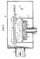
- Figure 3 shows a practical embodiment of a device which corresponds essentially to the variant of Figure 1, right part.
In Figur 1 ist eine Magnetronkatode 1 dargestellt, die - für sich genommen - zum Stande der Technik gehört. Einzelheiten der prinzipiellen Bauweise einer solchen Magnetronkatode sind außerdem Figur 3 zu entnehmen. Die Magnetronkatode 1 ist über eine Leitung 2 mit einer Gleichspannungsquelle 3 verbunden, die eine negative Gleichspannung zwischen etwa 400 und 1000 Volt abzugeben im Stande ist. Die Magnetronkatode 1 ist mit einem etwa kongruenten Target 4 aus einem elektrisch leitfähigen Material belegt, das die eine Komponente des zu bildenden Schichtmaterials liefert. Das Target besitzt eine Oberfläche 4a, die die sogenannte Zerstäubungsfläche ist.FIG. 1 shows a
Die Magnetronkatode bzw. das Target 4 ist im Randbereich von einer Verteileinrichtung 5 für das Reaktionsgas umgeben, wobei der Abstand kleinstmöglich gewählt ist, ohne daß jedoch die Verteileinrichtung 5 und die Targetoberfläche 4a in der Draufsicht gesehen einander überschneiden. Die nicht näher bezeichneten Austrittsöffnungen der Verteileinrichtung 5 sind nach unten gerichtet. Das Target 5 hat die Querabmessung "c". Bei einem kreisrunden Target 4 ist auch die Verteileinrichtung 5 als Ringleitung dargestellt, was hier der Übersichtlichkeit halber in der Zeichnung nicht festgehalten ist.The magnetron cathode or the target 4 is surrounded in the edge region by a
In planparalleler Ausrichtung zur Targetoberfläche 4a wird an der Magnetronkatode 1 ein Substrat 6 vorbeibewegt, das mit dem Reaktionsprodukt aus dem Targetmaterial und dem Reaktionsgas beschichtet werden soll. Der Abstand von der Targetoberfläche 4a zum Substrat 6 hat das Maß "a". Dieser Abstand liegt zwischen 40 und 60 mm, während die Querabmessung "c" des Targets nicht weiter kritisch ist und die üblichen Abmessungen aufweist. Innerhalb dieses Abstandes "a" liegt - in größerer Nähe zum Substrat 6 - eine Abschirmeinrichtung 7, deren Innenränder 7a einen Abstand "x" voneinander aufweisen, der zwischen dem 0,6-Fachen und dem 2,0-Fachen der Querabmessung "c" des Targets 4 liegt. Die Variabilität dieses Abstandes "x" wird durch die gestrichelten Verlängerungen der Abschirmeinrichtung 7 symbolisiert.A
Die Abschirmeinrichtung 7 ist isoliert angeordnet, was durch einen auf der linken Seite dargestellten Stützisolator 8 angedeutet ist. Sie ist weiterhin über eine Leitung 9 mit einer Gleichspannungsquelle 10 verbunden, die im Stande ist, eine Gleichspannung zwischen 0 und +200 Volt abzugeben. Die dem Target 4 zugekehrte Oberfläche 7b der Abschirmeinrichtung hat von dem Substrat 6 einen Abstand "d", der kleiner ist als die Hälfte des Abstandes "a". Beim Ausführungsbeispiel ist der Abstand "d" maximal der Summe der Dicke der Abschirmeinrichtung 7 und der Weite eines Spaltes 11 von etwa 5 mm.The
Im rechten Teil von Figur 1 (Teil A) ist eine Anordnung dargestellt, bei der die Magnetronkatode 1 einen relativ großen Abstand von einer seitlich daneben liegenden Wand 12 der Vakuumkammer hat. Der Abstand wird durch eine weitere Wand 13 der Vakuumkammer überbrückt, die insgesamt auf Massepotential liegt. Im vorliegenden Fall hat der Abstand der Kammerwand 12 von der Mittenachse der Katode 1 das Maß "b", und dieses beträgt b = 2 c. Bei dieser Anordnung belegen sich die Kammerwände 12 und 13 mit Schichten 14 und 15 aus mindestens teilweise isolierendem Material, wodurch die Kammerwände gegenüber dem Ausgangszustand allmählich ihre Anodenfunktion verlieren.The right part of FIG. 1 (part A) shows an arrangement in which the
Im linken Teil von Figur 1(Teil B) ist die Magentronkatode unter beengten Raumverhältnissen dargestellt, d.h. die Wand 16 der auf Massepotential liegenden Vakuumkammer ist sehr viel kürzer. Um hierbei eine Veränderung der Potentialverhältnisse mit fortschreitender Beschichtungsdauer zu verhindern, ist die unmittelbar angrenzende seitliche Wand 17 der Vakuumkammer isoliert aufgehängt, was durch einen Stützisolator 18 angedeutet ist. Dadurch kann die Wand 17 sich selbst auf ein frei gewähltes Zwischenpotential einstellen.In the left part of Figure 1 (part B) the magentron cathode is shown in a confined space, i.e. the
Die beiden Varianten nach Figur 1 eignen sich insbesondere für die Abscheidung von Schichten mit einer gewissen Restleitfähigkeit, wie z.B. von SiO₂. Dabei sind die als Anode wirkenden Teile entweder an Masse oder an positives Potential gegen Masse angeschlossen und im direkten Partikelstrom vor dem Substrat angeordnet. Auf den als Anode wirkenden Teilen kondensieren in diesem Falle Schichten, die für die Aufnahme des Entladungsstroms noch ausreichend leitfähig sind. Auf den anderen Flächen können sich ohne weiteres isolierende Schichten abscheiden. Wird mit Nullpotential an der als Anode wirkenden Abschirmeinrichtung 7 gearbeitet, so kann sie mit der Wand 12 kurzgeschlossen werden (Figur 2 , Teil A). In der Regel ist jedoch die als Anode wirkende Abschirmeinrichtung 7 von den umgebenden, als Plasmaschirm wirkenden Wänden getrennt angeordnet, z.B. dann, wenn diese Wände wie die Wand 17 "floaten" können, weil sie isoliert aufgehängt sind (Figur 1, Teil B).The two variants according to Figure 1 are particularly suitable for the deposition of layers with a certain residual conductivity, such as SiO₂. The parts acting as an anode are either at ground or connected to positive potential against ground and arranged in the direct particle stream in front of the substrate. In this case, layers condense on the parts acting as the anode, which are still sufficiently conductive to absorb the discharge current. Insulating layers can easily be deposited on the other surfaces. If work is carried out with zero potential on the
Die beiden Varianten A und B nach Figur 2 stimmen in Abmessungen und Anordnung im wesentlichen mit den entsprechenden Varianten A und B nach Figur 1 überein, so daß gleiche Bezugszeichen verwendet wurden. Wie bereits weiter oben ausgeführt wurde, sind die Varianten nach Figur 2 jedoch für die Herstellung isolierender Schichten vorgesehen. In diesem Falle kondensiert auch auf der Abschirmeinrichtung 7 eine isolierende Schicht 19, so daß diese - zumindest nach einiger Zeit - nicht mehr die Funktion einer Anode ausüben kann. Um hier eine Anodenfunktion sicher zu-stellen, ist in Zerstäubungsrichtung gesehen hinter der Abschirmeinrichtung 7 eine besondere Anode 20 angeordnet, die als wasserdurchströmtes Rohr ausgebildet ist. Die Anode 20 ist über eine Leitung 21 mit einer Gleichspannungsquelle 22 verbunden, durch die die Anode mit einer positiven Spannung zwischen etwa 40 und 120 Volt beaufschlagbar ist. Die Anode 20 ist dabei im Spalt 11 gegenüber den Kanten 7a soweit zurückgesetzt, daß sie nur noch in sehr geringem Umfange von isolierenden Partikeln getroffen werden kann. Die Abschirmeinrichtung 7 ist entweder zusammen mit den Wänden 12 und 13 an Massepotential gelegt (Figur 2, Teil A) oder auf einem selbstätig frei einstellbaren Potential durch einen Stützisolator 8 gehalten (Figur 2, Teil B). In jedem Falle hat die Abschirmeinrichtung 7 auch in Bezug auf die besondere Anode 20 eine Abschirmfunktion.The two variants A and B according to FIG. 2 correspond essentially in size and arrangement to the corresponding variants A and B according to FIG. 1, so that the same reference numerals have been used. As has already been explained above, the variants according to FIG. 2 are intended for the production of insulating layers. In this case, an insulating
Wie aus Figur 2 zu ersehen ist, sind die Anode 20 und die Abschirmeinrichtung 7 beide in großer Substratnähe angeordnet, und zwar in der Weise, daß der auf das Substrat 6 gelangende Anteil des Beschichtungsmaterials durch die Abschirmeinrichtung 7 praktisch nicht geändert wird. Die Potentialverhältnisse im gesamten Plasmaraum, insbesondere in der Substratnähe, bleiben zeitlich und räumlich stabil, wenn auf den genannten Oberflächen eine isolierende Schicht entsteht oder bereits vorhanden ist. Dabei müssen die genannten Teile jedoch elektrisch leitend sein, da sie sonst ihre Aufgaben im Bereich der Katode, störende Nebenentladungen zu unterdrücken, nicht erfüllen könnten.As can be seen from FIG. 2, the
Man kann zur Erzielung von Betriebsbedingungen, die von Anfang an stabil sind, auch so verfahren, daß man die genannten Oberflächen in einer Art Formierungsphase vor der eigentlichen Beschichtung der Substrate gezielt mit isolierenden Schichten versieht.To achieve operating conditions that are stable from the start, one can also proceed in such a way that the surfaces mentioned are deliberately provided with insulating layers in a kind of formation phase before the actual coating of the substrates.
Bei dem Ausführungsbeispiel nach Figur 3 ist schematisch auch eine Vakuumkammer 23 dargestellt, die in den Figuren 1 und 2 fortgelassen wurde. Diese Vakuumkammer ist über einen Saugstutzen 24 mit einem Satz nicht gezeigter Vakuumpumpen verbunden. Innerhalb der Vakuumkammer 23 ist ein Innengehäuse 25 angeordnet, das die Magnetronkatode 1 und die Verteileinrichtung 5 möglichst eng einschließt. Die Katode 1 mit ihrem Target 4 ist hier jedoch etwas mehr im Detail dargestellt, und zwar sind hier die Magnetpole N und S dargestellt, die über der Targetoberfläche 4a einen in sich geschlossenen Feldlinientunnel erzeugen, in dem das Plasma P eingeschlossen ist. Das Plasma folgt dabei dem Verlauf der Polflächen; bei einer kreisförmigen Magentronkatode hat es in etwa die Form eines Torus. Zur Magnetronkatode 1 gehört noch ein Katodengrundkörper 1a. Die Leitung 2 ist hier als Tragrohr ausgeführt und mittels eines Durchführungsisolators 26 durch die Wand der Vakuumkammer 23 hindurchgeführt. Die Seiteinflächen, die Rückseite und die Leitung 2 sind von einer gleichfalls auf Massepotential liegenden Dunkelraumabschirmung 27 umgeben.In the exemplary embodiment according to FIG. 3, a
Die Abschirmeinrichtung 7 ist hierbei Teil des Innengehäuses 25 und liegt mit diesem auf Massepotential. Zwischen den Innenrändern 7a wird in analoger Weise wie in den Figuren 1 und 2 eine Austrittsöffnung für das Beschichtungsmaterial gebildet, die die Abmessung "x" aufweist . Zwischen der Abschirmeinrichtung 7 und dem Substrat 6 wird jedoch auf dem Umfang des Innengehäuses 25 ein umlaufender Spalt 11 mit einer definierten Weite w und einer definierten Länge s gebildet. Hierdurch entsteht ein gewisser Drosseleffekt, der jedoch einen Gasaustausch durch Strömung und Diffusion ermöglicht. Durch die Verteileinrichtung 5 kann entweder reines Reaktionsgas oder Reaktionsgas im Gemisch mit einem Arbeitsgas (Argon) zugeführt werden. Außerhalb des Innengehäuses 25, aber innerhalb der Vakuumkammer 23 ist eine weitere Verteileinrichtung 28 angeordnet, durch die beispielhaft reines Arbeitsgas (Argon) zugeführt wird.The
Durch das Innengehäuse 25 wird (in Analogie zur Wand 17 in den Figuren 1 und 2) zwischen Target 4 und Substrat 6 eine Reaktionszone R abgegrenzt, und durch den Spalt 11 wird ein solcher Gleichgewichtszustand der Gasbewegungen erreicht, daß aus der Reaktionszone R weniger als 1/3, vorzugsweise weniger als 1/5 des unverbrauchten Reaktionsgases durch den Saugstutzen 24 abziehbar ist . Der Spalt 29 auf der Rückseite des Substrats 6 ist weniger kritisch. Er wird durch eine Platte 30 begrenzt, die jedoch für den Plasmaprozeß Bedeutung erlangt, wenn das Substrat 6 beispielsweise aus einer Folge von einzelnen plattenförmigen Substraten besteht, die mit Abstand durch die Reaktionszone R geführt werden.A reaction zone R is delimited between the target 4 and the
Durch die vorstehend beschriebenen Maßnahmen wird erreicht, daß das Reaktionsgas von der Verteileinrichtung 5 in der Nähe des Targets nahezu vollständig in den Bereich des dichten Plasmas vor der Targetoberfläche strömt und von dort zum Substrat diffundiert, wo es in der chemischen Reaktion zum aller-größten Teil verbraucht wird. Lediglich die genannte Restmenge wird durch den dort vorhandenen Spalt 11 abgesaugt. Auf diese Weise wird verhindert, daß angeregtes Reaktionsgas von den Vakuumpumpen unmittelbar abgesaugt und damit der Umsetzung in chemische Verbindungen am Substrat entzogen wird. Auf diese Weise wird die Dichte angeregter Reaktionsgasteilchen vor der Substratoberfläche erhöht. Dies hat wiederum zur Folge, daß das für die Einstellung des geforderten Reaktionsgrades notwendige Stosszahlverhältnis geringer wird.The measures described above ensure that the reaction gas flows almost completely from the
Wie in Figur 3 dargestellt, bestehen die Maßnahmen zur Ausbildung definierter Strömungsverhältnisse in der Wahl definierter Spaltbreiten und/oder Spaltlängen zwischen dem Substrat 6 und dem Innengehäuse 25 einerseits sowie in der Wahl einer effektiven Saugleistung der Vakuumpumpen am Saugstutzen 24.As shown in FIG. 3, the measures for forming defined flow conditions consist in the selection of defined gap widths and / or gap lengths between the
Hierbei sind zwei Fälle zu unterscheiden: Außer dem Reaktionsgas wird auch das Arbeitsgas (Argon) in das Innengehäuse 25 eingelassen, oder das Reaktionsgas wird allein in das genannte Gehäuse eingelassen. In dem zuerst genannten Fall muß die Flußrate, die durch die Abmessungen des Spaltes 11 bestimmt wird, als Summe der Flußraten von Reaktionsgas und Arbeitsgas bei gewähltem Totaldruck im Innengehäuse 25 dem effektiven Saugvermögen der Vakuumpumpe durch den Totaldruck in der Vakuumkammer 23 angepaßt werden. Im zweiten Fall wird das Arbeitsgas durch die Verteileinrichtung 28 in die Vakuumkammer 23 eingelassen und gelangt durch Diffusion in das Innengehäuse 25, in dem der reaktive Prozeß abläuft. Der Spalt 11 ist in diesem Falle im wesentlichen nur für den Reaktionsgasfluß zu dimensionieren, der abgesaugt werden soll. Beiden Fällen ist jedoch gemeinsam, daß die Partialdruckdifferenz zwischen dem Innengehäuse 25 und dem Raum in der Vakuumkammer 23 klein gehalten wird, um nur einen geringen Reaktionsgasfluß durch den Spalt 11 zu erzeugen.A distinction is made here between two cases: in addition to the reaction gas, the working gas (argon) is also let into the
In einer Vorrichtung nach Figur 3 wurde die effektive Saugleistung auf 100 l/s eingestellt. Die Magnetronkatode hatte eine Länge von 500 mm und wurde mit einer leistungsstabilisierten Stromversorgung mit einer Leistung von 1000 W versorgt. Der Gesamtdruck in der Vakuumkammer 23 betrug 4 × 10⁻³ mbar, und der Abstand "a" zwischen Targetoberfläche und Substrat betrug 40 mm. In diesem Falle wurde über die Verteileinrichtung 5 ein Fluß von 350 sccm an reinem Sauerstoff in das Innengehäuse 25 eingelassen und über die Verteileinrichtung 28 ein Fluß von 250 sccm Argon. Die auf beiden Seiten des Spaltes 11 erzielte Druckdifferenz betrug 1,7 × 10⁻³ mbar.In a device according to FIG. 3, the effective suction power was set to 100 l / s. The magnetron cathode had a length of 500 mm and was supplied with a power stabilized power supply with a power of 1000 W. The total pressure in the
Die Halte- und Führungseinrichtung für die Substrate ist in den Figuren 1 bis 3 nicht näher dargestellt. In Frage kommt hierfür beispielhaft ein um eine Achse rotierender, ansonsten aber ortsfest gelagerter Substrathalter, oder ein plattenförmiger oder rahmenförmiger Substrathalter, der auf Rollen oder Schienen innerhalb der Vakuumkammer verfahrbar ist. Speziell für die Herstellung von Isolatorschichten ist es notwendig, daß der Substrathalter sich auf einem selbsteinstellenden Potential befindet ("floatendes" Potential). Bei solchen Schichten würde ein auf Massepotential befindlicher Substrathalter die Potentialverhältnisse in der Katodenumgebung stark beeinflussen, da leitfähige Flächen in diesem Raum die Wirksamkeit der Anode beeinflussen und damit Schichtungleichmäßigkeiten und Bogenentladungen erzeugen könnten. Aber auch für elektrisch leitfähige Schichten ist das floatendes Potential des Substrathalters jedenfalls kein Nachteil.The holding and guiding device for the substrates is not shown in detail in FIGS. 1 to 3. For example, a substrate holder that rotates about an axis, but is otherwise mounted in a stationary manner, or a plate-shaped or frame-shaped substrate holder that can be moved on rollers or rails within the vacuum chamber. Especially for the production of insulator layers, it is necessary for the substrate holder to be at a self-adjusting potential ("floating" potential). In the case of such layers, a substrate holder located at ground potential would have a strong influence on the potential conditions in the vicinity of the cathode, since conductive surfaces in this space influence the effectiveness of the anode and could therefore produce layer unevenness and arc discharges. In any case, the floating potential of the substrate holder is also not a disadvantage for electrically conductive layers.
Claims (13)
Priority Applications (1)
| Application Number | Priority Date | Filing Date | Title |
|---|---|---|---|
| AT88103333T ATE81532T1 (en) | 1987-03-20 | 1988-03-04 | METHOD AND DEVICE FOR SPRAYING HIGH-RESISTANCE COATINGS BY CATODE SPRAYING. |
Applications Claiming Priority (2)
| Application Number | Priority Date | Filing Date | Title |
|---|---|---|---|
| DE19873709175 DE3709175A1 (en) | 1987-03-20 | 1987-03-20 | METHOD AND DEVICE FOR SPRAYING HIGH-OHMED LAYERS THROUGH CATODE SPRAYING |
| DE3709175 | 1987-03-20 |
Publications (3)
| Publication Number | Publication Date |
|---|---|
| EP0282836A2 true EP0282836A2 (en) | 1988-09-21 |
| EP0282836A3 EP0282836A3 (en) | 1989-07-26 |
| EP0282836B1 EP0282836B1 (en) | 1992-10-14 |
Family
ID=6323583
Family Applications (1)
| Application Number | Title | Priority Date | Filing Date |
|---|---|---|---|
| EP88103333A Expired - Lifetime EP0282836B1 (en) | 1987-03-20 | 1988-03-04 | Process and apparatus for depositing of high ohmic resistance layers by cathodic sputtering |
Country Status (5)
| Country | Link |
|---|---|
| US (1) | US4988422A (en) |
| EP (1) | EP0282836B1 (en) |
| JP (1) | JP2609273B2 (en) |
| AT (1) | ATE81532T1 (en) |
| DE (2) | DE3709175A1 (en) |
Cited By (1)
| Publication number | Priority date | Publication date | Assignee | Title |
|---|---|---|---|---|
| GB2211861B (en) * | 1987-10-30 | 1992-01-29 | Pioneer Electronic Corp | Photomagnetic memory medium having a non-columnar structure |
Families Citing this family (26)
| Publication number | Priority date | Publication date | Assignee | Title |
|---|---|---|---|---|
| US5281554A (en) * | 1991-02-08 | 1994-01-25 | Sharp Kabushiki Kaisha | Method for producing a semiconductor device having a tantalum thin film |
| DE4140862A1 (en) * | 1991-12-11 | 1993-06-17 | Leybold Ag | CATHODE SPRAYING SYSTEM |
| DE4223505C1 (en) * | 1992-07-17 | 1993-11-04 | Fraunhofer Ges Forschung | Reactive magnetron sputtering device for application of insulating or low conductivity layer - uses anode potential for relative isolation of all parts in contact with plasma on outside of cathode target |
| US5338422A (en) * | 1992-09-29 | 1994-08-16 | The Boc Group, Inc. | Device and method for depositing metal oxide films |
| US6605198B1 (en) * | 1993-07-22 | 2003-08-12 | Sputtered Films, Inc. | Apparatus for, and method of, depositing a film on a substrate |
| JPH07316810A (en) * | 1994-05-27 | 1995-12-05 | Fuji Xerox Co Ltd | Sputtering device |
| US5591313A (en) * | 1995-06-30 | 1997-01-07 | Tabco Technologies, Inc. | Apparatus and method for localized ion sputtering |
| JP3868020B2 (en) * | 1995-11-13 | 2007-01-17 | キヤノンアネルバ株式会社 | Long distance sputtering apparatus and long distance sputtering method |
| KR100391975B1 (en) * | 1996-08-06 | 2003-11-13 | 주식회사 코오롱 | Method for manufacturing high purity thin film |
| ES2184265T3 (en) * | 1997-04-14 | 2003-04-01 | Cemecon Ag | PVD COATING PROCEDURE AND DEVICE. |
| US5897753A (en) | 1997-05-28 | 1999-04-27 | Advanced Energy Industries, Inc. | Continuous deposition of insulating material using multiple anodes alternated between positive and negative voltages |
| US6818103B1 (en) | 1999-10-15 | 2004-11-16 | Advanced Energy Industries, Inc. | Method and apparatus for substrate biasing in multiple electrode sputtering systems |
| GB0222331D0 (en) * | 2002-09-26 | 2002-10-30 | Teer Coatings Ltd | A method for depositing multilayer coatings with controlled thickness |
| US20040250767A1 (en) * | 2003-04-21 | 2004-12-16 | Rohm And Haas Electronic Materials, L.L.C. | Method and apparatus for coating a substrate using combustion chemical vapor deposition |
| JP4493284B2 (en) * | 2003-05-26 | 2010-06-30 | キヤノンアネルバ株式会社 | Sputtering equipment |
| JP4521174B2 (en) * | 2003-10-15 | 2010-08-11 | 国立大学法人 名古屋工業大学 | Cluster manufacturing apparatus and cluster manufacturing method |
| ES2302401B2 (en) * | 2005-06-03 | 2009-03-16 | Universidad De Alicante | MICRO-TOPOGRAPHIC GENERATION SYSTEM BY CATHODIC SPRAYING. |
| DE102006028977B4 (en) * | 2006-06-23 | 2012-04-12 | Qimonda Ag | Sputterdepositions device |
| JP2008127615A (en) * | 2006-11-20 | 2008-06-05 | Fujitsu Ltd | Method for forming thin film, apparatus for forming thin film, and laminated film |
| JP4631940B2 (en) * | 2008-07-10 | 2011-02-16 | セイコーエプソン株式会社 | Sputtering apparatus and liquid crystal device manufacturing apparatus |
| KR101073557B1 (en) * | 2009-11-24 | 2011-10-14 | 삼성모바일디스플레이주식회사 | Sputtering Apparatus |
| US8821701B2 (en) | 2010-06-02 | 2014-09-02 | Clifton Higdon | Ion beam sputter target and method of manufacture |
| EP2549521A1 (en) * | 2011-07-21 | 2013-01-23 | Fraunhofer-Gesellschaft zur Förderung der angewandten Forschung e.V. | Method and device for producing low-particle layers on substrates |
| US8829769B1 (en) | 2012-11-09 | 2014-09-09 | Dantam K. Rao | Coated keybar to protect electric machines |
| JP2019178367A (en) * | 2018-03-30 | 2019-10-17 | 株式会社アルバック | Sputtering apparatus |
| US20200010948A1 (en) * | 2018-07-05 | 2020-01-09 | Beijing Apollo Ding Rong Solar Technology Co., Ltd. | Shielded sputter deposition apparatus and method |
Citations (3)
| Publication number | Priority date | Publication date | Assignee | Title |
|---|---|---|---|---|
| EP0047395A2 (en) * | 1980-09-10 | 1982-03-17 | International Business Machines Corporation | System for reactive ion etching |
| US4572842A (en) * | 1983-09-02 | 1986-02-25 | Leybold-Heraeus Gmbh | Method and apparatus for reactive vapor deposition of compounds of metal and semi-conductors |
| EP0205028A1 (en) * | 1985-06-12 | 1986-12-17 | Leybold Aktiengesellschaft | Apparatus for depositing thin layers on a substrate |
Family Cites Families (5)
| Publication number | Priority date | Publication date | Assignee | Title |
|---|---|---|---|---|
| FR2324755A1 (en) * | 1975-09-19 | 1977-04-15 | Anvar | HIGH SPEED OF DEPOSIT CATHODIC SPRAY DEVICE |
| DE2616270C3 (en) * | 1976-04-13 | 1981-01-15 | Siemens Ag, 1000 Berlin Und 8000 Muenchen | Method for producing a layer which is difficult to oxidize on a body made of an easily oxidizing metal or a corresponding metal alloy |
| US4278528A (en) * | 1979-10-09 | 1981-07-14 | Coulter Systems Corporation | Rectilinear sputtering apparatus and method |
| DE3112104A1 (en) * | 1981-03-27 | 1982-10-07 | Leybold-Heraeus GmbH, 5000 Köln | METHOD AND DEVICE FOR PRODUCING ELECTRICALLY CONDUCTIVE TRANSPARENT OXIDE LAYERS |
| CA1155798A (en) * | 1981-03-30 | 1983-10-25 | Shmuel Maniv | Reactive deposition method and apparatus |
-
1987
- 1987-03-20 DE DE19873709175 patent/DE3709175A1/en not_active Withdrawn
- 1987-06-08 US US07/059,067 patent/US4988422A/en not_active Expired - Fee Related
-
1988
- 1988-03-04 AT AT88103333T patent/ATE81532T1/en not_active IP Right Cessation
- 1988-03-04 EP EP88103333A patent/EP0282836B1/en not_active Expired - Lifetime
- 1988-03-04 DE DE8888103333T patent/DE3875263D1/en not_active Expired - Fee Related
- 1988-03-22 JP JP63065965A patent/JP2609273B2/en not_active Expired - Lifetime
Patent Citations (3)
| Publication number | Priority date | Publication date | Assignee | Title |
|---|---|---|---|---|
| EP0047395A2 (en) * | 1980-09-10 | 1982-03-17 | International Business Machines Corporation | System for reactive ion etching |
| US4572842A (en) * | 1983-09-02 | 1986-02-25 | Leybold-Heraeus Gmbh | Method and apparatus for reactive vapor deposition of compounds of metal and semi-conductors |
| EP0205028A1 (en) * | 1985-06-12 | 1986-12-17 | Leybold Aktiengesellschaft | Apparatus for depositing thin layers on a substrate |
Cited By (2)
| Publication number | Priority date | Publication date | Assignee | Title |
|---|---|---|---|---|
| GB2211861B (en) * | 1987-10-30 | 1992-01-29 | Pioneer Electronic Corp | Photomagnetic memory medium having a non-columnar structure |
| US5135819A (en) * | 1987-10-30 | 1992-08-04 | Pioneer Electronic Corporation | Photomagnetic memory medium having a non-columnar structure |
Also Published As
| Publication number | Publication date |
|---|---|
| EP0282836A3 (en) | 1989-07-26 |
| JPS64263A (en) | 1989-01-05 |
| JP2609273B2 (en) | 1997-05-14 |
| US4988422A (en) | 1991-01-29 |
| EP0282836B1 (en) | 1992-10-14 |
| ATE81532T1 (en) | 1992-10-15 |
| DE3875263D1 (en) | 1992-11-19 |
| DE3709175A1 (en) | 1988-09-29 |
Similar Documents
| Publication | Publication Date | Title |
|---|---|---|
| EP0282836B1 (en) | Process and apparatus for depositing of high ohmic resistance layers by cathodic sputtering | |
| EP0205028B1 (en) | Apparatus for depositing thin layers on a substrate | |
| DE3331707C2 (en) | ||
| EP0285745B1 (en) | Process and apparatus for vacuum coating by means of an electric arc discharge | |
| EP0235770B1 (en) | Device for the plasma processing of substrates in a high frequency excited plasma discharge | |
| EP0812368B1 (en) | Reactive sputtering process | |
| DE3726006C2 (en) | ||
| EP0508359B1 (en) | Process and apparatus for coating at least one object | |
| EP0489239B1 (en) | Sputtering apparatus with magnetron cathodes for coating of substrates | |
| EP0478909B1 (en) | Process and apparatus for obtaining a diamondlayer | |
| DE3150591C2 (en) | ||
| EP0282835B1 (en) | Process and device for controlling the reactive coating of substrates with layers, using magnetron cathodes | |
| EP0886880B1 (en) | Method and apparatus for the coating of workpieces | |
| DE4016352C2 (en) | ||
| DE4039930A1 (en) | Plasma treating appts. - has adjustable distance between edge of hollow electrode and substrate holding electrode to maintain constant radio frequency power | |
| DE3627151A1 (en) | METHOD AND DEVICE FOR REACTIVELY EVAPORATING METAL COMPOUNDS | |
| EP0803587A1 (en) | Method and apparatus for sputter coating | |
| DE2006075A1 (en) | Method and device for the production of fine powders of a metal or an alloy | |
| EP1759036A1 (en) | Coating device for coating a substrate and coating method | |
| DE1515300A1 (en) | Device for the production of high quality thin layers by cathode sputtering | |
| CH668565A5 (en) | METHOD AND ARRANGEMENT FOR SPRAYING A MATERIAL AT HIGH FREQUENCY. | |
| DE4328586A1 (en) | Controlling the reaction ratio during coating process - in which the partial pressure of the gas is adjusted by alteration of the evapn. rate of a solid reacting with the gas etc. | |
| DE2655942C2 (en) | ||
| DE102009008290A1 (en) | Coating a surface of substrate using reactive sputtering process in processing chamber, comprises supplying inert gas and reactive gas into the chamber, and operating double magnetron arranged opposite to substrate with alternating current | |
| DE2800852C2 (en) | Device for ion plasma coating |
Legal Events
| Date | Code | Title | Description |
|---|---|---|---|
| PUAI | Public reference made under article 153(3) epc to a published international application that has entered the european phase |
Free format text: ORIGINAL CODE: 0009012 |
|
| AK | Designated contracting states |
Kind code of ref document: A2 Designated state(s): AT BE CH DE FR GB IT LI NL |
|
| PUAL | Search report despatched |
Free format text: ORIGINAL CODE: 0009013 |
|
| AK | Designated contracting states |
Kind code of ref document: A3 Designated state(s): AT BE CH DE FR GB IT LI NL |
|
| 17P | Request for examination filed |
Effective date: 19890726 |
|
| 17Q | First examination report despatched |
Effective date: 19920327 |
|
| GRAA | (expected) grant |
Free format text: ORIGINAL CODE: 0009210 |
|
| AK | Designated contracting states |
Kind code of ref document: B1 Designated state(s): AT BE CH DE FR GB IT LI NL |
|
| PG25 | Lapsed in a contracting state [announced via postgrant information from national office to epo] |
Ref country code: IT Free format text: LAPSE BECAUSE OF FAILURE TO SUBMIT A TRANSLATION OF THE DESCRIPTION OR TO PAY THE FEE WITHIN THE PRE;WARNING: LAPSES OF ITALIAN PATENTS WITH EFFECTIVE DATE BEFORE 2007 MAY HAVE OCCURRED AT ANY TIME BEFORE 2007. THE CORRECT EFFECTIVE DATE MAY BE DIFFERENT FROM THE ONE RECORDED.SCRIBED TIME-LIMIT Effective date: 19921014 Ref country code: FR Effective date: 19921014 Ref country code: BE Effective date: 19921014 Ref country code: GB Effective date: 19921014 Ref country code: NL Effective date: 19921014 |
|
| REF | Corresponds to: |
Ref document number: 81532 Country of ref document: AT Date of ref document: 19921015 Kind code of ref document: T |
|
| REF | Corresponds to: |
Ref document number: 3875263 Country of ref document: DE Date of ref document: 19921119 |
|
| PG25 | Lapsed in a contracting state [announced via postgrant information from national office to epo] |
Ref country code: AT Effective date: 19930304 |
|
| EN | Fr: translation not filed | ||
| NLV1 | Nl: lapsed or annulled due to failure to fulfill the requirements of art. 29p and 29m of the patents act | ||
| PG25 | Lapsed in a contracting state [announced via postgrant information from national office to epo] |
Ref country code: LI Effective date: 19930331 Ref country code: CH Effective date: 19930331 |
|
| GBV | Gb: ep patent (uk) treated as always having been void in accordance with gb section 77(7)/1977 [no translation filed] |
Effective date: 19921014 |
|
| PLBE | No opposition filed within time limit |
Free format text: ORIGINAL CODE: 0009261 |
|
| STAA | Information on the status of an ep patent application or granted ep patent |
Free format text: STATUS: NO OPPOSITION FILED WITHIN TIME LIMIT |
|
| 26N | No opposition filed | ||
| REG | Reference to a national code |
Ref country code: CH Ref legal event code: PL |
|
| PGFP | Annual fee paid to national office [announced via postgrant information from national office to epo] |
Ref country code: DE Payment date: 19980225 Year of fee payment: 11 |
|
| PG25 | Lapsed in a contracting state [announced via postgrant information from national office to epo] |
Ref country code: DE Free format text: LAPSE BECAUSE OF NON-PAYMENT OF DUE FEES Effective date: 20000101 |