EP0282340B1 - Tape loading apparatus - Google Patents
Tape loading apparatus Download PDFInfo
- Publication number
- EP0282340B1 EP0282340B1 EP88302166A EP88302166A EP0282340B1 EP 0282340 B1 EP0282340 B1 EP 0282340B1 EP 88302166 A EP88302166 A EP 88302166A EP 88302166 A EP88302166 A EP 88302166A EP 0282340 B1 EP0282340 B1 EP 0282340B1
- Authority
- EP
- European Patent Office
- Prior art keywords
- tape
- take
- reel
- loading
- loading ring
- Prior art date
- Legal status (The legal status is an assumption and is not a legal conclusion. Google has not performed a legal analysis and makes no representation as to the accuracy of the status listed.)
- Expired - Lifetime
Links
Images
Classifications
-
- G—PHYSICS
- G11—INFORMATION STORAGE
- G11B—INFORMATION STORAGE BASED ON RELATIVE MOVEMENT BETWEEN RECORD CARRIER AND TRANSDUCER
- G11B15/00—Driving, starting or stopping record carriers of filamentary or web form; Driving both such record carriers and heads; Guiding such record carriers or containers therefor; Control thereof; Control of operating function
- G11B15/60—Guiding record carrier
- G11B15/66—Threading; Loading; Automatic self-loading
- G11B15/665—Threading; Loading; Automatic self-loading by extracting loop of record carrier from container
- G11B15/6653—Threading; Loading; Automatic self-loading by extracting loop of record carrier from container to pull the record carrier against drum
-
- G—PHYSICS
- G11—INFORMATION STORAGE
- G11B—INFORMATION STORAGE BASED ON RELATIVE MOVEMENT BETWEEN RECORD CARRIER AND TRANSDUCER
- G11B15/00—Driving, starting or stopping record carriers of filamentary or web form; Driving both such record carriers and heads; Guiding such record carriers or containers therefor; Control thereof; Control of operating function
- G11B15/18—Driving; Starting; Stopping; Arrangements for control or regulation thereof
- G11B15/43—Control or regulation of mechanical tension of record carrier, e.g. tape tension
Definitions
- the present invention relates to a tape loading apparatus for use with a rotary magnetic head type recording and/or reproducing apparatus such as a video tape recorder.
- VTR video tape recorder
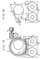
- a tape cassette 1 When a tape cassette 1 is loaded into a VTR (not shown), as shown in fig 1A, loading guides 3, 4 and 5 mounted on a loading ring 2 are brought into the tape withdrawing position. Then, a motor 6 drives a worm gear 7 to rotate the loading ring 2 in the direction shown by arrow L to withdraw the tape 8 from the tape cassette 1. The withdrawn tape 8 is then wrapped around a rotary drum 9 by a predetermined rotational angle, in this case, 180° as shown in fig 1B and the loading operation is complete.
- reference numeral 10 designates a pinch roller and 11 a capstan of the tape transport mechanism.
- a braking force is applied to the tape supply reel 12 in the tape cassette 1 and a constant torque is applied to the take-up reel 13 in the direction resisting the tape supply.
- the loading ring 2 is rotated at a predetermined speed to withdraw the tape 8 from the take-up reel 13.
- the first to third guides 3 to 5 are sequentially operated to bring the withdrawn tape 8 at the predetermined loading position shown in fig 1B.
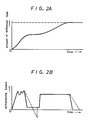
- the speed of withdrawal of tape from the tape cassette 1 is as shown by the solid line in fig 2B, while the volume of the tape 8 withdrawn from the tape cassette 1 changes as shown by a solid line in fig 2A.
- the rotational speed of the loading ring 2 is constant so that the inclination of the change of the tape withdrawing speed is steep.
- a magnetic tape cassette recording and/or reproducing device including a cylindrical tape guide drum having at least one rotary head associated therewith for recording and/or reproducing signals on a magnetic tape wrapped around the drum, a cassette holder spaced from said drum for operatively positioning a tape cassette containing supply and take-up reels on which said magnetic tape is wound, and a tape loading apparatus operative in a loading operation to withdraw said magnetic tape from the operatively positioned tape cassette and to wrap the withdrawn tape about said drum: the combination of
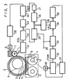
- Fig 3 is a block diagram showing the embodiment of the present invention.
- like parts corresponding to those of figs 1A and 1B are marked with the same references and therefore need not be described in detail.
- a reel drive motor for the supply reel 12 is used to apply to it a braking force to prevent the supply reel 12 from rotating similarly as described above,
- the rotational speed of the loading ring 2 is not constant but is controlled to change in response to the loading position.
- the torque applied to the take-up reel 13 in the direction opposite to the tape withdrawing direction is selected in accordance with the radius of the tape 8 wrapped on the take-up reel 13 to compensate for the effect that that radius has on the inertia of the reel 13.
- the tape 8 can be protected from being damaged more effectively.
- a frequency generator 21 is coaxially provided on a worm wheel 7a of the worm gear 7 which rotates the loading ring 2. Since the rotational speed of the worm wheel 7a is in proportion to the rotational speed of the loading ring 2, the frequency generator 21 generates a frequency signal FGL corresponding to the rotational speed of the loading ring 2.
- This frequency signal FGL is supplied through a waveform shaping circuit 22 to a frequency-to-voltage converting circuit 23 which then generates a voltage corresponding to the frequency of the signal FGL. This voltage is supplied to a comparing circuit 24.
- the comparing circuit 24 compares this voltage with a reference voltage REF, which will be described later, to produce a difference voltage therebetween.
- the difference voltage therefrom is supplied to a motor drive circuit 28 which controls the rotational speed of the motor 6.
- the loading ring 2 is controlled to rotate at a rotational speed corresponding to the reference voltage REF.
- the rotational speed of the loading ring 2 is controlled by changing the reference voltage REF supplied to the comparing circuit 24 in response to the volume of tape 8 withdrawn from the tape cassette 1, that is, the loading position.
- the frequency signal FGL through the waveform shaping circuit 22 is supplied to a clock terminal of a counter 25.
- the counter 25 is reset by a reset signal applied thereto from a terminal 29 before the loading operation begins, and it counts up "0", “1", “2”, ... as the loading ring 2 rotates.
- the count output from the counter 25 is supplied as an address signal to a ROM (read-only memory) 26 which functions as a look-up table.
- the count value of the counter 25 corresponds to the amount through which the loading ring 2 rotates. This amount corresponds to the loading position.
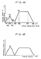
- the ROM 26 stores the digital values of the reference voltage REF needed at respective loading positions to change the rotational speed of the loading ring 2 in response to the loading positions as shown in fig 4A.
- the ROM 26 sequentially stores the digital values of the reference voltage REF which changes rectilinearly in response to the position of every pulse or wave of the frequency signal FGL such that the rotational speed of the loading ring 2 is changed rectilinearly up to the loading position of the count value N1 or up to a speed V1 from the beginning of rotation of the loading ring 2.
- the digital value of the reference voltage REF is sequentially read from the ROM 26, converted into a voltage by a D/A (digital to analog) converter 27 and then fed to the comparing circuit 24 as the reference voltage REF.
- the loading ring 2 rotates with different rotating speeds as shown in fig 4A and the tape 8 is withdrawn from the tape cassette 1 at speeds changing with a gentle inclination as represented by the curve in fig 4B, thus preventing the tape 8 from being damaged.
- a drive motor 30 is provided to rotate the take-up reel 13, and a frequency generator 31 is provided to generate a frequency signal FGW corresponding to the revolution speed of the drive motor 30.
- the frequency generator 31 supplies the frequency signal FGW through a waveform shaping circuit 32 to a clock terminal of a counter 33. Before the loading operation begins, this counter 33 is reset by the reset signal applied from the terminal 29, similarly to the counter 25.
- the frequency generator 31 generates the frequency signal FGW corresponding to the rotating amount of the take-up reel 13 to permit the counter 33 to count up "0", "1", "2", .... Therefore, the count value of the counter 33 is equal to the angle through which the take-up reel 13 has rotated from a starting point of the loading operation.
- the count output from the counter 33 is supplied to a latch circuit 34. Meanwhile, the count output from the counter 25 which counts the signal FGL is supplied to a decoder 35. When the counter 25 counts a predetermined value N, the decoder 35 produces a pulse LA. This pulse LA is supplied to the latch circuit 34 as a latch pulse by which the count value of the counter 33 at that time is latched in the latch circuit 34.
- the count value detected by the decoder 35 is made a value when the tape withdrawn amount is changing rectilinearly from the loading starting point.
- the count value is selected to be smaller than N1.
- the count value of the counter 25 is in proportion to the amount in which the tape 8 is withdrawn from the tape cassette 1. Therefore, the latch circuit 34 latches the number of pulses or waves of the signal FGW corresponding to the angle in which the take-up reel 13 rotates until the tape 8 is withdrawn from the tape cassette 1 by a predetermined length l represented by the count value N.
- the output from the latch circuit 34 is supplied to a calculating circuit 36.
- the calculating circuit 36 calculates the radius of the tape 8 wrapped on the take-up reel 13 from the known length l and the rotating angle of the take-up reel 13, ie, the output from the latch circuit 34.
- the thus obtained output indicating the radius of the tape 8 wrapped on the take-up reel 13 is supplied to a torque applying circuit 37 which applies a torque signal corresponding to the above radius to the drive motor 30 to bias the take-up reel 13 in the direction indicated by an arrow R in fig 3.
- the calculating circuit 36 may be formed of a microcomputer for calculating the radius of the tape 8 wrapped on the take-up reel 13.
- the following version is possible. Since the length l of the withdrawn tape 8 is constant and is already known, data indicating the radius corresponding to the count value latched in the latch circuit 34 is stored in a ROM and the output from the latch circuit 34 is supplied to this ROM as an address. In this case, data indicating the radius of the tape 8 wrapped on the take-up reel 13 rectilinearly corresponding to the count value is not stored in the ROM but data indicative of one approximate radius for every predetermined range of the count value is stored in the ROM.
- the torque applied to the take-up reel 13 is changed in response to the radius of the tape 8 wrapped on the take-up reel 13.
- the amount in which the tape 8 is damaged can be considerably reduced as compared with the prior art.
- the loading ring 2 can rotate at optimum rotating speed obtained via various experiments and simulations. It is needless to say that the thus obtained optimum rotating speed data may be stored in the ROM 26.
- the rotating speed of the loading ring is changed in accordance with the loading position, the speed at which the tape is withdrawn from the tape cassette can be prevented from changing sharply. Therefore, under the condition that the constant torque is applied to the take-up reel, even if the tape cassette is large-sized and the inertia of the take-up reel becomes large, the tape can be prevented from being placed in its slackened or tense state. Thus, the tape can be protected from being damaged.
Landscapes
- Indexing, Searching, Synchronizing, And The Amount Of Synchronization Travel Of Record Carriers (AREA)
- Basic Packing Technique (AREA)
- Manufacturing Of Electric Cables (AREA)
- Unwinding Webs (AREA)
Abstract
Description
- The present invention relates to a tape loading apparatus for use with a rotary magnetic head type recording and/or reproducing apparatus such as a video tape recorder.
- In a video tape recorder (VTR) employing a tape cassette, the tape loading operation in which a tape is withdrawn from a tape cassette and is then wrapped around a rotary head drum is conventionally carried out as shown in figs 1A and 1B of the accompanying drawings.
- When a tape cassette 1 is loaded into a VTR (not shown), as shown in fig 1A,
loading guides 3, 4 and 5 mounted on a loading ring 2 are brought into the tape withdrawing position. Then, a motor 6 drives aworm gear 7 to rotate the loading ring 2 in the direction shown by arrow L to withdraw thetape 8 from the tape cassette 1. The withdrawntape 8 is then wrapped around arotary drum 9 by a predetermined rotational angle, in this case, 180° as shown in fig 1B and the loading operation is complete. In fig 1B, reference numeral 10 designates a pinch roller and 11 a capstan of the tape transport mechanism. - Upon loading, a braking force is applied to the
tape supply reel 12 in the tape cassette 1 and a constant torque is applied to the take-up reel 13 in the direction resisting the tape supply. In this state, the loading ring 2 is rotated at a predetermined speed to withdraw thetape 8 from the take-up reel 13. Then, the first to third guides 3 to 5 are sequentially operated to bring the withdrawntape 8 at the predetermined loading position shown in fig 1B. - Due to the movement of the
loading guides 3, 4 and 5 during the tape loading operation and the sudden stopping of thetape 8 at the completion of the loading operation or the like, the speed of withdrawal of tape from the tape cassette 1 is as shown by the solid line in fig 2B, while the volume of thetape 8 withdrawn from the tape cassette 1 changes as shown by a solid line in fig 2A. - In the prior art, the rotational speed of the loading ring 2 is constant so that the inclination of the change of the tape withdrawing speed is steep.
- When the tape cassette 1 is large, the inertia of the take-
up reel 13 cannot be neglected. Thus, when the torque applied to the take-up reel 13 is constant, the following problems are encountered. - When the withdrawing speed of the
tape 8 is decreased as shown by the solid line in fig 2B, if the change in the rotational speed of the take-up reel 13 determined by the inertia of the take-up reel 13 and the torque applied thereto and the change in the tape withdrawing speed are similar, the tape tension is always constant and hence there is no problem. However, the inertia of the take-up reel 13 increases with the increase of the radius of the volume of thetape 8 wrapped on the take-up reel 13. Since the torque applied to the take-up reel 13 is constant, the rate of change of the rotational speed of the take-up reel 13 changes. When the radius of the volume of thetape 8 wrapped on the take-up reel 13 is large, and hence the inertia of the take-up reel 13 is large, as shown by the broken line in fig 2B, the rotational speed of the take-up reel 13 changes with a gentle inclination relative to the rapid change of the tape withdrawing speed, thus causing the withdrawntape 8 to be slackened. The amount of slackening of the withdrawntape 8 increases with the radius of thetape 8 wrapped on the take-up reel 13. In worst cases, thetape 8 may slip off from the loading guide. Further, since the tension is suddenly applied to the slackenedtape 8, thetape 8 may be damaged. This risk occurs also when the loading ring 2 is stopped at the completion of the loading operation. - Accordingly, it is an object of the present invention to provide an improved tape loading apparatus which avoids the foregoing problems of the prior art.
- According to the present invention, there is provided a magnetic tape cassette recording and/or reproducing device including a cylindrical tape guide drum having at least one rotary head associated therewith for recording and/or reproducing signals on a magnetic tape wrapped around the drum, a cassette holder spaced from said drum for operatively positioning a tape cassette containing supply and take-up reels on which said magnetic tape is wound, and a tape loading apparatus operative in a loading operation to withdraw said magnetic tape from the operatively positioned tape cassette and to wrap the withdrawn tape about said drum: the combination of
- a) a supply reel motor and a take-up reel motor for applying torques resisting rotations of said supply reel and take-up reel, respectively, of the operatively positioned tape cassette in directions for unwinding the tape therefrom;
- b) loading ring means having guide means positioned thereon for withdrawing the tape when said loading ring means is rotated in a loading operation; and
- c) loading ring driving means for rotatably driving said loading ring means; characterised by
- d) rotation detecting means for detecting the rotation of said loading ring means and generating a detected signal indicating the rotating position of said loading ring means; and
- e) control means for controlling said loading ring driving means according to said detected signal such that the speed at which the tape is withdrawn from the tape cassette can be prevented from changing sharply.
- The following detailed description of the illustrative embodiment of the present invention should be taken in conjunction with the accompanying drawings, throughout which like reference numerals identify the same or similar parts. In the drawings:-
- Figs 1A and 1B are diagrams used to explain the loading operation of the tape;
- Figs 2A and 2B are respectively diagrams used to explain the prior art;
- Fig 3 is a block diagram showing an embodiment of a tape loading apparatus according to the present invention; and
- Figs 4A and 4B are diagrams used to explain the operation of the present invention.
- An embodiment of a tape loading apparatus according to the present invention will hereinafter be described with reference to the drawings. Fig 3 is a block diagram showing the embodiment of the present invention. In fig 3, like parts corresponding to those of figs 1A and 1B are marked with the same references and therefore need not be described in detail.
- As illustrated in fig 3, in accordance with this embodiment, upon loading, a reel drive motor (not shown) for the
supply reel 12 is used to apply to it a braking force to prevent thesupply reel 12 from rotating similarly as described above, In this invention, however, the rotational speed of the loading ring 2 is not constant but is controlled to change in response to the loading position. Also, the torque applied to the take-up reel 13 in the direction opposite to the tape withdrawing direction is selected in accordance with the radius of thetape 8 wrapped on the take-up reel 13 to compensate for the effect that that radius has on the inertia of thereel 13. Thus, thetape 8 can be protected from being damaged more effectively. - According to this embodiment, a frequency generator 21 is coaxially provided on a worm wheel 7a of the
worm gear 7 which rotates the loading ring 2. Since the rotational speed of the worm wheel 7a is in proportion to the rotational speed of the loading ring 2, the frequency generator 21 generates a frequency signal FGL corresponding to the rotational speed of the loading ring 2. - This frequency signal FGL is supplied through a
waveform shaping circuit 22 to a frequency-to-voltage converting circuit 23 which then generates a voltage corresponding to the frequency of the signal FGL. This voltage is supplied to a comparing circuit 24. - The comparing circuit 24 compares this voltage with a reference voltage REF, which will be described later, to produce a difference voltage therebetween. The difference voltage therefrom is supplied to a
motor drive circuit 28 which controls the rotational speed of the motor 6. Thus, the loading ring 2 is controlled to rotate at a rotational speed corresponding to the reference voltage REF. - In this case, the rotational speed of the loading ring 2 is controlled by changing the reference voltage REF supplied to the comparing circuit 24 in response to the volume of
tape 8 withdrawn from the tape cassette 1, that is, the loading position. - Specifically, the frequency signal FGL through the
waveform shaping circuit 22 is supplied to a clock terminal of acounter 25. Thecounter 25 is reset by a reset signal applied thereto from aterminal 29 before the loading operation begins, and it counts up "0", "1", "2", ... as the loading ring 2 rotates. The count output from thecounter 25 is supplied as an address signal to a ROM (read-only memory) 26 which functions as a look-up table. - The count value of the
counter 25 corresponds to the amount through which the loading ring 2 rotates. This amount corresponds to the loading position. TheROM 26 stores the digital values of the reference voltage REF needed at respective loading positions to change the rotational speed of the loading ring 2 in response to the loading positions as shown in fig 4A. In fig 4A, N1, N2 ... N8 depict and denote count values and, for example, N8 = 500. Thus, theROM 26 sequentially stores the digital values of the reference voltage REF which changes rectilinearly in response to the position of every pulse or wave of the frequency signal FGL such that the rotational speed of the loading ring 2 is changed rectilinearly up to the loading position of the count value N1 or up to a speed V1 from the beginning of rotation of the loading ring 2. - As the count value of the
counter 25 changes with the rotation of the loading ring 2, the digital value of the reference voltage REF, which is sequentially changed, is sequentially read from theROM 26, converted into a voltage by a D/A (digital to analog)converter 27 and then fed to the comparing circuit 24 as the reference voltage REF. - Therefore, the loading ring 2 rotates with different rotating speeds as shown in fig 4A and the
tape 8 is withdrawn from the tape cassette 1 at speeds changing with a gentle inclination as represented by the curve in fig 4B, thus preventing thetape 8 from being damaged. - As earlier noted, according to the present invention, by changing the torque applied to the tape-
up reel 13 in accordance with the radius of thetape 8 wrapped on the take-up reel 13, it becomes possible to more effectively protect thetape 8 from being damaged. - To be concrete, as illustrated in fig 3, a drive motor 30 is provided to rotate the take-
up reel 13, and afrequency generator 31 is provided to generate a frequency signal FGW corresponding to the revolution speed of the drive motor 30. Thefrequency generator 31 supplies the frequency signal FGW through awaveform shaping circuit 32 to a clock terminal of acounter 33. Before the loading operation begins, thiscounter 33 is reset by the reset signal applied from theterminal 29, similarly to thecounter 25. Thus, when the loading operation begins and thetape 8 is withdrawn from the take-up reel 13 and the take-up reel 13 is rotated, thefrequency generator 31 generates the frequency signal FGW corresponding to the rotating amount of the take-up reel 13 to permit thecounter 33 to count up "0", "1", "2", .... Therefore, the count value of thecounter 33 is equal to the angle through which the take-up reel 13 has rotated from a starting point of the loading operation. - The count output from the
counter 33 is supplied to a latch circuit 34. Meanwhile, the count output from thecounter 25 which counts the signal FGL is supplied to adecoder 35. When the counter 25 counts a predetermined value N, thedecoder 35 produces a pulse LA. This pulse LA is supplied to the latch circuit 34 as a latch pulse by which the count value of thecounter 33 at that time is latched in the latch circuit 34. - In this case, the count value detected by the
decoder 35 is made a value when the tape withdrawn amount is changing rectilinearly from the loading starting point. In the illustrated example, as will be clear from the curve in fig 4A, the count value is selected to be smaller than N1. Within this range, the count value of thecounter 25 is in proportion to the amount in which thetape 8 is withdrawn from the tape cassette 1. Therefore, the latch circuit 34 latches the number of pulses or waves of the signal FGW corresponding to the angle in which the take-up reel 13 rotates until thetape 8 is withdrawn from the tape cassette 1 by a predetermined length ℓ represented by the count value N. The output from the latch circuit 34 is supplied to a calculatingcircuit 36. The calculatingcircuit 36 calculates the radius of thetape 8 wrapped on the take-up reel 13 from the known length ℓ and the rotating angle of the take-up reel 13, ie, the output from the latch circuit 34. The thus obtained output indicating the radius of thetape 8 wrapped on the take-up reel 13 is supplied to atorque applying circuit 37 which applies a torque signal corresponding to the above radius to the drive motor 30 to bias the take-up reel 13 in the direction indicated by an arrow R in fig 3. - In practice, the calculating
circuit 36 may be formed of a microcomputer for calculating the radius of thetape 8 wrapped on the take-up reel 13. The following version is possible. Since the length ℓ of the withdrawntape 8 is constant and is already known, data indicating the radius corresponding to the count value latched in the latch circuit 34 is stored in a ROM and the output from the latch circuit 34 is supplied to this ROM as an address. In this case, data indicating the radius of thetape 8 wrapped on the take-up reel 13 rectilinearly corresponding to the count value is not stored in the ROM but data indicative of one approximate radius for every predetermined range of the count value is stored in the ROM. - According to this embodiment, the torque applied to the take-
up reel 13 is changed in response to the radius of thetape 8 wrapped on the take-up reel 13. However, even if the constant torque is applied to the take-up reel 13 as in the prior art, the amount in which thetape 8 is damaged can be considerably reduced as compared with the prior art. - During the loading operation, the loading ring 2 can rotate at optimum rotating speed obtained via various experiments and simulations. It is needless to say that the thus obtained optimum rotating speed data may be stored in the
ROM 26. - According to the present invention, as set forth above, since the rotating speed of the loading ring is changed in accordance with the loading position, the speed at which the tape is withdrawn from the tape cassette can be prevented from changing sharply. Therefore, under the condition that the constant torque is applied to the take-up reel, even if the tape cassette is large-sized and the inertia of the take-up reel becomes large, the tape can be prevented from being placed in its slackened or tense state. Thus, the tape can be protected from being damaged.
Claims (8)
- In a magnetic tape cassette recording and/or reproducing device including a cylindrical tape guide drum (9) having at least one rotary head associated therewith for recording and/or reproducing signals on a magnetic tape (8) wrapped around the drum (9), a cassette holder spaced from said drum for operatively positioning a tape cassette (1) containing supply (12) and take-up (13) reels on which said magnetic tape (8) is wound, and a tape loading apparatus (2-9) operative in a loading operation to withdraw said magnetic tape (8) from the operatively positioned tape cassette (1) and to wrap the withdrawn tape (8) about said drum: the combination ofa) a supply reel motor and a take-up reel motor (30) for applying torques resisting rotations of said supply reel (12) and take-up reel (13), respectively, of the operatively positioned tape cassette (1) in directions for unwinding the tape therefrom;b) loading ring means (2) having guide means (3-5) positioned thereon for withdrawing the tape (8) when said loading ring means (2) is rotated in a loading operation; andc) loading ring driving means (6, 7, 7a) for rotatably driving said loading ring means (2); characterised byd) rotation detecting means (21, 22, 25) for detecting the rotation of said loading ring means (2) and generating a detected signal indicating the rotating position of said loading ring means (2); ande) control means (23, 24, 28) for controlling said loading ring driving means (2) according to said detected signal such that the speed at which the tape is withdrawn from the tape cassette can be prevented from changing sharply.
- A device according to claim 1, wherein said loading ring driving means includes a motor (6) and gear means (7, 7a) for transmitting the rotation of said motor (6) to said loading ring means (2).
- A device according to claim 2, wherein said rotation detecting means includes a frequency generator (21) for generating an output signal as said loading ring means (2) is rotated.
- A device according to claim 3, wherein said control means includes a comparator (24) for comparing the output of said frequency generator (21) and a reference value (REF) generated by a reference signal generator (26, 27) and generating a control signal supplied to said motor (6).
- A device according to claim 4, wherein said reference signal generator includes counter means (25) for counting the output signal of said frequency generator (21), read-only-memory means (26) for storing a plurality of reference values at a plurality of addresses and the output of said counter means (25) is arranged to be supplied to said read-only-memory means (26) as an address signal, and a D/A (digital to analog) converter (27) for converting the output signal of said read-only memory means (26) to an analog signal.
- A device according to any one of the preceding claims, further comprising take-up reel motor control means (31-37) for controlling the torque applied to said take-up reel.
- A device according to claim 6, wherein said take-up reel motor control means includes detecting (31-36) means for detecting the radius of the tape wound on one of said supply and take-up reels of the operatively positioned tape cassette and torque control means (37) for determining the torque applied to said take-up reel.
- A device according to claim 7, wherein said detecting means includes a second frequency generator (31) for detecting the rotation of said take-up reel, second counter means (33) for counting the output of said second frequency generator, latch means (34) controlled by a latch signal generated by the output signal of said rotation detecting means and latching the output of said second counter means (33), and calculating means (36) for calculating the radius of the tape cased on the output of said latch means (34).
Priority Applications (1)
| Application Number | Priority Date | Filing Date | Title |
|---|---|---|---|
| AT88302166T ATE82427T1 (en) | 1987-03-13 | 1988-03-11 | TAPE CHARGER. |
Applications Claiming Priority (2)
| Application Number | Priority Date | Filing Date | Title |
|---|---|---|---|
| JP62058213A JPS63224063A (en) | 1987-03-13 | 1987-03-13 | Tape loading device |
| JP58213/87 | 1987-03-13 |
Publications (3)
| Publication Number | Publication Date |
|---|---|
| EP0282340A2 EP0282340A2 (en) | 1988-09-14 |
| EP0282340A3 EP0282340A3 (en) | 1990-01-17 |
| EP0282340B1 true EP0282340B1 (en) | 1992-11-11 |
Family
ID=13077773
Family Applications (1)
| Application Number | Title | Priority Date | Filing Date |
|---|---|---|---|
| EP88302166A Expired - Lifetime EP0282340B1 (en) | 1987-03-13 | 1988-03-11 | Tape loading apparatus |
Country Status (7)
| Country | Link |
|---|---|
| US (1) | US4868923A (en) |
| EP (1) | EP0282340B1 (en) |
| JP (1) | JPS63224063A (en) |
| KR (1) | KR970002839B1 (en) |
| AT (1) | ATE82427T1 (en) |
| CA (1) | CA1329259C (en) |
| DE (1) | DE3875759T2 (en) |
Families Citing this family (11)
| Publication number | Priority date | Publication date | Assignee | Title |
|---|---|---|---|---|
| JPH02265069A (en) * | 1989-04-04 | 1990-10-29 | Matsushita Electric Ind Co Ltd | Tape driver |
| JPH02308462A (en) * | 1989-05-23 | 1990-12-21 | Victor Co Of Japan Ltd | Cassette discriminator |
| US5463299A (en) * | 1989-06-07 | 1995-10-31 | Hitachi, Ltd. | Current controller for controlling a current flowing in a load using a PWM inverter and method used thereby |
| JP2846043B2 (en) * | 1990-03-14 | 1999-01-13 | 株式会社日立製作所 | Cassette tape loading device |
| US5307215A (en) * | 1990-04-13 | 1994-04-26 | Hitachi, Ltd. | Method and device for loading tape in magnetic recorder |
| JPH04139645A (en) * | 1990-09-29 | 1992-05-13 | Toshiba Corp | Reel driver for magnetic recording and reproducing device |
| JPH04356755A (en) * | 1991-06-03 | 1992-12-10 | Hitachi Ltd | Tape loading device in magnetic recording and reproducing device |
| AT396853B (en) * | 1991-08-16 | 1993-12-27 | Philips Nv | DEVICE AT LEARNED TO PLAY PLAYBACK SIGNALS FROM A MAGNETIC TAPE |
| US5699205A (en) * | 1993-06-25 | 1997-12-16 | Matsushita Electric Industrial Co., Ltd. | Tape loading apparatus |
| US5836533A (en) * | 1996-10-31 | 1998-11-17 | Ampex Corporation | Hybrid arm-position/tape-tension servocontrol system |
| US6157512A (en) * | 1997-09-09 | 2000-12-05 | Canon Kabushiki Kaisha | Recording and/or reproducing apparatus including tape loading mechanism with speed control of tape loading guides |
Family Cites Families (6)
| Publication number | Priority date | Publication date | Assignee | Title |
|---|---|---|---|---|
| US4401923A (en) * | 1980-10-30 | 1983-08-30 | Ampex Corporation | Digital open loop tape tension control circuit for tape recorders and the like |
| US4398227A (en) * | 1981-03-16 | 1983-08-09 | Storage Technology Corporation | Magnetic tape drive with adaptive servo |
| JPS5982661A (en) * | 1982-11-01 | 1984-05-12 | Victor Co Of Japan Ltd | Magnetic recording and reproducing device |
| US4686591A (en) * | 1983-12-27 | 1987-08-11 | Canon Kabushiki Kaisha | Tape loading device for a recording and/or reproducing apparatus |
| US4628375A (en) * | 1985-06-28 | 1986-12-09 | Transamerica Delaval Inc. | Control systems for magnetic recording tapes |
| JPH0785320B2 (en) * | 1986-04-03 | 1995-09-13 | ソニー株式会社 | Tape drawer |
-
1987
- 1987-03-13 JP JP62058213A patent/JPS63224063A/en active Pending
-
1988
- 1988-02-25 US US07/160,482 patent/US4868923A/en not_active Expired - Lifetime
- 1988-02-26 CA CA000559910A patent/CA1329259C/en not_active Expired - Fee Related
- 1988-03-11 AT AT88302166T patent/ATE82427T1/en not_active IP Right Cessation
- 1988-03-11 EP EP88302166A patent/EP0282340B1/en not_active Expired - Lifetime
- 1988-03-11 DE DE8888302166T patent/DE3875759T2/en not_active Expired - Fee Related
- 1988-03-12 KR KR1019880002178A patent/KR970002839B1/en not_active IP Right Cessation
Also Published As
| Publication number | Publication date |
|---|---|
| EP0282340A2 (en) | 1988-09-14 |
| KR880011767A (en) | 1988-10-31 |
| US4868923A (en) | 1989-09-19 |
| DE3875759D1 (en) | 1992-12-17 |
| JPS63224063A (en) | 1988-09-19 |
| ATE82427T1 (en) | 1992-11-15 |
| KR970002839B1 (en) | 1997-03-12 |
| EP0282340A3 (en) | 1990-01-17 |
| CA1329259C (en) | 1994-05-03 |
| DE3875759T2 (en) | 1993-04-01 |
Similar Documents
| Publication | Publication Date | Title |
|---|---|---|
| EP0282340B1 (en) | Tape loading apparatus | |
| US4688115A (en) | Apparatus for reproducing a digital signal | |
| US4213583A (en) | Reel drive motor control system for cassette/cartridge tape recorders | |
| US4389600A (en) | Tape media interlayer tension check | |
| AU595867B2 (en) | Tape loading apparatus | |
| US5701214A (en) | Tape loading device in magnetic recording/playback apparatus that controls loading based on calculated reel inertia and tape position | |
| EP0376960A4 (en) | Apparatus for providing a profiled tape tension without utilizing a tape pack diameter sensor | |
| EP0176326B1 (en) | Adaptive end of tape detection apparatus and method | |
| US4381089A (en) | Wound-tape radius detection system for a tape recorder | |
| US5757570A (en) | Reel servo device for recording/reproducing apparatus employing a tape as recording medium | |
| US4631605A (en) | Multiple speed scanner servo system for protecting the heads and tape of helical recorders | |
| EP0810597A2 (en) | Method for controlling reel driven tape recorder | |
| KR0173682B1 (en) | Rotary head type magnetic tape apparatus | |
| US6542323B1 (en) | Tape-thickness measuring method, and tape-running control method using the tape-thickness measuring method | |
| JP2565227B2 (en) | Tape-producing device | |
| EP1022734B1 (en) | Tape-like medium running device | |
| JPS5832259A (en) | Cassette type tape recorder | |
| JPH05135452A (en) | Tape loading device | |
| JP3028858B2 (en) | Tape loading device | |
| JPH04349262A (en) | Recording and reproducing device | |
| JPH0536157A (en) | Magnetic tape reproducing device | |
| JPH05334766A (en) | Jog device for cassette vtr | |
| JPH0536252A (en) | Magnetic tape reproducing device | |
| JPH06325439A (en) | Magnetic recording and reproducing device | |
| KR950020566A (en) | Unloading device and method of VCR tape |
Legal Events
| Date | Code | Title | Description |
|---|---|---|---|
| PUAI | Public reference made under article 153(3) epc to a published international application that has entered the european phase |
Free format text: ORIGINAL CODE: 0009012 |
|
| AK | Designated contracting states |
Kind code of ref document: A2 Designated state(s): AT DE FR GB |
|
| PUAL | Search report despatched |
Free format text: ORIGINAL CODE: 0009013 |
|
| AK | Designated contracting states |
Kind code of ref document: A3 Designated state(s): AT DE FR GB |
|
| 17P | Request for examination filed |
Effective date: 19900613 |
|
| 17Q | First examination report despatched |
Effective date: 19920131 |
|
| GRAA | (expected) grant |
Free format text: ORIGINAL CODE: 0009210 |
|
| AK | Designated contracting states |
Kind code of ref document: B1 Designated state(s): AT DE FR GB |
|
| REF | Corresponds to: |
Ref document number: 82427 Country of ref document: AT Date of ref document: 19921115 Kind code of ref document: T |
|
| REF | Corresponds to: |
Ref document number: 3875759 Country of ref document: DE Date of ref document: 19921217 |
|
| ET | Fr: translation filed | ||
| PLBE | No opposition filed within time limit |
Free format text: ORIGINAL CODE: 0009261 |
|
| STAA | Information on the status of an ep patent application or granted ep patent |
Free format text: STATUS: NO OPPOSITION FILED WITHIN TIME LIMIT |
|
| 26N | No opposition filed | ||
| REG | Reference to a national code |
Ref country code: GB Ref legal event code: IF02 |
|
| PGFP | Annual fee paid to national office [announced via postgrant information from national office to epo] |
Ref country code: FR Payment date: 20020312 Year of fee payment: 15 |
|
| PGFP | Annual fee paid to national office [announced via postgrant information from national office to epo] |
Ref country code: GB Payment date: 20020313 Year of fee payment: 15 Ref country code: AT Payment date: 20020313 Year of fee payment: 15 |
|
| PGFP | Annual fee paid to national office [announced via postgrant information from national office to epo] |
Ref country code: DE Payment date: 20020327 Year of fee payment: 15 |
|
| PG25 | Lapsed in a contracting state [announced via postgrant information from national office to epo] |
Ref country code: GB Free format text: LAPSE BECAUSE OF NON-PAYMENT OF DUE FEES Effective date: 20030311 Ref country code: AT Free format text: LAPSE BECAUSE OF NON-PAYMENT OF DUE FEES Effective date: 20030311 |
|
| PG25 | Lapsed in a contracting state [announced via postgrant information from national office to epo] |
Ref country code: DE Free format text: LAPSE BECAUSE OF NON-PAYMENT OF DUE FEES Effective date: 20031001 |
|
| GBPC | Gb: european patent ceased through non-payment of renewal fee |
Effective date: 20030311 |
|
| PG25 | Lapsed in a contracting state [announced via postgrant information from national office to epo] |
Ref country code: FR Free format text: LAPSE BECAUSE OF NON-PAYMENT OF DUE FEES Effective date: 20031127 |
|
| REG | Reference to a national code |
Ref country code: FR Ref legal event code: ST |