EP0282055A2 - Engine control apparatus - Google Patents
Engine control apparatus Download PDFInfo
- Publication number
- EP0282055A2 EP0282055A2 EP88103798A EP88103798A EP0282055A2 EP 0282055 A2 EP0282055 A2 EP 0282055A2 EP 88103798 A EP88103798 A EP 88103798A EP 88103798 A EP88103798 A EP 88103798A EP 0282055 A2 EP0282055 A2 EP 0282055A2
- Authority
- EP
- European Patent Office
- Prior art keywords
- engine
- sensor
- learned
- control apparatus
- basis
- Prior art date
- Legal status (The legal status is an assumption and is not a legal conclusion. Google has not performed a legal analysis and makes no representation as to the accuracy of the status listed.)
- Granted
Links
- 238000012937 correction Methods 0.000 claims abstract description 39
- 238000012935 Averaging Methods 0.000 claims abstract description 6
- 239000000446 fuel Substances 0.000 claims description 28
- QVGXLLKOCUKJST-UHFFFAOYSA-N atomic oxygen Chemical compound [O] QVGXLLKOCUKJST-UHFFFAOYSA-N 0.000 claims description 7
- 239000001301 oxygen Substances 0.000 claims description 6
- 229910052760 oxygen Inorganic materials 0.000 claims description 6
- 230000001276 controlling effect Effects 0.000 description 39
- 238000002347 injection Methods 0.000 description 11
- 239000007924 injection Substances 0.000 description 11
- 229940090044 injection Drugs 0.000 description 10
- WRRSFOZOETZUPG-FFHNEAJVSA-N (4r,4ar,7s,7ar,12bs)-9-methoxy-3-methyl-2,4,4a,7,7a,13-hexahydro-1h-4,12-methanobenzofuro[3,2-e]isoquinoline-7-ol;hydrate Chemical compound O.C([C@H]1[C@H](N(CC[C@@]112)C)C3)=C[C@H](O)[C@@H]1OC1=C2C3=CC=C1OC WRRSFOZOETZUPG-FFHNEAJVSA-N 0.000 description 4
- 230000006870 function Effects 0.000 description 4
- 230000010354 integration Effects 0.000 description 4
- 238000002485 combustion reaction Methods 0.000 description 3
- 238000007796 conventional method Methods 0.000 description 2
- 239000007789 gas Substances 0.000 description 2
- 238000004519 manufacturing process Methods 0.000 description 2
- 238000000034 method Methods 0.000 description 2
- 230000002093 peripheral effect Effects 0.000 description 2
- 238000010276 construction Methods 0.000 description 1
- 238000010586 diagram Methods 0.000 description 1
- 238000007689 inspection Methods 0.000 description 1
- 238000004088 simulation Methods 0.000 description 1
Images


Classifications
-
- F—MECHANICAL ENGINEERING; LIGHTING; HEATING; WEAPONS; BLASTING
- F02—COMBUSTION ENGINES; HOT-GAS OR COMBUSTION-PRODUCT ENGINE PLANTS
- F02D—CONTROLLING COMBUSTION ENGINES
- F02D33/00—Controlling delivery of fuel or combustion-air, not otherwise provided for
-
- F—MECHANICAL ENGINEERING; LIGHTING; HEATING; WEAPONS; BLASTING
- F02—COMBUSTION ENGINES; HOT-GAS OR COMBUSTION-PRODUCT ENGINE PLANTS
- F02D—CONTROLLING COMBUSTION ENGINES
- F02D41/00—Electrical control of supply of combustible mixture or its constituents
- F02D41/24—Electrical control of supply of combustible mixture or its constituents characterised by the use of digital means
- F02D41/2406—Electrical control of supply of combustible mixture or its constituents characterised by the use of digital means using essentially read only memories
- F02D41/2425—Particular ways of programming the data
- F02D41/2429—Methods of calibrating or learning
- F02D41/2477—Methods of calibrating or learning characterised by the method used for learning
-
- F—MECHANICAL ENGINEERING; LIGHTING; HEATING; WEAPONS; BLASTING
- F02—COMBUSTION ENGINES; HOT-GAS OR COMBUSTION-PRODUCT ENGINE PLANTS
- F02D—CONTROLLING COMBUSTION ENGINES
- F02D41/00—Electrical control of supply of combustible mixture or its constituents
- F02D41/24—Electrical control of supply of combustible mixture or its constituents characterised by the use of digital means
- F02D41/2406—Electrical control of supply of combustible mixture or its constituents characterised by the use of digital means using essentially read only memories
- F02D41/2425—Particular ways of programming the data
- F02D41/2429—Methods of calibrating or learning
- F02D41/2451—Methods of calibrating or learning characterised by what is learned or calibrated
- F02D41/2454—Learning of the air-fuel ratio control
Definitions
- This invention relates to an apparatus for controlling an engine such as an internal combustion engine and more particularly to an engine control apparatus having a learned controlling function.
- An engine control apparatus having a learned controlling function is disclosed in, for example, JP-A-59-180048.
- irregularity in characteristics of the engine per se and irregularity and secular variation in characteristics of sensors adapted to detect the status of the engine are corrected using the learned controlling function and various controllable quantities such as for example air/fuel ratio and ignition timing can be controlled optimumly.
- the control speed for learned controlling is desired to be high during a predetermined condition thereby placing the engine in optimumly controlled condition through the learned controlling within a short period of time following the commencement of use by the user.
- An object of this invention is to provide an engine control apparatus which can obtain, within a relatively short period of time, correction amounts for correcting irregularity in characteristics of the engine per se and irregularity in characteristics of various sensors so as to control the engine optimumly.
- control speed changing means sets, under the predetermined condition, the control speed for learned controlling to a higher value than the reference value so that the engine can be placed in optimumly controlled condition through the learned controlling within a short period of time following the commencement of use by the user. At the expiration of a predetermined period of time, the control speed for learned controlling is set to the reference value.
- an engine 1 has an intake conduit 10 in which an intake air flow rate sensor 2 is disposed having an output terminal connected to a control console 3. Disposed near one end of the intake conduit 10 is an injector 6 for fuel injection to the engine 1, the injector 6 having an input terminal connected to the control console 3.
- an oxygen (O2) sensor 5 having an output terminal connected to the control console 3.
- the pulse width for fuel injection to the engine 1 is controlled on the basis of a concentration of oxygen in exhaust gas which is detected by the O2 sensor 5.
- a crank angle sensor 4 rotates in synchronism with the rotation of the engine 1 to produce an engine revolution number signal which is applied to the control console 3, and an odometer 7 is connected to the control console 3 to supply thereto a signal indicative of a running distance of a vehicle.
- the engine control apparatus constructed as above operates as will be described below.
- the ultimate pulse width for fuel injection to the injector 6 is controlled pursuant to equation (2).
- the correction coefficient ⁇ in equation (2) can be obtained through proportional integration control corresponding to the output signal of the O2 sensor 5, as shown in Fig. 2. More particularly, when the air/fuel ratio changes from "LEAN” to "RICH”, for the purpose of rapid controlling, the proportional portion, P R , is subtracted and thereafter the integration portion at the rate of I R is subtracted. Conversely, when the air/fuel ratio changes from "RICH” to "LEAN”, for the purpose of rapid controlling, the proportional portion, P L , is added and thereafter the integration portion at the rate of I L is added.
- data values of the learned correction coefficient ⁇ L are related to the running state in which the engine speed becomes higher as the revolution number N changes to the right on abscissa and the fuel becomes rich, i.e., the load on the engine becomes higher as the pulse width T P for fuel injection changes upwards.
- Data values ⁇ L1 to ⁇ L24 stored in the RAM 3A in relation to various operation or running states of the engine are not obtained by uniformly averaging values of ⁇ . Specifically, data values ⁇ L6, ⁇ L7, ⁇ L10, ⁇ L11, ⁇ L14, ⁇ L15, ⁇ L18 and ⁇ L19 on almost the central area in Fig.
- the present invention features in that, for example, for a small running distance attributed to a new car, in view of the fact that the new car has poor experience in learning, values of ⁇ are averaged by a relatively small number (for example, five) to determine data values ⁇ Li, whereby data values ⁇ Li on the entire area of the map of Fig. 4 can be obtained within a relatively short period of time to meet controlling for any engine states.
- a relatively small number for example, five
- step 101 the intake air amount Q A is calculated in accordance with a flow rate signal produced from the intake air flow rate sensor 2 and in step 102, the engine revolution number N is calculated in accordance with an engine revolution number signal produced from the crank angle sensor 4.
- step 103 the pulse width T P for fuel injection is calculated pursuant to equation (1) and in step 104, a signal produced from the O2 sensor 5 is fetched.
- step 105 the correction coefficient ⁇ is calculated on the basis of the signal of the O2 sensor 5 fetched in step 104 through the proportional integration controlling as previously described in connection with Fig. 2, in a manner well known by itself.
- step 106 it is decided from a running distance signal produced from the odometer 7 whether the running distance of the vehicle is below I Km.
- step 106 If the running distance of the vehicle is decided to be below I Km in step 106, the learned correction coefficient ⁇ L is calculated, in step 108, pursuant to the following equation:
- step 106 If the running distance of the vehicle is decided to exceed I Km in step 106, the learned correction coefficient ⁇ L is calculated, in step 107, pursuant to the following equation:
- N1 in equation (4) is related to N2 in equation (3) by N1 »N2, data values of the learned correction coefficient ⁇ L can be calculated and determined through learned controlling within a short period of time.
- step 109 the learned correction coefficient ⁇ L determined pursuant to equation (3) or (4) and the correction coefficient ⁇ determined in step 105 are used to calculate the pulse width Ti for fuel injection pursuant to equation (2).
- control speed for learned controlling is set to a higher value before the vehicle reaches a predetermined running distance, thereby ensuring that the air/fuel ratio can be controlled optimumly within a short period of time following the commencement of use by the user.
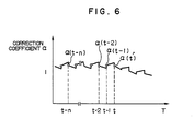
- Fig. 6 shows another way to obtain the learned correction coefficient ⁇ L through learned controlling.
- the time for obtaining values of learned correction coefficient ⁇ L through learned controlling can also be minimized by changing values of the weight coefficients k0, k1, ----- k n and consequently optimum control can be performed through learned controlling within a short period of time following the commencement of use by the user.
- control speed for learned controlling has been described as being set to a high value before the running distance of the vehicle reaches a predetermined value, the frequency of turn-on operations of the ignition switch and start switch may be counted so that when the frequency of the turn-on operations is below a predetermined value, the control speed for learned controlling may be set to a higher value.
- the control speed for learned controlling can readily be set to the higher value before the frequency of the turn-on operations of the ignition switch and start switch, starting from the beginning of re-connection of the battery, reaches the predetermined value.
- automobiles produced in an automobile production factory can be tested in the factory before consignment in a simulation running mode corresponding to a predetermined running mode (Ten mode or LA-4 mode) so as to cause various engine states to occur and accordingly, the engine states can be learned by the automobiles, in advance of consignment thereof, to complete necessary data on the entire area of the RAM.
- a simulation running mode corresponding to a predetermined running mode (Ten mode or LA-4 mode) so as to cause various engine states to occur and accordingly, the engine states can be learned by the automobiles, in advance of consignment thereof, to complete necessary data on the entire area of the RAM.
- the learned controlling has been described as applied to fuel injection, the present invention is not limited thereto but may also be applied to, for example, ignition timing control, air/fuel ratio control, idling control and EGR (Exhaust Gas Recycle) control.
- ignition timing control the O2 sensor 5 may be replaced with a sensor 20 for detecting the combustion state of the engine such as for example a knocking sensor and a combustion pressure sensor.
- the engine control apparatus can be provided wherein the control speed for learned controlling is increased under the predetermined condition to permit optimum engine control through learned controlling within a short period of time following the commencement of use by the user.
Abstract
Description
- This invention relates to an apparatus for controlling an engine such as an internal combustion engine and more particularly to an engine control apparatus having a learned controlling function.
- An engine control apparatus having a learned controlling function is disclosed in, for example, JP-A-59-180048. As is clear from the disclosure of the above public literature, in the conventional engine control apparatus having the learned controlling function, irregularity in characteristics of the engine per se and irregularity and secular variation in characteristics of sensors adapted to detect the status of the engine are corrected using the learned controlling function and various controllable quantities such as for example air/fuel ratio and ignition timing can be controlled optimumly.
- In the conventional engine control apparatus as exemplified in the aforementioned public literature, however, the control speed for learned controlling is unchangeable and it takes a long time to obtain optimum engine control through the learned controlling.
- The control speed for learned controlling is desired to be high during a predetermined condition thereby placing the engine in optimumly controlled condition through the learned controlling within a short period of time following the commencement of use by the user.
- An object of this invention is to provide an engine control apparatus which can obtain, within a relatively short period of time, correction amounts for correcting irregularity in characteristics of the engine per se and irregularity in characteristics of various sensors so as to control the engine optimumly.
- According to the invention, to accomplish the above object, an engine control apparatus for controlling at least the fuel supply amount representative of the controllable quantities by fetching signals from the sensors adapted to detect the status of the engine comprises learned controlling means for controlling the controllable quantity on the basis of the signals from the sensors, and control speed changing means for changing, under a predetermined condition, the control speed for the learned controlling means to a value which is higher than a reference value.
- With this construction, the control speed changing means sets, under the predetermined condition, the control speed for learned controlling to a higher value than the reference value so that the engine can be placed in optimumly controlled condition through the learned controlling within a short period of time following the commencement of use by the user. At the expiration of a predetermined period of time, the control speed for learned controlling is set to the reference value.
-
- Figure 1 is a schematic block diagram showing an engine control apparatus according to an embodiment of the invention.
- Figure 2 is a time chart showing a correction coefficient changing with the operation of the Fig. 1 apparatus.
- Figure 3 is a time chart showing a change in the correction coefficient through learned controlling in the Fig. 1 apparatus.
- Figure 4 illustrates a map of learned correction coefficient data in a RAM obtained through learned controlling in the Fig. 1 apparatus.
- Figure 5 is a flow chart showing the operation of the Fig. 1 apparatus.
- Figure 6 is a time chart showing another example of a change in the correction coefficient through learned controlling in the Fig. 1 apparatus.
- An engine control apparatus according to a preferred embodiment of the invention will now be described with reference to Figs. 1 to 6.
- Firstly, referring to Fig. 1, an
engine 1 has anintake conduit 10 in which an intake airflow rate sensor 2 is disposed having an output terminal connected to a control console 3. Disposed near one end of theintake conduit 10 is aninjector 6 for fuel injection to theengine 1, theinjector 6 having an input terminal connected to the control console 3. - In an exhaust conduit 11 of the
engine 1 is an oxygen (O₂) sensor 5 having an output terminal connected to the control console 3. In this embodiment, the pulse width for fuel injection to theengine 1 is controlled on the basis of a concentration of oxygen in exhaust gas which is detected by the O₂ sensor 5. - A
crank angle sensor 4 rotates in synchronism with the rotation of theengine 1 to produce an engine revolution number signal which is applied to the control console 3, and anodometer 7 is connected to the control console 3 to supply thereto a signal indicative of a running distance of a vehicle. - The engine control apparatus constructed as above operates as will be described below.
- Where QA is the intake air amount which is calculated by the control console 3 on the basis of a flow rate signal measured by the intake air
flow rate sensor 2, N is the engine revolution number (per unit time) which is calculated by the control console 3 on the basis of an engine revolution number signal in the form of pulses produced from thecrank angle sensor 4 each time the engine rotates a predetermined angle and k is a constant, the control console 3 calculates the pulse width TP for fuel injection in accordance with the following equation:
TP = k × QA/N ----- (1) - The fuel injection amount based on the pulse width TP for fuel injection as obtained from equation (1) is feedback controlled using a signal produced from the O₂ sensor 5. More specifically, where α is the feedback correction coefficient and αL is the learned correction coefficient obtained through learned controlling, the control console 3 comprised of a microcomputer calculates the corrected pulse width Ti for fuel injection in accordance with the following equation:
Ti = TP × (α + αL) ----- (2) - The ultimate pulse width for fuel injection to the
injector 6 is controlled pursuant to equation (2). - The correction coefficient α in equation (2) can be obtained through proportional integration control corresponding to the output signal of the O₂ sensor 5, as shown in Fig. 2. More particularly, when the air/fuel ratio changes from "LEAN" to "RICH", for the purpose of rapid controlling, the proportional portion, PR, is subtracted and thereafter the integration portion at the rate of IR is subtracted. Conversely, when the air/fuel ratio changes from "RICH" to "LEAN", for the purpose of rapid controlling, the proportional portion, PL, is added and thereafter the integration portion at the rate of IL is added.
- This conventionally available correction based on the correction coefficient α alone, however, fails to correct errors in controlling attributable to the difference in individuality of the engines per se of vehicles and manufacture errors (irregularity) or secular variation in the various sensors. Accordingly, it has hitherto been also practice to make correction by using the learned correction coefficient αL obtained through learned controlling. The learned correction coefficient αL is defined by an average of values of the correction coefficient α.
- Therefore, when the air/fuel ratio changes from fuel "RICH" to fuel "LEAN" or conversely from fuel "LEAN" to fuel "RICH", values of α are averaged to determine a value of αL as shown in Fig. 3. The value of αL is -αL in this example. Values of the learned correction coefficient αL are obtained in relation to various running states and stored in a
RAM 3A of the control console 3, as shown in Fig. 4. - In Fig. 4, data values of the learned correction coefficient αL are related to the running state in which the engine speed becomes higher as the revolution number N changes to the right on abscissa and the fuel becomes rich, i.e., the load on the engine becomes higher as the pulse width TP for fuel injection changes upwards. Data values αL₁ to αL₂₄ stored in the
RAM 3A in relation to various operation or running states of the engine are not obtained by uniformly averaging values of α. Specifically, data values αL₆, αL₇, αL₁₀, αL₁₁, αL₁₄, αL₁₅, αL₁₈ and αL₁₉ on almost the central area in Fig. 4 are related to engine states which occur relatively frequently and can be obtained by averaging many (for example, ten) values of α. But data values on the peripheral area (for example, αL₁, αL₄, αL₂₁ and αL₂₄) are related to engine states which occur infrequently and if these data values αLi are to be determined by the conventional method which is designed to average, for example, ten values of α, these data values on the peripheral area will remain undetermined for a long time. When under this condition the engine states which are expected to occur infrequently occur, there results a problem that optimum engine controlling can not be performed by the conventional method. - To solve this problem, the present invention features in that, for example, for a small running distance attributed to a new car, in view of the fact that the new car has poor experience in learning, values of α are averaged by a relatively small number (for example, five) to determine data values αLi, whereby data values αLi on the entire area of the map of Fig. 4 can be obtained within a relatively short period of time to meet controlling for any engine states. By using the thus obtained α and αL, the air/fuel ratio can be controlled optimumly pursuant to equation (2).
- Referring to Fig. 5, the operational procedure to this end will be described. In
step 101, the intake air amount QA is calculated in accordance with a flow rate signal produced from the intake airflow rate sensor 2 and instep 102, the engine revolution number N is calculated in accordance with an engine revolution number signal produced from thecrank angle sensor 4. - Subsequently, in
step 103, the pulse width TP for fuel injection is calculated pursuant to equation (1) and instep 104, a signal produced from the O₂ sensor 5 is fetched. Instep 105, the correction coefficient α is calculated on the basis of the signal of the O₂ sensor 5 fetched instep 104 through the proportional integration controlling as previously described in connection with Fig. 2, in a manner well known by itself. - The procedure then proceeds to
step 106 in which it is decided from a running distance signal produced from theodometer 7 whether the running distance of the vehicle is below I Km. - If the running distance of the vehicle is decided to be below I Km in
step 106, the learned correction coefficient αL is calculated, instep 108, pursuant to the following equation:
- If the running distance of the vehicle is decided to exceed I Km in
step 106, the learned correction coefficient αL is calculated, instep 107, pursuant to the following equation:
- Since N₁ in equation (4) is related to N₂ in equation (3) by N₁ »N₂, data values of the learned correction coefficient αL can be calculated and determined through learned controlling within a short period of time.
- Finally, in
step 109, the learned correction coefficient αL determined pursuant to equation (3) or (4) and the correction coefficient α determined instep 105 are used to calculate the pulse width Ti for fuel injection pursuant to equation (2). - As described above, according to this embodiment of the invention, the control speed for learned controlling is set to a higher value before the vehicle reaches a predetermined running distance, thereby ensuring that the air/fuel ratio can be controlled optimumly within a short period of time following the commencement of use by the user.
- Fig. 6 shows another way to obtain the learned correction coefficient αL through learned controlling. In this example, values of α represented by α(t), α(t-1), ----- α(t-n) are multiplied by desired weight coefficients k₀, k₁, ---- kn, respectively, to calculate the learned correction coefficient αL pursuant to the following equation:
αL = k₀·α(t) + k₁·α(t-1) ----- + kn·α(t-n) ----- (5) - In this case, the time for obtaining values of learned correction coefficient αL through learned controlling can also be minimized by changing values of the weight coefficients k₀, k₁, ----- kn and consequently optimum control can be performed through learned controlling within a short period of time following the commencement of use by the user.
- While in the foregoing embodiment the control speed for learned controlling has been described as being set to a high value before the running distance of the vehicle reaches a predetermined value, the frequency of turn-on operations of the ignition switch and start switch may be counted so that when the frequency of the turn-on operations is below a predetermined value, the control speed for learned controlling may be set to a higher value. Through the use of the frequency of the turn-on operations of the ignition switch and start switch in this manner, even when old learned controlling data are destroyed because of disconnection of the battery effected for repair and inspection, the control speed for learned controlling can readily be set to the higher value before the frequency of the turn-on operations of the ignition switch and start switch, starting from the beginning of re-connection of the battery, reaches the predetermined value.
- Particularly, automobiles produced in an automobile production factory can be tested in the factory before consignment in a simulation running mode corresponding to a predetermined running mode (Ten mode or LA-4 mode) so as to cause various engine states to occur and accordingly, the engine states can be learned by the automobiles, in advance of consignment thereof, to complete necessary data on the entire area of the RAM.
- Although in the foregoing embodiment the learned controlling has been described as applied to fuel injection, the present invention is not limited thereto but may also be applied to, for example, ignition timing control, air/fuel ratio control, idling control and EGR (Exhaust Gas Recycle) control. In the case of ignition timing control, the O₂ sensor 5 may be replaced with a
sensor 20 for detecting the combustion state of the engine such as for example a knocking sensor and a combustion pressure sensor. - As has been described, according to the invention, the engine control apparatus can be provided wherein the control speed for learned controlling is increased under the predetermined condition to permit optimum engine control through learned controlling within a short period of time following the commencement of use by the user.
Claims (8)
a plurality of sensors (2, 4, 5) for detecting the operation state of an engine (1);
learned controlling means (105) for correcting a predetermined controllable quantity (TP) on the basis of signals produced from said sensors; and
control speed changing means (108) for setting, under a predetermined condition (7), the control speed for said learned controlling means to a value (N₂) which is higher than a reference value (N₁)
a plurality of sensors (2, 4, 5) for detecting the operation state of an engine (1);
means (105) for calculating, on the basis of signals produced from said sensors, a correction amount (α) which corrects a predetermined controllable quantity;
means (107) for calculating a learned correction amount (αL) by averaging values of the correction amount (α) by a reference occurrence frequency (N₁);
means (108) for calculating, under a predetermined condition, the learned correction amount (αL) by averaging values of the correction amount (α) by an occurrence frequency (N₂) which is smaller than the reference occurrence frequency; and
means (109) for correcting said controllable quantity in accordance with said correction amount (α) and said learned correction amount (αL).
Applications Claiming Priority (2)
| Application Number | Priority Date | Filing Date | Title |
|---|---|---|---|
| JP62056614A JP2555055B2 (en) | 1987-03-13 | 1987-03-13 | Engine controller |
| JP56614/87 | 1987-03-13 |
Publications (3)
| Publication Number | Publication Date |
|---|---|
| EP0282055A2 true EP0282055A2 (en) | 1988-09-14 |
| EP0282055A3 EP0282055A3 (en) | 1989-10-04 |
| EP0282055B1 EP0282055B1 (en) | 1992-05-27 |
Family
ID=13032136
Family Applications (1)
| Application Number | Title | Priority Date | Filing Date |
|---|---|---|---|
| EP88103798A Expired - Lifetime EP0282055B1 (en) | 1987-03-13 | 1988-03-10 | Engine control apparatus |
Country Status (6)
| Country | Link |
|---|---|
| US (1) | US4836169A (en) |
| EP (1) | EP0282055B1 (en) |
| JP (1) | JP2555055B2 (en) |
| KR (1) | KR880011448A (en) |
| CA (1) | CA1297968C (en) |
| DE (1) | DE3871408D1 (en) |
Cited By (1)
| Publication number | Priority date | Publication date | Assignee | Title |
|---|---|---|---|---|
| FR2772079A1 (en) * | 1997-12-08 | 1999-06-11 | Renault | Method and system for fuel injection control in an internal combustion engine. |
Families Citing this family (4)
| Publication number | Priority date | Publication date | Assignee | Title |
|---|---|---|---|---|
| JPH01216054A (en) * | 1988-02-24 | 1989-08-30 | Fuji Heavy Ind Ltd | Controller for fuel injection of engine |
| US5054451A (en) * | 1988-03-25 | 1991-10-08 | Toyota Jidosha Kabushiki Kaisha | Control apparatus for internal combustion |
| US4922877A (en) * | 1988-06-03 | 1990-05-08 | Nissan Motor Company, Limited | System and method for controlling fuel injection quantity for internal combustion engine |
| DE19807215C2 (en) * | 1998-02-20 | 2000-06-08 | Siemens Ag | Control system for an internal combustion engine |
Citations (7)
| Publication number | Priority date | Publication date | Assignee | Title |
|---|---|---|---|---|
| US4181944A (en) * | 1977-07-15 | 1980-01-01 | Hitachi, Ltd. | Apparatus for engine control |
| US4309971A (en) * | 1980-04-21 | 1982-01-12 | General Motors Corporation | Adaptive air/fuel ratio controller for internal combustion engine |
| US4328779A (en) * | 1978-12-07 | 1982-05-11 | Nippon Soken, Inc. | Feedback type ignition timing control system for internal combustion engines |
| EP0145992A2 (en) * | 1983-11-21 | 1985-06-26 | Hitachi, Ltd. | Method of controlling air-fuel ratio |
| GB2162966A (en) * | 1984-07-13 | 1986-02-12 | Fuji Heavy Ind Ltd | Updating of an adaptive mixture control system |
| GB2170859A (en) * | 1984-12-28 | 1986-08-13 | Fuji Heavy Ind Ltd | System for controlling the ignition timing of an internal combustion engine |
| EP0194019A2 (en) * | 1985-02-25 | 1986-09-10 | General Motors Corporation | Engine idle speed control system |
Family Cites Families (5)
| Publication number | Priority date | Publication date | Assignee | Title |
|---|---|---|---|---|
| JPS6088813A (en) * | 1983-10-20 | 1985-05-18 | Mazda Motor Corp | Exhaust purifying device for engine |
| JPS6128739A (en) * | 1984-07-20 | 1986-02-08 | Toyota Motor Corp | Method of controlling learning value for internal-combustion engine |
| JPS61149536A (en) * | 1984-12-25 | 1986-07-08 | Honda Motor Co Ltd | Method of controlling motion control amount of internal-combustion engine with supercharger |
| JPS61152935A (en) * | 1984-12-26 | 1986-07-11 | Fuji Heavy Ind Ltd | Air-fuel ratio controlling device |
| JPS6397843A (en) * | 1986-10-13 | 1988-04-28 | Nippon Denso Co Ltd | Fuel injection control device for internal combustion engine |
-
1987
- 1987-03-13 JP JP62056614A patent/JP2555055B2/en not_active Expired - Lifetime
-
1988
- 1988-02-24 US US07/159,904 patent/US4836169A/en not_active Expired - Lifetime
- 1988-03-02 KR KR1019880002147A patent/KR880011448A/en not_active Application Discontinuation
- 1988-03-10 DE DE8888103798T patent/DE3871408D1/en not_active Expired - Lifetime
- 1988-03-10 CA CA000561069A patent/CA1297968C/en not_active Expired - Lifetime
- 1988-03-10 EP EP88103798A patent/EP0282055B1/en not_active Expired - Lifetime
Patent Citations (7)
| Publication number | Priority date | Publication date | Assignee | Title |
|---|---|---|---|---|
| US4181944A (en) * | 1977-07-15 | 1980-01-01 | Hitachi, Ltd. | Apparatus for engine control |
| US4328779A (en) * | 1978-12-07 | 1982-05-11 | Nippon Soken, Inc. | Feedback type ignition timing control system for internal combustion engines |
| US4309971A (en) * | 1980-04-21 | 1982-01-12 | General Motors Corporation | Adaptive air/fuel ratio controller for internal combustion engine |
| EP0145992A2 (en) * | 1983-11-21 | 1985-06-26 | Hitachi, Ltd. | Method of controlling air-fuel ratio |
| GB2162966A (en) * | 1984-07-13 | 1986-02-12 | Fuji Heavy Ind Ltd | Updating of an adaptive mixture control system |
| GB2170859A (en) * | 1984-12-28 | 1986-08-13 | Fuji Heavy Ind Ltd | System for controlling the ignition timing of an internal combustion engine |
| EP0194019A2 (en) * | 1985-02-25 | 1986-09-10 | General Motors Corporation | Engine idle speed control system |
Cited By (1)
| Publication number | Priority date | Publication date | Assignee | Title |
|---|---|---|---|---|
| FR2772079A1 (en) * | 1997-12-08 | 1999-06-11 | Renault | Method and system for fuel injection control in an internal combustion engine. |
Also Published As
| Publication number | Publication date |
|---|---|
| EP0282055B1 (en) | 1992-05-27 |
| CA1297968C (en) | 1992-03-24 |
| DE3871408D1 (en) | 1992-07-02 |
| JPS63223354A (en) | 1988-09-16 |
| KR880011448A (en) | 1988-10-28 |
| US4836169A (en) | 1989-06-06 |
| EP0282055A3 (en) | 1989-10-04 |
| JP2555055B2 (en) | 1996-11-20 |
Similar Documents
| Publication | Publication Date | Title |
|---|---|---|
| US5542394A (en) | Vehicle engine refueling detection apparatus and method and fuel supply apparatus and method | |
| US6199540B1 (en) | Fuel control system for internal combustion engine | |
| US7040302B2 (en) | Failure diagnosis apparatus for evaporative fuel processing system | |
| US4321903A (en) | Method of feedback controlling air-fuel ratio | |
| US5927260A (en) | Device for diagnosing oxygen sensor deterioration | |
| GB1601384A (en) | Electronic apparatus for feed control of air-gasoline mixture in internal combustion engines | |
| EP0571931B1 (en) | Throttle control apparatus for internal combustion engine | |
| GB2143056A (en) | Automatic control of an internal combustion engine | |
| US5353764A (en) | Electronically controlled fuel supply method and device for internal combustion engine | |
| US5182907A (en) | System for monitoring performance of HC sensors for internal combustion engines | |
| US5777204A (en) | Air-fuel ratio detecting device and method therefor | |
| US5216882A (en) | System for detecting deterioration of HC sensors for internal combustion engines | |
| US5168859A (en) | Method and apparatus for judging misfire in internal combustion engine | |
| EP0440173A2 (en) | Method and apparatus for controlling torque generated in an internal combustion engine | |
| EP0282055A2 (en) | Engine control apparatus | |
| EP0378814B1 (en) | Method of controlling air-fuel ratio | |
| EP0281962A2 (en) | Control apparatus for internal combustion engine | |
| US4878472A (en) | Air-fuel ratio feedback control method for internal combustion engines | |
| US4698765A (en) | Ignition timing control system for an automotive engine | |
| EP0296464A2 (en) | Air/fuel ratio control system for internal combustion engine with correction coefficient learning feature | |
| JP3186250B2 (en) | Air-fuel ratio control device for internal combustion engine | |
| US5834624A (en) | Air-fuel ratio detecting device and method therefor | |
| EP0358062B1 (en) | Method of controlling air-fuel ratio for use in internal combustion engine and apparatus of controlling the same | |
| US4913120A (en) | Air-fuel ratio feedback control method for internal combustion engines | |
| EP0225183B1 (en) | Air-fuel ratio control system for an automotive engine |
Legal Events
| Date | Code | Title | Description |
|---|---|---|---|
| PUAI | Public reference made under article 153(3) epc to a published international application that has entered the european phase |
Free format text: ORIGINAL CODE: 0009012 |
|
| AK | Designated contracting states |
Kind code of ref document: A2 Designated state(s): DE FR GB |
|
| PUAL | Search report despatched |
Free format text: ORIGINAL CODE: 0009013 |
|
| AK | Designated contracting states |
Kind code of ref document: A3 Designated state(s): DE FR GB |
|
| 17P | Request for examination filed |
Effective date: 19890829 |
|
| 17Q | First examination report despatched |
Effective date: 19900207 |
|
| GRAA | (expected) grant |
Free format text: ORIGINAL CODE: 0009210 |
|
| AK | Designated contracting states |
Kind code of ref document: B1 Designated state(s): DE FR GB |
|
| REF | Corresponds to: |
Ref document number: 3871408 Country of ref document: DE Date of ref document: 19920702 |
|
| ET | Fr: translation filed | ||
| PLBE | No opposition filed within time limit |
Free format text: ORIGINAL CODE: 0009261 |
|
| STAA | Information on the status of an ep patent application or granted ep patent |
Free format text: STATUS: NO OPPOSITION FILED WITHIN TIME LIMIT |
|
| 26N | No opposition filed | ||
| PGFP | Annual fee paid to national office [announced via postgrant information from national office to epo] |
Ref country code: FR Payment date: 19940128 Year of fee payment: 7 |
|
| PG25 | Lapsed in a contracting state [announced via postgrant information from national office to epo] |
Ref country code: FR Free format text: LAPSE BECAUSE OF NON-PAYMENT OF DUE FEES Effective date: 19951130 |
|
| REG | Reference to a national code |
Ref country code: FR Ref legal event code: ST |
|
| REG | Reference to a national code |
Ref country code: GB Ref legal event code: IF02 |
|
| PGFP | Annual fee paid to national office [announced via postgrant information from national office to epo] |
Ref country code: GB Payment date: 20020301 Year of fee payment: 15 |
|
| PGFP | Annual fee paid to national office [announced via postgrant information from national office to epo] |
Ref country code: DE Payment date: 20020328 Year of fee payment: 15 |
|
| PG25 | Lapsed in a contracting state [announced via postgrant information from national office to epo] |
Ref country code: GB Free format text: LAPSE BECAUSE OF NON-PAYMENT OF DUE FEES Effective date: 20030310 |
|
| PG25 | Lapsed in a contracting state [announced via postgrant information from national office to epo] |
Ref country code: DE Free format text: LAPSE BECAUSE OF NON-PAYMENT OF DUE FEES Effective date: 20031001 |
|
| GBPC | Gb: european patent ceased through non-payment of renewal fee |
Effective date: 20030310 |