EP0281528A1 - Variable-energy-spark ignition system for internal combustion engines, particularly for motor vehicles - Google Patents
Variable-energy-spark ignition system for internal combustion engines, particularly for motor vehicles Download PDFInfo
- Publication number
- EP0281528A1 EP0281528A1 EP88830074A EP88830074A EP0281528A1 EP 0281528 A1 EP0281528 A1 EP 0281528A1 EP 88830074 A EP88830074 A EP 88830074A EP 88830074 A EP88830074 A EP 88830074A EP 0281528 A1 EP0281528 A1 EP 0281528A1
- Authority
- EP
- European Patent Office
- Prior art keywords
- current
- ignition coil
- primary winding
- engine
- spark
- Prior art date
- Legal status (The legal status is an assumption and is not a legal conclusion. Google has not performed a legal analysis and makes no representation as to the accuracy of the status listed.)
- Granted
Links
- 238000002485 combustion reaction Methods 0.000 title claims description 5
- 238000004804 winding Methods 0.000 claims abstract description 40
- 238000012544 monitoring process Methods 0.000 claims abstract description 11
- 230000015654 memory Effects 0.000 claims description 13
- 230000000875 corresponding effect Effects 0.000 claims description 3
- 230000001960 triggered effect Effects 0.000 claims description 2
- 230000008901 benefit Effects 0.000 description 2
- 238000010586 diagram Methods 0.000 description 2
- 230000006870 function Effects 0.000 description 2
- 230000003466 anti-cipated effect Effects 0.000 description 1
- 238000007796 conventional method Methods 0.000 description 1
- 239000002826 coolant Substances 0.000 description 1
- 230000000694 effects Effects 0.000 description 1
- 238000000034 method Methods 0.000 description 1
- 238000005065 mining Methods 0.000 description 1
- 229920006395 saturated elastomer Polymers 0.000 description 1
- 239000002699 waste material Substances 0.000 description 1
Images
Classifications
-
- F—MECHANICAL ENGINEERING; LIGHTING; HEATING; WEAPONS; BLASTING
- F02—COMBUSTION ENGINES; HOT-GAS OR COMBUSTION-PRODUCT ENGINE PLANTS
- F02P—IGNITION, OTHER THAN COMPRESSION IGNITION, FOR INTERNAL-COMBUSTION ENGINES; TESTING OF IGNITION TIMING IN COMPRESSION-IGNITION ENGINES
- F02P3/00—Other installations
- F02P3/02—Other installations having inductive energy storage, e.g. arrangements of induction coils
- F02P3/04—Layout of circuits
- F02P3/045—Layout of circuits for control of the dwell or anti dwell time
- F02P3/0453—Opening or closing the primary coil circuit with semiconductor devices
- F02P3/0456—Opening or closing the primary coil circuit with semiconductor devices using digital techniques
-
- F—MECHANICAL ENGINEERING; LIGHTING; HEATING; WEAPONS; BLASTING
- F02—COMBUSTION ENGINES; HOT-GAS OR COMBUSTION-PRODUCT ENGINE PLANTS
- F02P—IGNITION, OTHER THAN COMPRESSION IGNITION, FOR INTERNAL-COMBUSTION ENGINES; TESTING OF IGNITION TIMING IN COMPRESSION-IGNITION ENGINES
- F02P17/00—Testing of ignition installations, e.g. in combination with adjusting; Testing of ignition timing in compression-ignition engines
- F02P17/10—Measuring dwell or antidwell time
-
- F—MECHANICAL ENGINEERING; LIGHTING; HEATING; WEAPONS; BLASTING
- F02—COMBUSTION ENGINES; HOT-GAS OR COMBUSTION-PRODUCT ENGINE PLANTS
- F02P—IGNITION, OTHER THAN COMPRESSION IGNITION, FOR INTERNAL-COMBUSTION ENGINES; TESTING OF IGNITION TIMING IN COMPRESSION-IGNITION ENGINES
- F02P3/00—Other installations
- F02P3/02—Other installations having inductive energy storage, e.g. arrangements of induction coils
- F02P3/04—Layout of circuits
- F02P3/05—Layout of circuits for control of the magnitude of the current in the ignition coil
- F02P3/051—Opening or closing the primary coil circuit with semiconductor devices
- F02P3/053—Opening or closing the primary coil circuit with semiconductor devices using digital techniques
-
- F—MECHANICAL ENGINEERING; LIGHTING; HEATING; WEAPONS; BLASTING
- F02—COMBUSTION ENGINES; HOT-GAS OR COMBUSTION-PRODUCT ENGINE PLANTS
- F02P—IGNITION, OTHER THAN COMPRESSION IGNITION, FOR INTERNAL-COMBUSTION ENGINES; TESTING OF IGNITION TIMING IN COMPRESSION-IGNITION ENGINES
- F02P17/00—Testing of ignition installations, e.g. in combination with adjusting; Testing of ignition timing in compression-ignition engines
- F02P17/12—Testing characteristics of the spark, ignition voltage or current
Definitions
- the present invention relates to an internal combustion engine ignition system and, in particular, to a system of the type including at least one spark plug, at least one ignition coil whose primary winding is connectible to the at least one plug to generate a spark, commutator means adapted to assume first and second conditions which respectively permit and interrupt the flow of current in the primary winding of the ignition coil, means for monitoring the intensity of the current flowing in the primary winding of the ignition coil, electrical sensor means for sensing the operating conditions of the engine, and an electronic control unit arranged to pilot the commutator means in a predetermined manner according to the signals provided by the sensor means and by the monitoring means.
- the object of the present invention is to produce an ignition system of the type specified which limits the above inconveniencies of the prior art systems.
- the electronic control unit includes memory means in which there are stored data indicative of predetermined final values of the current in the primary winding of the at least one ignition coil, associated with different operating conditions of the engine identifiable from the signals from the sensor means; the electronic control unit is also able to pilot the commutator means so that each time a spark needs to be generated, the current flow in the primary winding of the ignition coil is interrupted when its intensity has reached the value associated in the memory means with the operating conditions of the engine indicated by the sensor means.
- the system according to the invention thus enables ignition to be achieved with a spark whose energy us "modulated", that is, varied in accordance with the values assumed by the quantities monitored by the sensors associated with the engine.
- the system according to the invention thus reduces the energy dissipated by the controlled commutator device and the average temperature of the ignition coil. Moreover, with the ignition system according to the invention, the plugs presumably have a longer life.
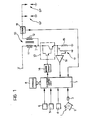
- a sensor of the type known as a phonic wheel is generally indicated 1 and comprises a toothed rotor 2 rotated directly or indirectly by the shaft of an internal combustion engine in known manner, not shown.
- This rotor is inductively coupled to a receiver (pick-up) 3 which, in known manner, outputs a signal whose frequency is indicative of the rate of rotation of the shaft of the internal combustion engine.
- pick-up a receiver
- Reference numeral 4 indicates an electrical sensor for sensing the vacuum in the inlet manifold of the engine.
- Reference numeral 5 indicates a sensor for sensing the temperature of the air intake to the engine, whilst numeral 6 indicates a possible further sensor for sensing the temperature of the engine coolant.
- the pick-up 3 and the sensors 4 to 6 are connected to an electronic microprocessor control unit 7 of known type, having associated memories generally indicated 8.
- An ignition coil generally indicated 10 has a primary winding 11 connected to a voltage source V (for example the battery of the motor vehicle) and a secondary winding 12 selectively connectible to the plugs SP of the engine, for example through a rotary distributor of known type.
- V for example the battery of the motor vehicle
- V for example the battery of the motor vehicle
- the primary winding 11 of the coil 10 is connected to a commutator device generally indicated 13 which in the embodiment shown, includes a pair of Darlington connected transistors which are controlled by the microprocessor unit 7 through a driving circuit 14 of a per se known type.
- a resistor 15 is connected to the emitter of the output transistor of the commutator device 13 so that, in operation, substantially the same current flows in this as in the primary winding 11 of the ignition coil 10.
- the non-earthed terminal of the feedback resistor 15 is connected to an input of a threshold comparator 16 which compares the fall in voltage across the resistor 15 with a reference voltage generated, for example, by a potentiometer 17.
- the comparator 16 supplies a signal to the microprocessor unit 7 when the voltage across the resistor 15 indicates that the current in the primary winding 11 of the ignition coil 10 has reached a predetermin ed threshold value.
- the memory devices 8 of the microprocessor unit 7 there are stored data indicative of predetermined final values of the current in the primary winding of the coil 10, associated with various values or ranges of values assumed by the parameters or quantities monitored by the sensors 4 to 6.
- graphs which correlate the optimal final value of the current in the primary winding of the ignition coil 10 with the values assumed by the quantities monitored by the sensors 3 to 6 are stored in the memories 8 in digital form.
- the control unit 7 is programmed by conventional techniques to saturate and to cut off the Darlington transistor 13 at time deduced by analysis of the signal provided by the pick-up 3.
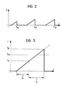
- the current in the primary winding of the ignition coil starts to increase in an approximately linear manner, as indicated, for example, by the wave form shown in Figure 2.
- the time constant, or rate at which the current in the primary winding increases, is linked to the resistance and the inductance of the primary winding and to the resistance of the resistor 15.
- the resistance of the primary winding can vary with changes in temperature.
- the strength of the current at any particular time can also be influenced by variation in the voltage V.
- the control unit 7 is arranged to control the time during which the Darlington transistor 13 remains conductive so that the current in the primary winding 11 of the ignition coil reaches the final value which is associated, in the memories 8, with the values of the quantities registered by the sensors 3 to 6 at that moment.
- the system according to the invention achieves ignition with a spark energy which is variable, and hence optimised, according to the varying operating conditions of the engine. As stated above, this reduces the average temperature of th ignition coil and the energy dissipated by the Darlington transistor 13.
- the microprocessor unit 7 can conveniently be arranged to control the reaching of the required final value of the current in the primary winding of the ignition coil in the following manner.
- the threshold comparator 16 sends a signal to the control unit 7 when the current I in the winding 11 of the ignition coil reaches a threshold value I s ( Figure 3) which is less than the prescribed final minimum value I fm (Figure 3). This happens, for example, after a period of time t o ( Figure 3) from the moment at which current starts to flow.
- the microprocessor unit 7 has an internal clock nd is programmed to evaluate the duration of the interval t o .
- the control unit 7 can, by in terpolation, deduce the duration of the further period of time t1 ( Figure 3) necessary for the current I to reach the final value I fi which is associated, in the memories 8, with the values of the quantities monitored by the sensors 3 to 6 at the time.
- the system according to the invention can also conveniently include electrical monitoring means adapted to provide signals indicative of the "quality" of the sparks triggered by the plugs SP.
- Such monitoring means could, for example, consist of a sensor 18 ( Figure 1) connected to the output of the ignition coil 10 and adapted to provide a signal indicative of (for example, proportional to) the peak value of the high voltage applied to the plugs to trigger the spark.
- the sensor 18, which could, for example, be a potential divider, is connected to the control unit 7. This can further conveniently be programmed to receive the signal output by the sensor 18 and compare it with predetermined reference levels.
- the unit 7 can according to the program stored in its memory, enable the transistor 13 to be conductive until the current in the winding 11 reaches a value corresponding to the value which is associated in the memories 8 with the prevailing operating conditions of the engine, which value is, however, reduced or increased by a correction factor which varies according to the signal provided by the sensor 8.
- This type of feedback control of the current in the winding 11 has advantages in that the energy of the spark can be optimised, not only in dependence on the prevailing operating conditions of the engine, but also on the prevailing conditions of the ignition system.
Landscapes
- Engineering & Computer Science (AREA)
- Chemical & Material Sciences (AREA)
- Combustion & Propulsion (AREA)
- Mechanical Engineering (AREA)
- General Engineering & Computer Science (AREA)
- Ignition Installations For Internal Combustion Engines (AREA)
- Combustion Methods Of Internal-Combustion Engines (AREA)
- Valve Device For Special Equipments (AREA)
- Hybrid Electric Vehicles (AREA)
Abstract
at least one spark plug (SP).
at least one ignition coil (10) whose secondary winding (12) is connectible to the at least one plug (SP) to generate a spark,
at least one controlled commutator device (13) adapted to assume first and second conditions to permit and to interrupt respectively the flow of a current (I) in the primary winding (11) of the at least one ignition coil (10),
a device (15-17) for monitoring the intensity of the current (I) flowing in the primary winding (11) of the ignition coil (10),
electrical sensors (3-6) which provide signals indicative of the operating conditions of the engine, and
an electronic control unit (7) arranged to pilot the commutator device (13) in a predetermined manner according to the signals provided by the sensors (3-6) and by the device (15-17) monitoring the current (I) in the primary winding (11) of the ignition coil (10).
Description
- The present invention relates to an internal combustion engine ignition system and, in particular, to a system of the type including
at least one spark plug,
at least one ignition coil whose primary winding is connectible to the at least one plug to generate a spark,
commutator means adapted to assume first and second conditions which respectively permit and interrupt the flow of current in the primary winding of the ignition coil,
means for monitoring the intensity of the current flowing in the primary winding of the ignition coil,
electrical sensor means for sensing the operating conditions of the engine, and
an electronic control unit arranged to pilot the commutator means in a predetermined manner according to the signals provided by the sensor means and by the monitoring means. - Electronic ignition systems of this type produced up till now tend to effect ignition with a constant discharge or spark energy. These systems are therefore arranged so that the same energy is almost always supplied to the spark plugs. The energy level is necessarily high in order for a spark to be produced under all anticipated operating conditions of the engine. In many situations, therefore, this energy level is somewhat higher than that strictly required to ensure ignition. This obviously results in a waste of energy and in increased stresses on the components of the ignition system, and particularly on the ignition coil (or coils), the plugs and the commutator devices which, in a very large majority of known systems, include a pair of transistors connected in a Darlington arrangement.
- The object of the present invention is to produce an ignition system of the type specified which limits the above inconveniencies of the prior art systems.
- This object is achieved according to the invention by means of an ignition system of the type specified above, whose principal characteristic lies in the fact that the electronic control unit includes memory means in which there are stored data indicative of predetermined final values of the current in the primary winding of the at least one ignition coil, associated with different operating conditions of the engine identifiable from the signals from the sensor means; the electronic control unit is also able to pilot the commutator means so that each time a spark needs to be generated, the current flow in the primary winding of the ignition coil is interrupted when its intensity has reached the value associated in the memory means with the operating conditions of the engine indicated by the sensor means.
- The system according to the invention thus enables ignition to be achieved with a spark whose energy us "modulated", that is, varied in accordance with the values assumed by the quantities monitored by the sensors associated with the engine.
- The system according to the invention thus reduces the energy dissipated by the controlled commutator device and the average temperature of the ignition coil. Moreover, with the ignition system according to the invention, the plugs presumably have a longer life.
- Further characteristics and advantages of the ignition system according to the invention will be seen from the detailed description which follows, with reference to the appended drawings provided purely by way of non-limiting example, in which:
- Figure 1 is an electrical diagram, partly in block form, of an ignition system according to the invention,
- Figure 2 is a graph showing possible current levels I in the primary winding of the ignition coil of the system of Figure 1 as a function of the time t, and
- Figure 3 is an explanatory diagram showing, on an enlarged scale, possible levels of the current I as a function of the time t, useful for understanding the way in which the system according to the invention controls the final value reached by the current in the primary winding of the ignition coil.
- With reference to Figure 1, a sensor of the type known as a phonic wheel is generally indicated 1 and comprises a toothed rotor 2 rotated directly or indirectly by the shaft of an internal combustion engine in known manner, not shown. This rotor is inductively coupled to a receiver (pick-up) 3 which, in known manner, outputs a signal whose frequency is indicative of the rate of rotation of the shaft of the internal combustion engine. Moreover, again in known manner, from the signals it is possible to derive information on the angular position of the shaft of the motor and to determine the moment at which a spark should be produced in the various cylinders from the signals output by the pick-up 3.
- Reference numeral 4 indicates an electrical sensor for sensing the vacuum in the inlet manifold of the engine. Reference numeral 5 indicates a sensor for sensing the temperature of the air intake to the engine, whilst numeral 6 indicates a possible further sensor for sensing the temperature of the engine coolant. The pick-up 3 and the sensors 4 to 6 are connected to an electronic microprocessor control unit 7 of known type, having associated memories generally indicated 8.
- An ignition coil generally indicated 10 has a primary winding 11 connected to a voltage source V (for example the battery of the motor vehicle) and a
secondary winding 12 selectively connectible to the plugs SP of the engine, for example through a rotary distributor of known type. - The primary winding 11 of the
coil 10 is connected to a commutator device generally indicated 13 which in the embodiment shown, includes a pair of Darlington connected transistors which are controlled by the microprocessor unit 7 through adriving circuit 14 of a per se known type. - A
resistor 15 is connected to the emitter of the output transistor of the commutator device 13 so that, in operation, substantially the same current flows in this as in the primary winding 11 of theignition coil 10. The non-earthed terminal of thefeedback resistor 15 is connected to an input of athreshold comparator 16 which compares the fall in voltage across theresistor 15 with a reference voltage generated, for example, by apotentiometer 17. In operation, thecomparator 16 supplies a signal to the microprocessor unit 7 when the voltage across theresistor 15 indicates that the current in the primary winding 11 of theignition coil 10 has reached a predetermin ed threshold value. - In operation, when the Darlington transistor 13 is saturated, a current begins to flow in the primary winding 11 of the ignition coil. This current, whose initial trace is almost linear, increases substantially exponentially.
- When the Darlington transistor is cut off, the current in the primary winding 11 is interrupted and the corresponding high voltage generated in the secondary winding triggers the parks in the plug or plugs SP connected to the
ignition coil 10 at that moment. - In the memory devices 8 of the microprocessor unit 7 there are stored data indicative of predetermined final values of the current in the primary winding of the
coil 10, associated with various values or ranges of values assumed by the parameters or quantities monitored by the sensors 4 to 6. In practice, graphs which correlate the optimal final value of the current in the primary winding of theignition coil 10 with the values assumed by the quantities monitored by the sensors 3 to 6 are stored in the memories 8 in digital form. - The control unit 7 is programmed by conventional techniques to saturate and to cut off the Darlington transistor 13 at time deduced by analysis of the signal provided by the pick-up 3. As stated above, when the Darlington transistor 13 is saturated, the current in the primary winding of the ignition coil starts to increase in an approximately linear manner, as indicated, for example, by the wave form shown in Figure 2. The time constant, or rate at which the current in the primary winding increases, is linked to the resistance and the inductance of the primary winding and to the resistance of the
resistor 15. - Moreover, the resistance of the primary winding can vary with changes in temperature. The strength of the current at any particular time can also be influenced by variation in the voltage V.
- The control unit 7 is arranged to control the time during which the Darlington transistor 13 remains conductive so that the current in the primary winding 11 of the ignition coil reaches the final value which is associated, in the memories 8, with the values of the quantities registered by the sensors 3 to 6 at that moment. In this way, the system according to the invention achieves ignition with a spark energy which is variable, and hence optimised, according to the varying operating conditions of the engine. As stated above, this reduces the average temperature of th ignition coil and the energy dissipated by the Darlington transistor 13.
- The microprocessor unit 7 can conveniently be arranged to control the reaching of the required final value of the current in the primary winding of the ignition coil in the following manner.
- The
threshold comparator 16 sends a signal to the control unit 7 when the current I in the winding 11 of the ignition coil reaches a threshold value Is (Figure 3) which is less than the prescribed final minimum value Ifm (Figure 3). This happens, for example, after a period of time to (Figure 3) from the moment at which current starts to flow. - The microprocessor unit 7 has an internal clock nd is programmed to evaluate the duration of the interval to. On the basis of this information, and by means of a simple predictive algorithm, the control unit 7 can, by in terpolation, deduce the duration of the further period of time t₁ (Figure 3) necessary for the current I to reach the final value Ifi which is associated, in the memories 8, with the values of the quantities monitored by the sensors 3 to 6 at the time.
- It can be seen immediately that this procedure for determining the total time for which current flows in the ignition coil is not influenced by variations in the current I due to variations in the resistance of the winding 11 and/or variations in the voltage V.
- The system according to the invention can also conveniently include electrical monitoring means adapted to provide signals indicative of the "quality" of the sparks triggered by the plugs SP. Such monitoring means could, for example, consist of a sensor 18 (Figure 1) connected to the output of the
ignition coil 10 and adapted to provide a signal indicative of (for example, proportional to) the peak value of the high voltage applied to the plugs to trigger the spark. Thesensor 18, which could, for example, be a potential divider, is connected to the control unit 7. This can further conveniently be programmed to receive the signal output by thesensor 18 and compare it with predetermined reference levels. On the basis of this comparison, the unit 7 can according to the program stored in its memory, enable the transistor 13 to be conductive until the current in the winding 11 reaches a value corresponding to the value which is associated in the memories 8 with the prevailing operating conditions of the engine, which value is, however, reduced or increased by a correction factor which varies according to the signal provided by the sensor 8. This type of feedback control of the current in the winding 11 has advantages in that the energy of the spark can be optimised, not only in dependence on the prevailing operating conditions of the engine, but also on the prevailing conditions of the ignition system.
Claims (5)
at least one spark plug (SP),
at least one ignition coil (10) whose secondary winding (12) is connectible to the at least one spark plug (SP) to induce the generation of a spark,
commutator means (13) adapted to assume first and second conditions which respectively permit and interrupt the flow of a current (I) in the primary winding (11) of the ignition coil (10),
means (15 to 17) for monitoring the current flowing in the primary winding (11) of the ignition coil (10),
electrical sensor means (3 to 6) for sensing the operating conditions of the engine, and
an electronic control unit (7) arranged to pilot the commutator means (13) in a predetermined manner in accordance with the signals provided by the sensor means (3 to 6) and by the monitoring means (15 to 17),
characterised in that the electronic control unit (7) is provided with memory means (8) in which there are stored data indicative of predetermined final values (Ifi) of the current (I) in the primary winding (11) of the ignition coil (10), associated with various operating conditions of the engine identifiable from the signals from the sensor means (3 to 6), the electronic control unit (7) being arranged to pilot the commutator means (13) so that, each time a spark needs to be generated, the current flow in the primary winding (11) of the ignition coil (10) is interrupted when its intensity (I) has reached a value (Ifi) associated in the memory means (8) with the operating conditions of the engine indicated by the sensors (3 to 6).
- to monitor the time (to) taken by the current (I) to reach the threshold value (Is),
- to calculate the further period of time (t₁) necessary for the current (I) to reach the final value (Ifi) associated with the operating conditions of the stored in the memory means (8), and
- to maintain the commutator means (13) in the first condition for the further period of time (t₁).
Priority Applications (1)
| Application Number | Priority Date | Filing Date | Title |
|---|---|---|---|
| AT88830074T ATE99772T1 (en) | 1987-03-02 | 1988-03-01 | ADJUSTABLE ENERGY IGNITION SYSTEM FOR INTERNAL ENGINES. |
Applications Claiming Priority (2)
| Application Number | Priority Date | Filing Date | Title |
|---|---|---|---|
| IT6715387 | 1987-03-02 | ||
| IT8767153A IT1208855B (en) | 1987-03-02 | 1987-03-02 | VARIABLE SPARK ENERGY IGNITION SYSTEM FOR INTERNAL COMBUSTION ENGINES PARTICULARLY FOR MOTOR VEHICLES |
Publications (2)
| Publication Number | Publication Date |
|---|---|
| EP0281528A1 true EP0281528A1 (en) | 1988-09-07 |
| EP0281528B1 EP0281528B1 (en) | 1994-01-05 |
Family
ID=11300031
Family Applications (1)
| Application Number | Title | Priority Date | Filing Date |
|---|---|---|---|
| EP88830074A Expired - Lifetime EP0281528B1 (en) | 1987-03-02 | 1988-03-01 | Variable-energy-spark ignition system for internal combustion engines, particularly for motor vehicles |
Country Status (7)
| Country | Link |
|---|---|
| US (1) | US4915086A (en) |
| EP (1) | EP0281528B1 (en) |
| JP (1) | JP2582840B2 (en) |
| AT (1) | ATE99772T1 (en) |
| DE (1) | DE3886791T2 (en) |
| ES (1) | ES2047577T3 (en) |
| IT (1) | IT1208855B (en) |
Cited By (16)
| Publication number | Priority date | Publication date | Assignee | Title |
|---|---|---|---|---|
| DE4116077A1 (en) * | 1990-05-18 | 1991-11-21 | Hitachi Ltd | IGNITION CURRENT CONTROL ENGINE FOR INTERNAL COMBUSTION ENGINE |
| WO1994003723A1 (en) * | 1992-08-08 | 1994-02-17 | Robert Bosch Gmbh | Sequential spark ignition system for internal combustion engines |
| DE4231954A1 (en) * | 1992-09-24 | 1994-03-31 | Telefunken Microelectron | Ignition energy control for IC engine - has end-stage switching prim. coil current on and off connected via control conduit to control circuit of micro-processor |
| EP0590181A1 (en) * | 1992-09-29 | 1994-04-06 | Siemens Aktiengesellschaft | Method of determination of dwell of a primary circuit of an ignition system of a internal combustion engine |
| EP0555851A3 (en) * | 1992-02-13 | 1994-07-06 | Weber Srl | Ignition control device for an internal combustion engine electronic ignition system |
| WO1995002761A1 (en) * | 1993-07-13 | 1995-01-26 | Jury Alexandrovech Papko | Method and system to control the spark frequency of a multispark ignition system |
| EP0596471A3 (en) * | 1992-11-04 | 1995-02-22 | Vogt Electronic Ag | Alternative current ignition system for combustion engines with control of the ignition energy. |
| EP0655553A1 (en) * | 1993-11-29 | 1995-05-31 | STMicroelectronics S.r.l. | Generation of a diagnostic signal when the current through a power transistor reaches a level close to a limit current |
| WO1997018391A1 (en) * | 1995-11-15 | 1997-05-22 | British Gas Plc | Ignition control circuit for internal combustion engines |
| WO1998019066A1 (en) * | 1996-10-29 | 1998-05-07 | Ficht Gmbh & Co. Kg | Ignition system and principle of operation |
| WO1998045597A1 (en) * | 1997-04-04 | 1998-10-15 | Siemens Aktiengesellschaft | Device for regulating the flow of electricity through a consumer |
| EP0881382A1 (en) * | 1997-05-28 | 1998-12-02 | Sagem Sa | Ignition timing control method for an internal combustion engine |
| WO2002002923A1 (en) * | 2000-06-30 | 2002-01-10 | Robert Bosch Gmbh | Method of ignition and corresponding ignition unit |
| DE19917889B4 (en) * | 1998-04-20 | 2004-07-15 | Cummins Inc., Columbus | Energy controlled ignition system for an internal combustion engine |
| US6796297B2 (en) | 2001-10-23 | 2004-09-28 | Robert Bosch Gmbh | Device for ignition of an internal combustion engine |
| FR2885651A1 (en) * | 2005-09-15 | 2006-11-17 | Siemens Vdo Automotive Sas | Controlling the primary current in an engine's ignition coil comprises providing the engine control unit with a coil performance model relating current intensity to dwell time and measuring dwell times |
Families Citing this family (31)
| Publication number | Priority date | Publication date | Assignee | Title |
|---|---|---|---|---|
| JPH0762468B2 (en) * | 1987-07-01 | 1995-07-05 | 株式会社日立製作所 | Electronic ignition control device for internal combustion engine |
| WO1989008778A1 (en) * | 1988-03-18 | 1989-09-21 | Robert Bosch Gmbh | Cylinder recognition apparatus for a distributorless ignition system |
| DE3902254A1 (en) * | 1989-01-26 | 1990-08-02 | Bosch Gmbh Robert | METHOD FOR ASSIGNING IGNITION SIGNALS TO A REFERENCE CYLINDER |
| JP2878764B2 (en) * | 1990-03-15 | 1999-04-05 | 株式会社日立製作所 | Ignition energization time control device |
| DE4016307C2 (en) * | 1990-05-21 | 2000-03-02 | Bosch Gmbh Robert | Ignition circuit monitoring on an internal combustion engine |
| KR950000221B1 (en) * | 1990-09-27 | 1995-01-12 | 미쓰비시덴키 가부시키가이샤 | Ignition device for internal combustion engine |
| KR960000442B1 (en) * | 1990-11-26 | 1996-01-06 | 미쓰비시덴키 가부시키가이샤 | Ion Current Detector |
| DE4114087A1 (en) * | 1991-04-30 | 1992-11-05 | Vogt Electronic Ag | IGNITION SYSTEM FOR INTERNAL COMBUSTION ENGINES |
| US5283527A (en) * | 1991-06-28 | 1994-02-01 | Ford Motor Company | Methods and apparatus for detecting short circuited secondary coil winding via monitoring primary coil winding |
| US5309888A (en) * | 1991-08-02 | 1994-05-10 | Motorola, Inc. | Ignition system |
| EP0547258B1 (en) * | 1991-12-17 | 1995-06-07 | Siemens Aktiengesellschaft | Ignition device for internal combustion engine |
| US5253475A (en) * | 1992-06-22 | 1993-10-19 | General Motors Corporation | Combustion detection |
| JP2871977B2 (en) * | 1992-11-16 | 1999-03-17 | 三菱電機株式会社 | Internal combustion engine control device |
| DE4328524A1 (en) * | 1993-08-25 | 1995-03-02 | Volkswagen Ag | Controllable ignition system |
| US5392754A (en) * | 1993-12-16 | 1995-02-28 | Delco Electronics Corp. | Method of suppressing ringing in an ignition circuit |
| US5513620A (en) * | 1995-01-26 | 1996-05-07 | Chrysler Corporation | Ignition energy and breakdown voltage circuit and method |
| US6100728A (en) * | 1995-07-31 | 2000-08-08 | Delco Electronics Corp. | Coil current limiting feature for an ignition coil driver module |
| DE19605803A1 (en) * | 1996-02-16 | 1997-08-21 | Daug Deutsche Automobilgesells | Circuit arrangement for ion current measurement |
| RU2127826C1 (en) * | 1997-01-14 | 1999-03-20 | Военный автомобильный институт | Internal combustion engine ignition system |
| FR2768186B1 (en) * | 1997-09-11 | 1999-10-15 | Siemens Automotive Sa | METHOD AND DEVICE FOR DIAGNOSING AN IGNITION SYSTEM FOR AN INTERNAL COMBUSTION ENGINE |
| JP3126689B2 (en) * | 1997-10-27 | 2001-01-22 | 株式会社ケーヒン | Engine control device |
| US6408242B1 (en) | 1997-12-11 | 2002-06-18 | Cummins, Inc. | Apparatus and method for diagnosing and controlling an ignition system of an internal combustion engine |
| US6006156A (en) * | 1997-12-11 | 1999-12-21 | Cummins Engine Company, Inc. | Apparatus and method for diagnosing and controlling an ignition system of an internal combustion engine |
| US6131555A (en) * | 1998-04-20 | 2000-10-17 | Cummins Engine Company, Inc. | System for controlling ignition energy of an internal combustion engine |
| DE19829583C1 (en) * | 1998-07-02 | 1999-10-07 | Daimler Chrysler Ag | Breakthrough voltage determining method for AC ignition system diagnosis in IC engine |
| US6357427B1 (en) | 1999-03-15 | 2002-03-19 | Aerosance, Inc. | System and method for ignition spark energy optimization |
| US9617967B2 (en) | 2013-06-28 | 2017-04-11 | Ford Global Technologies, Llc | Method and system for laser ignition control |
| US9382863B2 (en) | 2013-09-18 | 2016-07-05 | Ford Global Technologies, Llc | Systems and methods for controlling ignition energy during exhaust stroke combustion of gaseous fuel to reduce turbo lag |
| US9303581B2 (en) | 2013-09-18 | 2016-04-05 | Ford Global Technologies, Llc | Systems and methods for injecting gaseous fuel during an exhaust stroke to reduce turbo lag |
| US10495021B2 (en) | 2016-02-09 | 2019-12-03 | Hitachi Automotive Systems, Ltd. | Engine control device |
| CN119878378B (en) * | 2024-12-13 | 2025-12-02 | 陕西航空电气有限责任公司 | A variable-energy ignition circuit for aircraft engines |
Citations (3)
| Publication number | Priority date | Publication date | Assignee | Title |
|---|---|---|---|---|
| US4230078A (en) * | 1977-11-29 | 1980-10-28 | Nippon Soken, Inc. | Ignition control apparatus for internal combustion engine |
| EP0132985A2 (en) * | 1983-07-21 | 1985-02-13 | LUCAS INDUSTRIES public limited company | Internal combustion engine ignition control |
| US4625704A (en) * | 1985-06-28 | 1986-12-02 | Teledyne Industries, Inc. | Electronic ignition system |
Family Cites Families (6)
| Publication number | Priority date | Publication date | Assignee | Title |
|---|---|---|---|---|
| US4377785A (en) * | 1979-07-06 | 1983-03-22 | Nippon Soken, Inc. | Device for diagnosing ignition system for use in internal combustion engine |
| DE3034440A1 (en) * | 1980-09-12 | 1982-04-29 | Robert Bosch Gmbh, 7000 Stuttgart | IGNITION SYSTEM FOR INTERNAL COMBUSTION ENGINES |
| JPS57200669A (en) * | 1981-06-04 | 1982-12-08 | Mitsubishi Electric Corp | Ignition controlling apparatus for internal-combustion engine |
| JPS59128975A (en) * | 1983-01-11 | 1984-07-25 | Nippon Denso Co Ltd | Ignition energy control unit for internal-combustion engine |
| DE3447341C2 (en) * | 1984-12-24 | 1995-11-30 | Bosch Gmbh Robert | Method for controlling the closing angle of a spark ignition internal combustion engine |
| US4750467A (en) * | 1986-09-11 | 1988-06-14 | General Motors Corporation | Internal combustion engine ignition system |
-
1987
- 1987-03-02 IT IT8767153A patent/IT1208855B/en active
-
1988
- 1988-03-01 ES ES88830074T patent/ES2047577T3/en not_active Expired - Lifetime
- 1988-03-01 EP EP88830074A patent/EP0281528B1/en not_active Expired - Lifetime
- 1988-03-01 JP JP63048534A patent/JP2582840B2/en not_active Expired - Lifetime
- 1988-03-01 AT AT88830074T patent/ATE99772T1/en not_active IP Right Cessation
- 1988-03-01 DE DE3886791T patent/DE3886791T2/en not_active Expired - Fee Related
- 1988-03-02 US US07/163,333 patent/US4915086A/en not_active Expired - Fee Related
Patent Citations (3)
| Publication number | Priority date | Publication date | Assignee | Title |
|---|---|---|---|---|
| US4230078A (en) * | 1977-11-29 | 1980-10-28 | Nippon Soken, Inc. | Ignition control apparatus for internal combustion engine |
| EP0132985A2 (en) * | 1983-07-21 | 1985-02-13 | LUCAS INDUSTRIES public limited company | Internal combustion engine ignition control |
| US4625704A (en) * | 1985-06-28 | 1986-12-02 | Teledyne Industries, Inc. | Electronic ignition system |
Non-Patent Citations (2)
| Title |
|---|
| PATENT ABSTRACTS OF JAPAN, vol. 4, no. 33 (M-3)[515], 21st March 1980, page 102 M 3; & JP-A-55 007 921 (NIPPON DENSO K.K.) 21-01-1980 * |
| PATENT ABSTRACTS OF JAPAN, vol. 9, no. 272 (M-425)[1995], 30th October 1985, page 99 M 425; & JP-A-60 116 863 (NIPPON DENSO K.K.) 24-06-1985 * |
Cited By (25)
| Publication number | Priority date | Publication date | Assignee | Title |
|---|---|---|---|---|
| DE4116077C2 (en) * | 1990-05-18 | 1999-05-12 | Hitachi Ltd | Device for controlling the passage time of the ignition current for an internal combustion engine |
| DE4116077A1 (en) * | 1990-05-18 | 1991-11-21 | Hitachi Ltd | IGNITION CURRENT CONTROL ENGINE FOR INTERNAL COMBUSTION ENGINE |
| EP0555851A3 (en) * | 1992-02-13 | 1994-07-06 | Weber Srl | Ignition control device for an internal combustion engine electronic ignition system |
| WO1994003723A1 (en) * | 1992-08-08 | 1994-02-17 | Robert Bosch Gmbh | Sequential spark ignition system for internal combustion engines |
| US5488940A (en) * | 1992-08-08 | 1996-02-06 | Robert Bosch Gmbh | Ignition system for internal combustion engines |
| DE4231954A1 (en) * | 1992-09-24 | 1994-03-31 | Telefunken Microelectron | Ignition energy control for IC engine - has end-stage switching prim. coil current on and off connected via control conduit to control circuit of micro-processor |
| EP0590181A1 (en) * | 1992-09-29 | 1994-04-06 | Siemens Aktiengesellschaft | Method of determination of dwell of a primary circuit of an ignition system of a internal combustion engine |
| EP0596471A3 (en) * | 1992-11-04 | 1995-02-22 | Vogt Electronic Ag | Alternative current ignition system for combustion engines with control of the ignition energy. |
| US5505175A (en) * | 1992-11-04 | 1996-04-09 | Vogt Electronic Ag | Ignition system for internal combustion engine |
| WO1995002761A1 (en) * | 1993-07-13 | 1995-01-26 | Jury Alexandrovech Papko | Method and system to control the spark frequency of a multispark ignition system |
| EP0655553A1 (en) * | 1993-11-29 | 1995-05-31 | STMicroelectronics S.r.l. | Generation of a diagnostic signal when the current through a power transistor reaches a level close to a limit current |
| US5617046A (en) * | 1993-11-29 | 1997-04-01 | Sgs-Thomson Microelectronics, S.R.L. | Generation of a diagnostic signal when the current through a power transistor reaches a level close to a limit current |
| GB2307516B (en) * | 1995-11-15 | 1999-06-02 | British Gas Plc | Ignition control circuit for internal combustion engines |
| US5896848A (en) * | 1995-11-15 | 1999-04-27 | Bg Plc | Ignition control circuit for internal combustion engine |
| WO1997018391A1 (en) * | 1995-11-15 | 1997-05-22 | British Gas Plc | Ignition control circuit for internal combustion engines |
| WO1998019066A1 (en) * | 1996-10-29 | 1998-05-07 | Ficht Gmbh & Co. Kg | Ignition system and principle of operation |
| WO1998045597A1 (en) * | 1997-04-04 | 1998-10-15 | Siemens Aktiengesellschaft | Device for regulating the flow of electricity through a consumer |
| US6204693B1 (en) | 1997-04-04 | 2001-03-20 | Siemens Aktiengesellschaft | Apparatus for regulating the flow of current through a load |
| EP0881382A1 (en) * | 1997-05-28 | 1998-12-02 | Sagem Sa | Ignition timing control method for an internal combustion engine |
| FR2764004A1 (en) * | 1997-05-28 | 1998-12-04 | Sagem | METHOD FOR CONTROLLING THE IGNITION OF AN INTERNAL COMBUSTION ENGINE |
| DE19917889B4 (en) * | 1998-04-20 | 2004-07-15 | Cummins Inc., Columbus | Energy controlled ignition system for an internal combustion engine |
| WO2002002923A1 (en) * | 2000-06-30 | 2002-01-10 | Robert Bosch Gmbh | Method of ignition and corresponding ignition unit |
| US6814047B2 (en) | 2000-06-30 | 2004-11-09 | Robert Bosch Gmbh | Method of ignition and corresponding ignition unit |
| US6796297B2 (en) | 2001-10-23 | 2004-09-28 | Robert Bosch Gmbh | Device for ignition of an internal combustion engine |
| FR2885651A1 (en) * | 2005-09-15 | 2006-11-17 | Siemens Vdo Automotive Sas | Controlling the primary current in an engine's ignition coil comprises providing the engine control unit with a coil performance model relating current intensity to dwell time and measuring dwell times |
Also Published As
| Publication number | Publication date |
|---|---|
| DE3886791D1 (en) | 1994-02-17 |
| EP0281528B1 (en) | 1994-01-05 |
| IT8767153A0 (en) | 1987-03-02 |
| ES2047577T3 (en) | 1994-03-01 |
| ATE99772T1 (en) | 1994-01-15 |
| JPS63246469A (en) | 1988-10-13 |
| JP2582840B2 (en) | 1997-02-19 |
| IT1208855B (en) | 1989-07-10 |
| US4915086A (en) | 1990-04-10 |
| DE3886791T2 (en) | 1994-05-19 |
Similar Documents
| Publication | Publication Date | Title |
|---|---|---|
| EP0281528A1 (en) | Variable-energy-spark ignition system for internal combustion engines, particularly for motor vehicles | |
| US5127388A (en) | Ignition system for an internal combustion engine | |
| US4333334A (en) | Knocking discrimination apparatus | |
| US20020066444A1 (en) | Ion current detection system and method for internal combustion engine | |
| US6539930B2 (en) | Ignition apparatus for internal combustion engine | |
| US3884203A (en) | Engine RPM control system | |
| US9890757B2 (en) | Electronic control of a spark plug for an internal combustion engine | |
| US4178893A (en) | Ignition control apparatus for an internal combustion engine | |
| US5634453A (en) | Ignition apparatus for internal combustion engine | |
| US4167927A (en) | Contactless ignition control system with a dwell time control circuit for an internal combustion engine | |
| KR20010033597A (en) | Method and device for regulating power in ignition systems with a primary-side short-circuiting switch | |
| EP0657645A2 (en) | Overheat detecting apparatus for engine | |
| CA1132661A (en) | Resistive device sensor | |
| US5090386A (en) | Fuel injection control system for an internal combustion engine | |
| GB1583307A (en) | Ignition circuit for internal combustion engines | |
| EP0555851A2 (en) | Ignition control device for an internal combustion engine electronic ignition system | |
| US5048486A (en) | Ignition circuit with timing control | |
| EP0748449B1 (en) | Speed sensor and conditioning circuit | |
| EP0323412A2 (en) | An ignition system for an internal combustion engine for motor vehicles, particularly of the static-distribution type | |
| US4053823A (en) | Ignition arc monitor circuit | |
| US4249498A (en) | Apparatus for correcting a fuel apportionment signal in an internal combustion engine | |
| US4799471A (en) | Electronic system for controlling the ignition of an internal combustion engine, particularly for motor vehicles | |
| WO1992021876A1 (en) | Diagnostic system for a capacitor discharge ignition system | |
| EP0663526A2 (en) | Internal combustion engine ignition system | |
| JPH05312094A (en) | Gasoline engine combustion condition detector |
Legal Events
| Date | Code | Title | Description |
|---|---|---|---|
| PUAI | Public reference made under article 153(3) epc to a published international application that has entered the european phase |
Free format text: ORIGINAL CODE: 0009012 |
|
| AK | Designated contracting states |
Kind code of ref document: A1 Designated state(s): AT BE CH DE ES FR GB IT LI NL SE |
|
| 17P | Request for examination filed |
Effective date: 19890227 |
|
| 17Q | First examination report despatched |
Effective date: 19920413 |
|
| RAP1 | Party data changed (applicant data changed or rights of an application transferred) |
Owner name: MARELLI AUTRONICA S.P.A. |
|
| GRAA | (expected) grant |
Free format text: ORIGINAL CODE: 0009210 |
|
| AK | Designated contracting states |
Kind code of ref document: B1 Designated state(s): AT BE CH DE ES FR GB IT LI NL SE |
|
| PG25 | Lapsed in a contracting state [announced via postgrant information from national office to epo] |
Ref country code: NL Effective date: 19940105 Ref country code: LI Effective date: 19940105 Ref country code: CH Effective date: 19940105 Ref country code: BE Effective date: 19940105 Ref country code: AT Effective date: 19940105 |
|
| REF | Corresponds to: |
Ref document number: 99772 Country of ref document: AT Date of ref document: 19940115 Kind code of ref document: T |
|
| ITF | It: translation for a ep patent filed | ||
| REF | Corresponds to: |
Ref document number: 3886791 Country of ref document: DE Date of ref document: 19940217 |
|
| REG | Reference to a national code |
Ref country code: ES Ref legal event code: FG2A Ref document number: 2047577 Country of ref document: ES Kind code of ref document: T3 |
|
| REG | Reference to a national code |
Ref country code: CH Ref legal event code: PL |
|
| ET | Fr: translation filed | ||
| NLV1 | Nl: lapsed or annulled due to failure to fulfill the requirements of art. 29p and 29m of the patents act | ||
| PLBE | No opposition filed within time limit |
Free format text: ORIGINAL CODE: 0009261 |
|
| STAA | Information on the status of an ep patent application or granted ep patent |
Free format text: STATUS: NO OPPOSITION FILED WITHIN TIME LIMIT |
|
| 26N | No opposition filed | ||
| EAL | Se: european patent in force in sweden |
Ref document number: 88830074.6 |
|
| PGFP | Annual fee paid to national office [announced via postgrant information from national office to epo] |
Ref country code: SE Payment date: 20000207 Year of fee payment: 13 |
|
| PGFP | Annual fee paid to national office [announced via postgrant information from national office to epo] |
Ref country code: GB Payment date: 20000222 Year of fee payment: 13 |
|
| PGFP | Annual fee paid to national office [announced via postgrant information from national office to epo] |
Ref country code: ES Payment date: 20000223 Year of fee payment: 13 |
|
| PGFP | Annual fee paid to national office [announced via postgrant information from national office to epo] |
Ref country code: DE Payment date: 20000228 Year of fee payment: 13 |
|
| PGFP | Annual fee paid to national office [announced via postgrant information from national office to epo] |
Ref country code: FR Payment date: 20000330 Year of fee payment: 13 |
|
| PG25 | Lapsed in a contracting state [announced via postgrant information from national office to epo] |
Ref country code: GB Free format text: LAPSE BECAUSE OF NON-PAYMENT OF DUE FEES Effective date: 20010301 |
|
| PG25 | Lapsed in a contracting state [announced via postgrant information from national office to epo] |
Ref country code: SE Free format text: LAPSE BECAUSE OF NON-PAYMENT OF DUE FEES Effective date: 20010302 Ref country code: ES Free format text: LAPSE BECAUSE OF NON-PAYMENT OF DUE FEES Effective date: 20010302 |
|
| GBPC | Gb: european patent ceased through non-payment of renewal fee |
Effective date: 20010301 |
|
| EUG | Se: european patent has lapsed |
Ref document number: 88830074.6 |
|
| PG25 | Lapsed in a contracting state [announced via postgrant information from national office to epo] |
Ref country code: FR Free format text: LAPSE BECAUSE OF NON-PAYMENT OF DUE FEES Effective date: 20011130 |
|
| REG | Reference to a national code |
Ref country code: FR Ref legal event code: ST |
|
| PG25 | Lapsed in a contracting state [announced via postgrant information from national office to epo] |
Ref country code: DE Free format text: LAPSE BECAUSE OF NON-PAYMENT OF DUE FEES Effective date: 20020101 |
|
| REG | Reference to a national code |
Ref country code: ES Ref legal event code: FD2A Effective date: 20020411 |
|
| PG25 | Lapsed in a contracting state [announced via postgrant information from national office to epo] |
Ref country code: IT Free format text: LAPSE BECAUSE OF NON-PAYMENT OF DUE FEES;WARNING: LAPSES OF ITALIAN PATENTS WITH EFFECTIVE DATE BEFORE 2007 MAY HAVE OCCURRED AT ANY TIME BEFORE 2007. THE CORRECT EFFECTIVE DATE MAY BE DIFFERENT FROM THE ONE RECORDED. Effective date: 20050301 |