EP0281405A2 - Oxyhydrogen catalytic thermal tip for angioplasty and the like - Google Patents
Oxyhydrogen catalytic thermal tip for angioplasty and the like Download PDFInfo
- Publication number
- EP0281405A2 EP0281405A2 EP88301882A EP88301882A EP0281405A2 EP 0281405 A2 EP0281405 A2 EP 0281405A2 EP 88301882 A EP88301882 A EP 88301882A EP 88301882 A EP88301882 A EP 88301882A EP 0281405 A2 EP0281405 A2 EP 0281405A2
- Authority
- EP
- European Patent Office
- Prior art keywords
- catheter
- chamber
- tip
- accordance
- catalytic
- Prior art date
- Legal status (The legal status is an assumption and is not a legal conclusion. Google has not performed a legal analysis and makes no representation as to the accuracy of the status listed.)
- Ceased
Links
Images
Classifications
-
- A—HUMAN NECESSITIES
- A61—MEDICAL OR VETERINARY SCIENCE; HYGIENE
- A61B—DIAGNOSIS; SURGERY; IDENTIFICATION
- A61B18/00—Surgical instruments, devices or methods for transferring non-mechanical forms of energy to or from the body
-
- A—HUMAN NECESSITIES
- A61—MEDICAL OR VETERINARY SCIENCE; HYGIENE
- A61B—DIAGNOSIS; SURGERY; IDENTIFICATION
- A61B17/00—Surgical instruments, devices or methods, e.g. tourniquets
- A61B17/22—Implements for squeezing-off ulcers or the like on the inside of inner organs of the body; Implements for scraping-out cavities of body organs, e.g. bones; Calculus removers; Calculus smashing apparatus; Apparatus for removing obstructions in blood vessels, not otherwise provided for
-
- A—HUMAN NECESSITIES
- A61—MEDICAL OR VETERINARY SCIENCE; HYGIENE
- A61B—DIAGNOSIS; SURGERY; IDENTIFICATION
- A61B18/00—Surgical instruments, devices or methods for transferring non-mechanical forms of energy to or from the body
- A61B18/04—Surgical instruments, devices or methods for transferring non-mechanical forms of energy to or from the body by heating
- A61B18/06—Surgical instruments, devices or methods for transferring non-mechanical forms of energy to or from the body by heating caused by chemical reaction, e.g. moxaburners
-
- A—HUMAN NECESSITIES
- A61—MEDICAL OR VETERINARY SCIENCE; HYGIENE
- A61B—DIAGNOSIS; SURGERY; IDENTIFICATION
- A61B17/00—Surgical instruments, devices or methods, e.g. tourniquets
- A61B2017/00017—Electrical control of surgical instruments
- A61B2017/00022—Sensing or detecting at the treatment site
- A61B2017/00084—Temperature
- A61B2017/00092—Temperature using thermocouples
-
- A—HUMAN NECESSITIES
- A61—MEDICAL OR VETERINARY SCIENCE; HYGIENE
- A61B—DIAGNOSIS; SURGERY; IDENTIFICATION
- A61B17/00—Surgical instruments, devices or methods, e.g. tourniquets
- A61B17/00234—Surgical instruments, devices or methods, e.g. tourniquets for minimally invasive surgery
- A61B2017/00292—Surgical instruments, devices or methods, e.g. tourniquets for minimally invasive surgery mounted on or guided by flexible, e.g. catheter-like, means
-
- A—HUMAN NECESSITIES
- A61—MEDICAL OR VETERINARY SCIENCE; HYGIENE
- A61B—DIAGNOSIS; SURGERY; IDENTIFICATION
- A61B18/00—Surgical instruments, devices or methods for transferring non-mechanical forms of energy to or from the body
- A61B18/04—Surgical instruments, devices or methods for transferring non-mechanical forms of energy to or from the body by heating
- A61B18/06—Surgical instruments, devices or methods for transferring non-mechanical forms of energy to or from the body by heating caused by chemical reaction, e.g. moxaburners
- A61B2018/066—Surgical instruments, devices or methods for transferring non-mechanical forms of energy to or from the body by heating caused by chemical reaction, e.g. moxaburners one of the reactants being oxygen not from the air
-
- A—HUMAN NECESSITIES
- A61—MEDICAL OR VETERINARY SCIENCE; HYGIENE
- A61B—DIAGNOSIS; SURGERY; IDENTIFICATION
- A61B2217/00—General characteristics of surgical instruments
- A61B2217/002—Auxiliary appliance
- A61B2217/005—Auxiliary appliance with suction drainage system
-
- A—HUMAN NECESSITIES
- A61—MEDICAL OR VETERINARY SCIENCE; HYGIENE
- A61B—DIAGNOSIS; SURGERY; IDENTIFICATION
- A61B2217/00—General characteristics of surgical instruments
- A61B2217/002—Auxiliary appliance
- A61B2217/007—Auxiliary appliance with irrigation system
-
- A—HUMAN NECESSITIES
- A61—MEDICAL OR VETERINARY SCIENCE; HYGIENE
- A61B—DIAGNOSIS; SURGERY; IDENTIFICATION
- A61B2218/00—Details of surgical instruments, devices or methods for transferring non-mechanical forms of energy to or from the body
- A61B2218/001—Details of surgical instruments, devices or methods for transferring non-mechanical forms of energy to or from the body having means for irrigation and/or aspiration of substances to and/or from the surgical site
- A61B2218/007—Aspiration
- A61B2218/008—Aspiration for smoke evacuation
Definitions
- the present invention relates to thermal tip catheter surgical devices especially for performing thermal angioplasty including removing obstructed atherosclerotic lesions in arteries and ablating arrhythmogenic foci in cardiac tissues, and for cauterization of bleeding vessels; and, more particularly, to thermal tip catheters utilizing catalytic reactions to thermally power or heat the catheter tip.
- thermal tip catheter or the like system has previously been available for successful angioplasty which does not require electrical or laser energy to heat the catheter tip.
- the need exists for a thermal tip angioplastic device which is safe, effective, less expensive, and easy to operate with minimal technical and support staff.
- catalytic thermal tip catheter employing a temperature monitoring capability to monitor the heat generated during catalytic reactions; to provide a catalytic thermal tip catheter including a vacuum disposal system; and to provide a catalytic thermal tip catheter system which will guide the rate of tissue ablation and avoid vessel wall perforation during angioplasty through the utilization of a monitoring/controlling system.
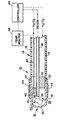
- the single figure shows a partial cross-sectional view of the catalytic thermal tip catheter of the present invention, particularly illustrating the working end of the catheter.
- a preferred embodiment 10 of the present invention is schematically illustrated in the sole figure, and includes a catheter body 14 provided with a catalytic thermal tip 12 at its working end.
- the body 14 of the catheter 10 includes an outer tubing 18 having a distal end 16 which is slid over the proximal open end 22 of a metallic tip 20 which defines the thermal tip 12 with a chamber 28 therewithin.
- An inner tubing 24 is coaxially mounted within the outer tubing 18, the inner tubing 24 having an open distal end 26 positioned at a fixed distance from the metallic tip 20.
- a suitable catalyst such as a palladium sponge 30.
- the metallic tip 20 is desirably formed of surgical grade stainless steel, although other inert metals or even non-metallic materials of good heat resistance and heat conductivity could be used.
- Tubing 18 and 24 of the catheter 10 are preferably formed of polytetrafluoroethylene (TM-Teflon) but other inert and heat resistant materials can be used as long as the tubing is of a diameter to permit invasive passage of the catheter through blood vessels and arteries, and if the material under those conditions is sufficiently rigid so as to maintain a circular cross-section while being sufficiently flexible to function properly as a blood vessel catheter.
- TM-Teflon polytetrafluoroethylene
- polyimides and certain heat resistant silicon resins can be used instead of Teflon.
- Inner tubing 24, near its distal open end 26, is supported by any suitable means such as an annular through-hole collar or the like for securing the tubing distal end 26 at a fixed distance from the interior surface of the metallic tip 20.
- spacing is provided simply by the welding of two axially extending pins, rods or wires 32 to the inner surface of the metallic tip 20 near its proximal end 22, the wires 32 being spaced roughly 180° from one another.
- axial through-openings must be provided to permit passage of reactive gases from the proximal end of the catheter 10 to the reaction cavity 28 at the distal end 12 downstream of the spacer.
- thermocouple 40 or the like having a sensor 42 at its end, the thermocouple 40 passing through such a through-opening and the sensor 42 being positioned within the reaction cavity 28.
- the inner tubing 24 provides a conduit for applying a vacuum from the proximal end to the reaction cavity 28, particularly employed to dispose of gases and vapors generated during catalytic reactions carried out in the catalytic chamber 28.
- the metallic tip 20 is connected to the open distal end of the outer tubing 18 as shown and described above, and is annularly sealed via, for instance, a metal ring constrictor 44 which provides a tight fluid seal during operation at high temperatures. Due to the high coefficient of heat of expansion of Teflon, the seal 44 becomes tighter as the tip 20 is heated and expansion occurs.
- the metallic tip 20 is extremely small, having a diameter of approximately 0.9 mm, and it will be consequently understood that all the parts are small and the drawing is on an enlarged scale.
- the device of the present invention preferably utilizes the combustion of oxygen and hydrogen reactive gases as the energy source to heat the metallic tip 20.
- Oxygen and hydrogen gases are suitably generated near the proximal end of the device using typical electrolytic processes; alternatively, the gases may be made elsewhere and stored, although this option is less safe.
- a stoichiometric ratio of oxyhydrogen is passed down the annular space of the catheter 10 between the outer tubing 18 and the inner tubing 24.
- the amount of gases delivered to the annular space may be controlled by a manual or automatic controller 46 which is in direct communication with a temperature monitoring system 48, the monitoring system being connected to the thermocouple assembly 40.
- the oxyhydrogen gas reaches the catalytic chamber 28, encased by the metallic tip 20, where a piece of palladium sponge 30 resides, and chemical combustion is started by the catalytic action of the palladium sponge on the mixture of oxygen and hydrogen.
- H2 hydrogen gas
- O2 oxygen gas
- 136 calories or 568 joules of energy in the form of heat are delivered by convection to the metallic tip 20 and then by conduction through the metallic tip 20 to the locus of surgery.
- the water vapor or steam formed within the chamber 28 by the reaction of H2 and O2 is evacuated through the inner tubing 24 by means of a vacuum applied to its distal end 26 from its proximal end.
- This vacuum may also be regulated by the controller 46. Without evacuating the formed steam rapidly, the water vapor condenses to form liquid water which may wet and inhibit the catalytic activity of the palladium sponge 30, thus making it difficult to later reinitiate the chemical combustion.
- the double catheter system gives the added advantage of the well-known countercurrent heat exchange system.
- the oxyhydrogen passing down the annular space between the outer tubing 18 and the inner tubing 24 is progressively heated by the high temperature steam that is evacuated through the inner tubing 24. Increased efficiency of combustion of the hydrogen is thus achieved, and the heat of the water vapor is dissipated to the incoming gases and not to the surrounding tissue along the length of the catheter body 14.
- the amount of heating of the metallic tip 20 is regulated easily by the amount of oxyhydrogen delivered through the catheter, via controller 46.
- the thermocouple sensor 42 positioned within the catalytic chamber 28 provides a feedback signal to control the amount of gas delivered.
- the controller 46 regulates the amount of heating and minimizes any unwanted tissue injury.
- the device needs to be heat activated initially to dry the palladium sponge prior to operation. Heat activation is performed simply by heating the metallic tip with either a heating gun (e.g., a hair dryer), hot plate, or gas flame to approximately 80°C. Once activated, the device can operate without reactivation even if the oxyhydrogen gas has been turned off for 10-15 minutes. In addition, reactivation is never a problem if the metallic tip temperature is maintained above 35-40°C.
- a heating gun e.g., a hair dryer
- hot plate e.g., a hot plate
- gas flame e.g., a gas flame
- catalytic materials for the sponge may be employed.
- a platinum sponge may be used, as opposed to a palladium sponge, to react with the oxyhydrogen gas.
- reactive fluids other than oxygen and hydrogen may be employed to react with a catalyst situated in the catalytic chamber.
- the catalytic thermal tip catheter is safe, inexpensive, and results in efficacious tissue ablation which can be easily and effectively regulated by temperature feedback monitoring, and therefore the present invention is an excellent alternative to laser and electrical thermal angioplasty.
Landscapes
- Health & Medical Sciences (AREA)
- Surgery (AREA)
- Life Sciences & Earth Sciences (AREA)
- Molecular Biology (AREA)
- General Health & Medical Sciences (AREA)
- Veterinary Medicine (AREA)
- Engineering & Computer Science (AREA)
- Biomedical Technology (AREA)
- Heart & Thoracic Surgery (AREA)
- Medical Informatics (AREA)
- Public Health (AREA)
- Animal Behavior & Ethology (AREA)
- Nuclear Medicine, Radiotherapy & Molecular Imaging (AREA)
- Orthopedic Medicine & Surgery (AREA)
- Vascular Medicine (AREA)
- Otolaryngology (AREA)
- Media Introduction/Drainage Providing Device (AREA)
- Thermotherapy And Cooling Therapy Devices (AREA)
- Organic Low-Molecular-Weight Compounds And Preparation Thereof (AREA)
- Materials For Medical Uses (AREA)
Abstract
Description
- The present invention relates to thermal tip catheter surgical devices especially for performing thermal angioplasty including removing obstructed atherosclerotic lesions in arteries and ablating arrhythmogenic foci in cardiac tissues, and for cauterization of bleeding vessels; and, more particularly, to thermal tip catheters utilizing catalytic reactions to thermally power or heat the catheter tip.
- Medical science, and especially the practice of angioplastic surgery, has experienced dramatic advances during the past several decades. More recently, the use of thermally-heated metallic tips for catheters has been suggested for ablating human atherosclerotic plaques and recanalizing obstructed low risk peripheral arteries. Those thermal tip catheters which have been so used require electrical or laser energy to heat the catheter tip to a desired temperature for carrying out the desired thermal surgery.
- For example, experimental laser thermal angioplasty has been successfully performed in human peripheral arteries with low risks of vessel perforation (Sanborn et al, JACC 1985; 4:934-8), and preliminary studies regarding laser thermal angioplasty are ongoing in patients with coronary artery disease (Lancet 1986 II: 214-5; and Cumberland et al, Lancet 1986 I: 1457-9). In addition, electrical thermal tip catheters have also been designed and feasibility studies are being carried out (Lu et al, abstr. circ. 1986); these require about 10-15 watts for effective tissue ablation.
- However, while electrical and laser thermal angioplasty has greatly improved, has achieved limited success and has some potential, the danger of exposing unnecessary electrical shock and other injuries to patients, particularly due to an electrical source or laser operating in a patient's blood vessels, is still a major undesired probability. Electrical and laser thermal angioplastic apparatus also have minimal control over the rate of tissue ablation due to lack of temperature monitoring of the working (distal) end or tip of the catheter.
- Furthermore, when employing laser thermal angioplasty, a large technical and support staff are usually required to operate the laser apparatus effectively and safely. Moreover, laser system are necessarily cumbersome and nonportable, therefore restricting their practicality. Both the electrical and the laser thermal tip catheter systems are expensive to manufacture and require regular upkeep and maintenance to assure system operation and patient safety.
- No thermal tip catheter or the like system has previously been available for successful angioplasty which does not require electrical or laser energy to heat the catheter tip. The need exists for a thermal tip angioplastic device which is safe, effective, less expensive, and easy to operate with minimal technical and support staff.
- Accordingly, it is an object of the present invention to eliminate and overcome the deficiencies and disadvantages of the prior art, such as those set forth above.
- It is another object of the invention to provide for improved, safer and less expensive angioplastic surgery.
- It is a further object of the present invention to provide an improved thermal tip catheter for performing angioplasty and the like.
- It is yet another object of the present invention to provide a thermal tip catheter which utilizes a catalytic exothermic reaction to heat the catheter tip.
- It is yet a further object of the present invention to provide a thermal tip catheter system or the like for safely performing angioplasty or cauterization of bleeding vessels without the use of electrical or laser energy.
- It is still another object of the present invention to provide a catalytic thermal tip catheter which is simple and inexpensive to manufacturer and to use in surgery.
- It is still a further object of the present invention to provide a catalytic thermal tip catheter which is lightweight and portable and which will not require a large technical and support staff for safe operation.
- Other objects of the present invention are to provide a catalytic thermal tip catheter employing a temperature monitoring capability to monitor the heat generated during catalytic reactions; to provide a catalytic thermal tip catheter including a vacuum disposal system; and to provide a catalytic thermal tip catheter system which will guide the rate of tissue ablation and avoid vessel wall perforation during angioplasty through the utilization of a monitoring/controlling system.
- Still other objects, features and attendant advantages of the present invention will become apparent to those skilled in the art from a reading of the following detailed description of embodiments constructed in accordance therewith, taken in conjunction with the accompanying drawing.
- The single figure shows a partial cross-sectional view of the catalytic thermal tip catheter of the present invention, particularly illustrating the working end of the catheter.
-
- A
preferred embodiment 10 of the present invention is schematically illustrated in the sole figure, and includes acatheter body 14 provided with a catalyticthermal tip 12 at its working end. Thebody 14 of thecatheter 10 includes anouter tubing 18 having adistal end 16 which is slid over the proximalopen end 22 of ametallic tip 20 which defines thethermal tip 12 with achamber 28 therewithin. Aninner tubing 24 is coaxially mounted within theouter tubing 18, theinner tubing 24 having an opendistal end 26 positioned at a fixed distance from themetallic tip 20. Within thechamber 28 between themetallic tip 20 and theend 26 of thetubing 24 is located a suitable catalyst, such as apalladium sponge 30. - The
metallic tip 20 is desirably formed of surgical grade stainless steel, although other inert metals or even non-metallic materials of good heat resistance and heat conductivity could be used.Tubing catheter 10 are preferably formed of polytetrafluoroethylene (TM-Teflon) but other inert and heat resistant materials can be used as long as the tubing is of a diameter to permit invasive passage of the catheter through blood vessels and arteries, and if the material under those conditions is sufficiently rigid so as to maintain a circular cross-section while being sufficiently flexible to function properly as a blood vessel catheter. For example, polyimides and certain heat resistant silicon resins can be used instead of Teflon. -
Inner tubing 24, near its distalopen end 26, is supported by any suitable means such as an annular through-hole collar or the like for securing the tubingdistal end 26 at a fixed distance from the interior surface of themetallic tip 20. In the illustrated embodiment, spacing is provided simply by the welding of two axially extending pins, rods orwires 32 to the inner surface of themetallic tip 20 near itsproximal end 22, thewires 32 being spaced roughly 180° from one another. Regardless of the spacer used, axial through-openings must be provided to permit passage of reactive gases from the proximal end of thecatheter 10 to thereaction cavity 28 at thedistal end 12 downstream of the spacer. It is also desirable to mount a temperature monitoringthermocouple 40 or the like having asensor 42 at its end, thethermocouple 40 passing through such a through-opening and thesensor 42 being positioned within thereaction cavity 28. Theinner tubing 24 provides a conduit for applying a vacuum from the proximal end to thereaction cavity 28, particularly employed to dispose of gases and vapors generated during catalytic reactions carried out in thecatalytic chamber 28. - The
metallic tip 20 is connected to the open distal end of theouter tubing 18 as shown and described above, and is annularly sealed via, for instance, ametal ring constrictor 44 which provides a tight fluid seal during operation at high temperatures. Due to the high coefficient of heat of expansion of Teflon, theseal 44 becomes tighter as thetip 20 is heated and expansion occurs. Themetallic tip 20 is extremely small, having a diameter of approximately 0.9 mm, and it will be consequently understood that all the parts are small and the drawing is on an enlarged scale. - The device of the present invention preferably utilizes the combustion of oxygen and hydrogen reactive gases as the energy source to heat the
metallic tip 20. Oxygen and hydrogen gases are suitably generated near the proximal end of the device using typical electrolytic processes; alternatively, the gases may be made elsewhere and stored, although this option is less safe. A stoichiometric ratio of oxyhydrogen is passed down the annular space of thecatheter 10 between theouter tubing 18 and theinner tubing 24. The amount of gases delivered to the annular space may be controlled by a manual orautomatic controller 46 which is in direct communication with atemperature monitoring system 48, the monitoring system being connected to thethermocouple assembly 40. - In operation, the oxyhydrogen gas reaches the
catalytic chamber 28, encased by themetallic tip 20, where a piece ofpalladium sponge 30 resides, and chemical combustion is started by the catalytic action of the palladium sponge on the mixture of oxygen and hydrogen. For every two milli-moles of hydrogen gas (H₂) and one milli-mole of oxygen gas (O₂) consumed, 136 calories or 568 joules of energy in the form of heat are delivered by convection to themetallic tip 20 and then by conduction through themetallic tip 20 to the locus of surgery. The water vapor or steam formed within thechamber 28 by the reaction of H₂ and O₂ is evacuated through theinner tubing 24 by means of a vacuum applied to itsdistal end 26 from its proximal end. This vacuum may also be regulated by thecontroller 46. Without evacuating the formed steam rapidly, the water vapor condenses to form liquid water which may wet and inhibit the catalytic activity of thepalladium sponge 30, thus making it difficult to later reinitiate the chemical combustion. - The double catheter system gives the added advantage of the well-known countercurrent heat exchange system. The oxyhydrogen passing down the annular space between the
outer tubing 18 and theinner tubing 24 is progressively heated by the high temperature steam that is evacuated through theinner tubing 24. Increased efficiency of combustion of the hydrogen is thus achieved, and the heat of the water vapor is dissipated to the incoming gases and not to the surrounding tissue along the length of thecatheter body 14. - The amount of heating of the
metallic tip 20 is regulated easily by the amount of oxyhydrogen delivered through the catheter, viacontroller 46. Thethermocouple sensor 42 positioned within thecatalytic chamber 28 provides a feedback signal to control the amount of gas delivered. Thecontroller 46 regulates the amount of heating and minimizes any unwanted tissue injury. - It should be understood that due to moisture absorbed by the palladium sponge which temporarily destroys its catalytic activity, the device needs to be heat activated initially to dry the palladium sponge prior to operation. Heat activation is performed simply by heating the metallic tip with either a heating gun (e.g., a hair dryer), hot plate, or gas flame to approximately 80°C. Once activated, the device can operate without reactivation even if the oxyhydrogen gas has been turned off for 10-15 minutes. In addition, reactivation is never a problem if the metallic tip temperature is maintained above 35-40°C.
- It should be understood that other catalytic materials for the sponge may be employed. For example, a platinum sponge may be used, as opposed to a palladium sponge, to react with the oxyhydrogen gas. Furthermore, reactive fluids other than oxygen and hydrogen may be employed to react with a catalyst situated in the catalytic chamber.
- By way of example, a
catheter 10 as described above was studied in air and saline, alone and with human atherosclerotic aortic segments. Heating was faster in air (greater than 350°C in less than 1 second) than in saline (Temperature (max) of 170°C in 5 seconds, t¹/2 = 0.6 second), but thermal relaxation was faster in saline (t¹/2 = 1.5 seconds) than in air (t¹/2 = 8 seconds) due to rapid heat convection in saline. In both air and saline, catalytic thermal tip-tissue contact effects were directly related to temperature at the tip; histologic thermal injury began above 180°C, but ablation with crater formation, charring, and polymorphous vacuoles did not occur until above 325°C. Effective tissue ablation in saline required initial vaporization of the saline at the catalytic thermal tip-tissue interface. - It was concluded that the catalytic thermal tip catheter is safe, inexpensive, and results in efficacious tissue ablation which can be easily and effectively regulated by temperature feedback monitoring, and therefore the present invention is an excellent alternative to laser and electrical thermal angioplasty.
- It will be obvious to those skilled in the art that various other changes and modifications may be made without departing from the scope of the invention and the invention is not to be considered limited to what is shown in the drawing and described in the specification.
Claims (17)
a distal heat-conductive tip; a catalytic chamber adjacent to and partially enclosed by said tip; a catalyst located in said chamber for initiating an exothermic reaction in a reactive fluid; an elongated catheter body comprising means for the passage of said reactive fluid from a remote location to said catalytic chamber; whereby introduction of said reactive fluid into said catalytic chamber effects a chemical reaction which produces heat to thermally power said tip.
an outer catheter tube having a metallic tip at a distal end of said outer tube; an inner tube mounted within said outer tube, said inner tube having an open distal end positioned at a fixed distance from said metallic tip; positioning means for mounting said inner tube at a fixed position within said outer tube and including through-holes for the passage of reactive gases past said positioning means; a catalytic reaction chamber defined by and within said metallic tip and into which said open distal end of said inner tube projects; a catalyst for initiating reaction between O₂ and H₂ situated in said chamber; and means for the passage of O₂ and H₂ to said chamber through a generally annular space formed between said inner tube and said outer tube for reacting in said chamber by the action of said catalyst to heat said metallic tip.
Applications Claiming Priority (2)
| Application Number | Priority Date | Filing Date | Title |
|---|---|---|---|
| US26540 | 1987-03-06 | ||
| US07/026,540 US4796622A (en) | 1987-03-06 | 1987-03-06 | Catheter with oxyhydrogen catalytic thermal tip |
Publications (2)
| Publication Number | Publication Date |
|---|---|
| EP0281405A2 true EP0281405A2 (en) | 1988-09-07 |
| EP0281405A3 EP0281405A3 (en) | 1988-11-09 |
Family
ID=21832403
Family Applications (1)
| Application Number | Title | Priority Date | Filing Date |
|---|---|---|---|
| EP88301882A Ceased EP0281405A3 (en) | 1987-03-06 | 1988-03-03 | Oxyhydrogen catalytic thermal tip for angioplasty and the like |
Country Status (6)
| Country | Link |
|---|---|
| US (1) | US4796622A (en) |
| EP (1) | EP0281405A3 (en) |
| JP (1) | JPH01502961A (en) |
| AU (1) | AU600571B2 (en) |
| IL (1) | IL85629A0 (en) |
| WO (1) | WO1988006428A1 (en) |
Cited By (7)
| Publication number | Priority date | Publication date | Assignee | Title |
|---|---|---|---|---|
| EP0352955A2 (en) * | 1988-07-22 | 1990-01-31 | Baxter International Inc. | Metal hot tip catheter with fused tip and temperature feedback loop |
| FR2653657A1 (en) * | 1989-10-26 | 1991-05-03 | Croisy Renaud | Endoscope for carrying out an examination and operation in a cavity of the human body by means of laser shots |
| US9597036B2 (en) | 2006-06-09 | 2017-03-21 | St. Jude Medical International Holding S.À R.L. | Triaxial fiber optic force sensing catheter and method of use |
| US9907618B2 (en) | 2005-03-04 | 2018-03-06 | St Jude Medical International Holding S.À R.L. | Medical apparatus system having optical fiber sensing capability |
| US9993617B1 (en) | 2007-05-25 | 2018-06-12 | St. Jude Medical International Holdings S.À R.L. | Elongated surgical manipulator with body position and distal force sensing |
| WO2022187821A1 (en) * | 2021-03-01 | 2022-09-09 | Bluexthermal, Inc. | Device and method for thermal modulation of tissue |
| US11445937B2 (en) | 2016-01-07 | 2022-09-20 | St. Jude Medical International Holding S.À R.L. | Medical device with multi-core fiber for optical sensing |
Families Citing this family (31)
| Publication number | Priority date | Publication date | Assignee | Title |
|---|---|---|---|---|
| US4899741A (en) * | 1987-01-14 | 1990-02-13 | Hgm Medical Laser Systems, Inc. | Laser heated probe and control system |
| US4998933A (en) * | 1988-06-10 | 1991-03-12 | Advanced Angioplasty Products, Inc. | Thermal angioplasty catheter and method |
| US5057105A (en) * | 1989-08-28 | 1991-10-15 | The University Of Kansas Med Center | Hot tip catheter assembly |
| US5419767A (en) * | 1992-01-07 | 1995-05-30 | Thapliyal And Eggers Partners | Methods and apparatus for advancing catheters through severely occluded body lumens |
| US6179824B1 (en) | 1993-05-10 | 2001-01-30 | Arthrocare Corporation | System and methods for electrosurgical restenosis of body lumens |
| US5683366A (en) | 1992-01-07 | 1997-11-04 | Arthrocare Corporation | System and method for electrosurgical tissue canalization |
| US5366443A (en) * | 1992-01-07 | 1994-11-22 | Thapliyal And Eggers Partners | Method and apparatus for advancing catheters through occluded body lumens |
| DE4225553C1 (en) * | 1992-08-03 | 1994-05-11 | Michael Dr Rudolf | Balloon catheter with inner and outer balloons for cardiology - allowing application of both dilatation and active agents |
| US5385148A (en) * | 1993-07-30 | 1995-01-31 | The Regents Of The University Of California | Cardiac imaging and ablation catheter |
| DE4338866C1 (en) * | 1993-11-13 | 1995-06-14 | Wolf Gmbh Richard | Medical instrument for the application of hot gas |
| SE512002C2 (en) | 1995-03-01 | 2000-01-10 | Atos Medical Ab | Apparatus for hyperthermia treatment |
| US7583710B2 (en) * | 2001-01-30 | 2009-09-01 | Board Of Trustees Operating Michigan State University | Laser and environmental monitoring system |
| US6824555B1 (en) * | 2002-07-22 | 2004-11-30 | Uop Llc | Combustion needle for medical applications |
| US6960225B1 (en) * | 2002-07-22 | 2005-11-01 | Uop Llc | Medical applications using microcombustion |
| US7165552B2 (en) * | 2003-03-27 | 2007-01-23 | Cierra, Inc. | Methods and apparatus for treatment of patent foramen ovale |
| JP4382087B2 (en) * | 2003-03-27 | 2009-12-09 | テルモ株式会社 | Method and apparatus for treatment of patent foramen ovale |
| US6939348B2 (en) * | 2003-03-27 | 2005-09-06 | Cierra, Inc. | Energy based devices and methods for treatment of patent foramen ovale |
| US8182433B2 (en) | 2005-03-04 | 2012-05-22 | Endosense Sa | Medical apparatus system having optical fiber load sensing capability |
| US8894589B2 (en) | 2005-08-01 | 2014-11-25 | Endosense Sa | Medical apparatus system having optical fiber load sensing capability |
| US8048063B2 (en) | 2006-06-09 | 2011-11-01 | Endosense Sa | Catheter having tri-axial force sensor |
| US8157789B2 (en) | 2007-05-24 | 2012-04-17 | Endosense Sa | Touch sensing catheter |
| US8298227B2 (en) | 2008-05-14 | 2012-10-30 | Endosense Sa | Temperature compensated strain sensing catheter |
| US7963344B2 (en) * | 2008-09-03 | 2011-06-21 | Black & Decker Inc. | Tiller with removable battery |
| US8627897B2 (en) | 2008-09-03 | 2014-01-14 | Black & Decker Inc. | Tiller housing |
| US9498271B2 (en) | 2009-10-29 | 2016-11-22 | Cook Medical Technologies Llc | Coaxial needle cannula with distal spiral mixer and side ports for fluid injection |
| US8814853B2 (en) * | 2009-10-29 | 2014-08-26 | Cook Medical Technologies Llc | Thermochemical ablation needle |
| WO2011109288A1 (en) | 2010-03-01 | 2011-09-09 | Cook Medical Technologies, LLC | Thermo-chemical medical device for manipulation of tissue |
| US9414879B2 (en) * | 2013-03-12 | 2016-08-16 | Cook Medical Technologies Llc | Catalyzed exothermic ablation device |
| US9931153B2 (en) * | 2013-03-15 | 2018-04-03 | Spiration, Inc. | Thermochemical reaction ablation catheter |
| CN107530119B (en) | 2015-02-19 | 2021-05-07 | 凯蒂森特生物医药公司 | Medical device for generating heat and treatment method using the same |
| CN113855212B (en) * | 2021-10-28 | 2023-04-07 | 海杰亚(北京)医疗器械有限公司 | Cold and hot ablation apparatus, cold and hot ablation system and control method thereof |
Citations (1)
| Publication number | Priority date | Publication date | Assignee | Title |
|---|---|---|---|---|
| EP0178464A2 (en) * | 1984-09-17 | 1986-04-23 | Xintec Corporation | Laser revascularization device and method of operation therefor |
Family Cites Families (13)
| Publication number | Priority date | Publication date | Assignee | Title |
|---|---|---|---|---|
| US7103A (en) * | 1850-02-19 | Portable fence | ||
| US2764969A (en) * | 1953-03-30 | 1956-10-02 | Weiss Gerhart | Heating device |
| US3434476A (en) * | 1966-04-07 | 1969-03-25 | Robert F Shaw | Plasma arc scalpel |
| DE1766906B1 (en) * | 1968-08-08 | 1971-11-11 | Leybold Heraeus Gmbh & Co Kg | SURGICAL CUTTING INSTRUMENT FOR LOW TEMPERATURE SURGERY |
| US3982541A (en) * | 1974-07-29 | 1976-09-28 | Esperance Jr Francis A L | Eye surgical instrument |
| US4022214A (en) * | 1975-04-23 | 1977-05-10 | Robert R. Schulze | Method of treating substances in an ambient environment with a cryogenic material |
| US3993075A (en) * | 1975-12-24 | 1976-11-23 | Dynatech Corporation | Disposable, defrostable cryosurgical probe |
| DE2826383A1 (en) * | 1978-06-16 | 1979-12-20 | Eichler Juergen | Probe for laser surgery - is tubular and placed against or inserted in tissue, with or without heated end |
| DE2831199C3 (en) * | 1978-07-15 | 1981-01-08 | Erbe Elektromedizin Gmbh & Co Kg, 7400 Tuebingen | Cryosurgical device |
| JPS56156150A (en) * | 1980-02-27 | 1981-12-02 | Nato Giyuntaa | Photocoagulator |
| US4662368A (en) * | 1983-06-13 | 1987-05-05 | Trimedyne Laser Systems, Inc. | Localized heat applying medical device |
| US4669467A (en) * | 1985-03-22 | 1987-06-02 | Massachusetts Institute Of Technology | Mode mixer for a laser catheter |
| US4654024A (en) * | 1985-09-04 | 1987-03-31 | C.R. Bard, Inc. | Thermorecanalization catheter and method for use |
-
1987
- 1987-03-06 US US07/026,540 patent/US4796622A/en not_active Expired - Fee Related
-
1988
- 1988-02-26 JP JP63502500A patent/JPH01502961A/en active Pending
- 1988-02-26 AU AU14267/88A patent/AU600571B2/en not_active Ceased
- 1988-02-26 WO PCT/US1988/000529 patent/WO1988006428A1/en unknown
- 1988-03-03 EP EP88301882A patent/EP0281405A3/en not_active Ceased
- 1988-03-03 IL IL85629A patent/IL85629A0/en unknown
Patent Citations (1)
| Publication number | Priority date | Publication date | Assignee | Title |
|---|---|---|---|---|
| EP0178464A2 (en) * | 1984-09-17 | 1986-04-23 | Xintec Corporation | Laser revascularization device and method of operation therefor |
Cited By (12)
| Publication number | Priority date | Publication date | Assignee | Title |
|---|---|---|---|---|
| EP0352955A2 (en) * | 1988-07-22 | 1990-01-31 | Baxter International Inc. | Metal hot tip catheter with fused tip and temperature feedback loop |
| EP0352955A3 (en) * | 1988-07-22 | 1990-05-09 | Baxter International Inc. | Metal hot tip catheter with fused tip and temperature feedback loop |
| FR2653657A1 (en) * | 1989-10-26 | 1991-05-03 | Croisy Renaud | Endoscope for carrying out an examination and operation in a cavity of the human body by means of laser shots |
| US9907618B2 (en) | 2005-03-04 | 2018-03-06 | St Jude Medical International Holding S.À R.L. | Medical apparatus system having optical fiber sensing capability |
| US10973606B2 (en) | 2005-03-04 | 2021-04-13 | St. Jude Medical International Holding S.À R.L. | Medical apparatus system having optical fiber load sensing capability |
| US9597036B2 (en) | 2006-06-09 | 2017-03-21 | St. Jude Medical International Holding S.À R.L. | Triaxial fiber optic force sensing catheter and method of use |
| US10596346B2 (en) | 2006-06-09 | 2020-03-24 | St. Jude Medical International Holding S.À R.L. | Triaxial fiber optic force sensing catheter |
| US11883131B2 (en) | 2006-06-09 | 2024-01-30 | St. Jude Medical International Holding S.À R.L. | Triaxial fiber optic force sensing catheter |
| US9993617B1 (en) | 2007-05-25 | 2018-06-12 | St. Jude Medical International Holdings S.À R.L. | Elongated surgical manipulator with body position and distal force sensing |
| US10905855B2 (en) | 2007-05-25 | 2021-02-02 | St. Jude Medical International Holding S.ár.l. | Elongated surgical manipulator with body position and distal force sensing |
| US11445937B2 (en) | 2016-01-07 | 2022-09-20 | St. Jude Medical International Holding S.À R.L. | Medical device with multi-core fiber for optical sensing |
| WO2022187821A1 (en) * | 2021-03-01 | 2022-09-09 | Bluexthermal, Inc. | Device and method for thermal modulation of tissue |
Also Published As
| Publication number | Publication date |
|---|---|
| JPH01502961A (en) | 1989-10-12 |
| AU1426788A (en) | 1988-09-26 |
| IL85629A0 (en) | 1988-08-31 |
| EP0281405A3 (en) | 1988-11-09 |
| AU600571B2 (en) | 1990-08-16 |
| WO1988006428A1 (en) | 1988-09-07 |
| US4796622A (en) | 1989-01-10 |
Similar Documents
| Publication | Publication Date | Title |
|---|---|---|
| US4796622A (en) | Catheter with oxyhydrogen catalytic thermal tip | |
| US20220071683A1 (en) | Medical system and method of use | |
| US5409484A (en) | Cautery with smoke removal apparatus | |
| EP0857464B1 (en) | Cryosurgical probe | |
| CA2118011C (en) | Cryogenic catheter | |
| JPH09511414A (en) | Cryomapping and ablation catheter | |
| US5178620A (en) | Thermal dilatation catheter and method | |
| US6544264B2 (en) | Electrosurgery with cooled electrodes | |
| US5045056A (en) | Method and device for thermal ablation of hollow body organs | |
| US20050182393A1 (en) | Multi-energy ablation station | |
| WO1990003151A1 (en) | Cryoablation catheter and method of performing cryoablation | |
| US9936996B2 (en) | Cryoprobe having internal warming fluid capabilities | |
| US20070287995A1 (en) | Cooled Ablation Catheter and Method of Using the Same | |
| EP1768593A4 (en) | System and method for varying return pressure to control tip temperature of a cryoablation catheter | |
| US20110313410A1 (en) | Cryogenic medical device with thermal guard and method | |
| JP3711500B2 (en) | Instantaneous heating and cooling catheter for living organs | |
| EP0352955A2 (en) | Metal hot tip catheter with fused tip and temperature feedback loop | |
| AU5552194A (en) | Heated balloon medical apparatus | |
| Lu et al. | Electrical thermal angioplasty: catheter design features, in vitro tissue ablation studies and in vivo experimental findings | |
| JPS62292159A (en) | Medical instrument for heat remedy | |
| JPH0425140Y2 (en) | ||
| JPH0538734Y2 (en) |
Legal Events
| Date | Code | Title | Description |
|---|---|---|---|
| PUAI | Public reference made under article 153(3) epc to a published international application that has entered the european phase |
Free format text: ORIGINAL CODE: 0009012 |
|
| AK | Designated contracting states |
Kind code of ref document: A2 Designated state(s): AT BE CH DE FR GB IT LI LU NL SE |
|
| PUAL | Search report despatched |
Free format text: ORIGINAL CODE: 0009013 |
|
| AK | Designated contracting states |
Kind code of ref document: A3 Designated state(s): AT BE CH DE FR GB IT LI LU NL SE |
|
| 17P | Request for examination filed |
Effective date: 19890413 |
|
| 17Q | First examination report despatched |
Effective date: 19920427 |
|
| STAA | Information on the status of an ep patent application or granted ep patent |
Free format text: STATUS: THE APPLICATION HAS BEEN REFUSED |
|
| 18R | Application refused |
Effective date: 19921018 |