EP0281099A2 - Method for managing logical channels for ISDN packet service - Google Patents
Method for managing logical channels for ISDN packet service Download PDFInfo
- Publication number
- EP0281099A2 EP0281099A2 EP88103165A EP88103165A EP0281099A2 EP 0281099 A2 EP0281099 A2 EP 0281099A2 EP 88103165 A EP88103165 A EP 88103165A EP 88103165 A EP88103165 A EP 88103165A EP 0281099 A2 EP0281099 A2 EP 0281099A2
- Authority
- EP
- European Patent Office
- Prior art keywords
- isdn
- data terminal
- management
- terminal equipment
- lcgn
- Prior art date
- Legal status (The legal status is an assumption and is not a legal conclusion. Google has not performed a legal analysis and makes no representation as to the accuracy of the status listed.)
- Granted
Links
Images


Classifications
-
- H—ELECTRICITY
- H04—ELECTRIC COMMUNICATION TECHNIQUE
- H04Q—SELECTING
- H04Q11/00—Selecting arrangements for multiplex systems
- H04Q11/04—Selecting arrangements for multiplex systems for time-division multiplexing
- H04Q11/0428—Integrated services digital network, i.e. systems for transmission of different types of digitised signals, e.g. speech, data, telecentral, television signals
Definitions
- the present invention relates to a packet service in an integrated service digital network (ISDN), more particularly, to a method for management of logical channels for a packet service.
- ISDN integrated service digital network
- An ISDN is meant to integrate all existing services on packet networks, telephone networks, and telex networks into a single whole.
- the present invention refers in particular to a D-channel and/or B-channel packet handling method in ISDN.
- a packet handler is used for packet processing interworking with main exchange via the common channel signaling method.
- the present invention takes up as one of its topics the provision of a number of pieces of data terminal equipment (DTE) at each subscriber access interface.
- DTE data terminal equipment
- LCN logical channel number areas
- the exchange side does not maintain information on how many LCN's are allotted to individual pieces of data terminal equipment in the case of each subscriber being provided with a number of pieces of data terminal equipment.
- the omission by the exchange side of such management of characteristics of individual terminals is approved in CCITT recommendations.
- the exchange side need not know what the terminal equipment on the subscriber side is comprised of.
- each data terminal equipment must have the same number of LCN's and the "logical channel range" as spoken of in the CCITT recommendation X.25 for determining methods of use of LCN's must also be the same.
- the present invention was made to resolve the above-mentioned problems and has as its object the provision of a method for management of logical channels for a packet service free from the restrictions of the above-mentioned conditions and separate allotment of LCN's for each of a number of pieces of data terminal equipment of each subscriber and further the provision of a method for management of logical channels for an ISDN packet service wherein the ISDN side and terminal side can both be realized by just the some slight design modifications to current constructions.
- the present invention allots an LCGN in the ISDN in advance for each piece of data terminal equipment.
- the data terminal equipment When there is a termination at said data terminal equipment, the data terminal equipment notifies the ISDN of the LCGN, whereby the packet can be received.
- the data terminal equipment in the present invention is a packet mode terminal, that is, a computerized terminal under the CCITT X.25 which can handle a plurality of virtual circuits (VC).
- This packet mode terminal is connected to ISDN through a terminal adapter (TA).
- Figure 1 is a view showing an example of an ISDN to which the present invention is applied.
- the left side section set apart by the dotted line Q represents the data terminal equipment side 11, i.e., the subscriber side, and the right side the ISDN side 12.
- the data terminal equipment side 11 and ISDN side 12 are connected by subscriber lines 13.
- subscriber lines 13 In the middle of the subscriber lines 13 are inserted network termination units (NT) 14, which terminate the physical layer of the subscriber lines.
- NT network termination units
- the ISDN side 12 is provided with, mainly, an exchange (EX) 21 and packet handler (PH) 22.
- the PH performs the interwork with the packet network.
- the exchange 21 is, for example, comprised of digital line cards (DLC) 24 which terminate the digital lines, a frame multiplexer (FMX) 25 which receives D-channel information from the DLC's 24, determines which permanent path 23 should be used for the packet handler 22, and performs frame multiplexing on the packet information for the path decided on, a line concentrator time switch (LTSW) which receives as input the D-channel information from the FMX 25 and B-channel information from the DLC's 24 and switches each, and a central processing unit (CPU) 27 which executes the ISDN protocol and controls the FMX together with a main memory (MEM) 28.
- DLC digital line cards
- FMX frame multiplexer
- LTSW line concentrator time switch
- CPU central processing unit
- TA terminal adapter
- logical channels are important means for packet communication service, with a logical channel allotted to each of the permanent virtual circuits or the logical channels dynamically allotted like virtual calls.
- the main memory (MEM) 28 is used to reserve various call control information related to B-channel switching and D-channel permanent path.
- FIG. 2 shows a specific example of a known construction of logical channels, comprised of a maximum 16 (LCGN-0 to LCGN-15) number of logical channel group number (LCGN) areas 31.
- Each LCGN area 31 consists of a maximum 256 number of LCN's 32 and therefore each subscriber can use logically the total 4096 (256 ⁇ 16) LCN's as desired.
- the LCN's are managed for each subscriber 13. That is, in the ISDN, LCN's are allotted in correspondence to the subscribers, e.g., 10 LCN's for a subscriber S1 and 15 LCN's for a subscriber S2.
- the exchange side does not maintain information on how many LCN's are allotted to individual pieces of data terminal equipment in the case of each subscriber being provided with a number of pieces of data terminal equipment.
- the exchange side need not know what the terminal equipment on the subscriber side is comprised of. In the final analysis, it is impossible to separately define logical channels for each data terminal equipment and impossible to allot the optimal number of LCN's for each data terminal equipment.
- each data terminal equipment must have the same number of LCN's and the "logical channel range" as spoken of in the CCITT recommendation X.25 for determining methods of use of LCN's must also be the same.
- FIG 3 is a view for explaining the principle of the method according to the present invention.
- each subscriber 41 is provided with a logical channel management memory 42 for each terminal adapter. It defines the LCGN areas 31 (Fig. 2) used by the corresponding data terminal equipment 15 to avoid coincidence of the same, registers this in the memory 42, and registers the number of idle virtual circuits in the LCGN area in the memory 42.
- the defined LCGN and the number of LCN's used are notified in advance when a subscriber enters the ISDN and a corresponding area is secured in the ISDN logical channel management memory.
- the subscriber side when there is a request for termination in one piece of data terminal equipment at the subscriber, the subscriber side notifies the ISDN side of the LCGN which said data terminal equipment uses in accordance with the contents of the memory 42.
- the ISDN side does not have to be aware of each of the pieces of data terminal equipment in the subscribers and need only, at the time of entry, secure in the ISDN enough area for the LCGN for which use is desired and enough area for the necessary number of LCN's.
- the subscriber For call origination of a data terminal equipment, the subscriber notifies the ISDN side of the LCGN which the data terminal equipment is using and then uses the LCGN. Conversely, in a request, for termination at a data terminal equipment, since the ISDN side cannot recognize the LCGN which the data terminal equipment uses, the subscriber notifies the ISDN side of the LCGN used, whereupon the ISDN sets an idle LCN in the LCGN area and starts the packet communication. At this time, the content of a first memory area in the memory 42 in the terminal adapter is viewed to confirm that packet communication is now possible and then the termination packet is received.
- the work at the terminal adapter consists solely of notification of the LCGN to the ISDN side and updating of the contents of the first memory area in the memory 42. Achievement of the object of the present invention does not place that much of a load on the terminal adapter. That is, the terminal adapter does not completely terminate the packet layer, but just manages the memory area. When there is a termination request, just the first memory area is viewed, a judgment made on whether termination is possible, and a response made to the ISDN side with corresponding LCGN defined in the second memory area 52 in the memory 42. Further, since the memory 42 is provided to define the LCGN at the subscriber, no burden is placed on the ISDN either.
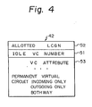
- Figure 4 is a view showing an example of the construction of a logical channel management memory 42 of each terminal adapter.
- the aforementioned first memory area in the memory 42 is shown by reference numeral 51.
- Indication as to whether packet communication is possible is performed using the number of idle virtual circuits as a parameter. When the number of idle virtual circuits is not zero, packet communication is possible. Zero number of idle virtual circuits means all the LCN's for packet communication are being used. Note that each time a communication packet is received, the number of idle virtual circuits is reduced by 1 (-1). When one call is completed, it is increased by 1 (+1). The LCGN to be used is registered in the second memory area 52 in the memory 42.
- the number of idle virtual circuits in the LCGN is shown by the above-mentioned idle virtual circuit number memory area 51. Further, there is a third memory area 53 for showing the attributes of the virtual circuits of the LCGN.
- the attributes of the virtual circuits correspond to the LCN range of the CCITT recommendation X.25. For example, it is possible to define the following:
- FIG. 5 is a view illustrating an example of the construction of a logical channel management memory on the ISDN side.
- the LCGN area 31 of Fig. 2 is comprised of the LCGN-0 to LCGN-15, each of which is provided with an area showing the virtual circuit attributes, an LCN busy/idle flag area, and an address area.
- the LCN busy/idle flag area has a number of flags showing the busy or idle state of the LCN's exactly corresponding to the number of LCN's.
- Each address area has written in it an address for accessing the logical channel memory at the right side of the figure.
- the logical channel memory is in the memory area (in the packet handler) and is a working area in which is registered control information required for actual call processing. Note that the control information is registered upon entry into the ISDN.
- Figure 6A is an arrow diagram showing the processing when originating a D-channel packet.
- Figure 6B is an arrow diagram showing the processing when terminating a D-channel packet.
- the three vertical lines indicate the data terminal equipment (DTE), terminal adapter (TA), and ISDN, respectively.
- the ISDN is, specifically, the packet handler.
- CR at the top left is a call request.
- the terminal adapter updates the logical channel management memory. That is, it reduces the number of idle virtual circuits (number of available virtual circuits) by 1. Subsequently, it notifies the call request (CR) to the packet handler in the ISDN.
- the packet handler checks the logical channel management memory 31 (Fig. 5) to confirm if there is an available logical channel and notifies the call termination (CN) through the terminal adapter to the data terminal equipment. At this time, the packet handler updates the busy/idle flag in the memory 31. Therefore, the data terminal equipment can originate a packet.
- the packet handler of the ISDN upon termination of the D-channel, the packet handler of the ISDN first starts the call offering procedure (CCITT recommendation X.31).
- the message at that time is UI [SET UP].
- UI is an unnumbered information frame at layer 2 (CCITT Q.932).
- I is an information frame at layer 2 (CCITT Q.921).
- the packet handler checks the logical channel management memory 31, selects an idle LCN, and rewrites a corresponding bit in the busy/idle flag as busy.
- an I [CONNECT ACK] message (ACK: acknowledge) is returned to the terminal adapter.
- the terminal adapter further waits for the CN packet to be transmitted.
- I'[CN]' is transmitted from the packet handler.
- the apostrophe is given since a previous procedure corresponded to layer 3 of the ISDN (CCITT Q.931) and now layer 3 of the packet (CCITT X.25) is being shifted to.
- the terminal adapter updates the memory 42. That is, it reduces the number of idle virtual circuits (number of available virtual circuits) by 1.
- FIG. 7 is a view illustrating an example of the format of a connect (LCGN) message in Fig. 6B.
- LCGN connect
- Figure 8 is a flow chart of the termination processing performed by the packet handler in the ISDN. Note that the "no" route in the second step is normally almost never activated, since this check must have already be done at terminal side.
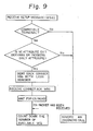
- Figure 9 is a flow chart for termination processing performed by the terminal adapter. When there is no terminal (compatible terminal) which can receive a terminated call or when the virtual circuit attributes are not suitable, the incoming call is neglected.
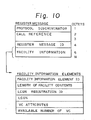
- Figure 10 is a view showing an example of the format of a registration message.
- the elements of the facility information in the message are shown in greater detail.
- Especially important among the facility information elements are the LCGN allotted to the newly established data terminal equipment, the virtual circuit attributes, and the number of available virtual circuits.
- FIG 11 is an arrow diagram showing an example of the registration procedure.
- FAC means facility information elements
- DISP display information elements
- INFO information message e.g., INFO information message
- RELEASE COM release complete message e.g., RELEASE COM release complete message
- Figure 12 is a flow chart showing the processing in the terminal adapter in the registration. As shown in the figure, the terminal adapter sends the LCGN information to the packet handler, receives an "accept" signal from the packet handler, then completes the contents of the memory 42 in it (Fig. 4).
- Figure 13 is a flow chart showing the processing in a packet handler in registration.
- packet handler confirms that there is space in the logical channel management memory 31 (Fig. 5), then newly allocates a busy/idle flag in the memory 31, and initializes the content of the said busy/idle flag. Later, it sends back an "accept" signal to the newly established data terminal equipment.
- the registration procedure ends and the newly established data terminal equipment is substantially activated.
Abstract
Description
- The present invention relates to a packet service in an integrated service digital network (ISDN), more particularly, to a method for management of logical channels for a packet service.
- An ISDN is meant to integrate all existing services on packet networks, telephone networks, and telex networks into a single whole. Various studies are underway on realization of such a network. Among these, the present invention refers in particular to a D-channel and/or B-channel packet handling method in ISDN. At the present time, a packet handler is used for packet processing interworking with main exchange via the common channel signaling method.
- Various questions arise when considering how to completely integrate packet switching service in an ISDN. Among these, the present invention takes up as one of its topics the provision of a number of pieces of data terminal equipment (DTE) at each subscriber access interface.
- When seen from an exchange, logical channel number areas (LCN) are managed for each subscriber independently. That is, in the ISDN, LCN's are allotted in correspondence to the subscribers, e.g., 10 LCN's for one subscriber and 15 LCN's for another. The exchange side does not maintain information on how many LCN's are allotted to individual pieces of data terminal equipment in the case of each subscriber being provided with a number of pieces of data terminal equipment. The omission by the exchange side of such management of characteristics of individual terminals is approved in CCITT recommendations. The exchange side need not know what the terminal equipment on the subscriber side is comprised of. In the final analysis, it is impossible to separately define logical channels for each data terminal equipment and impossible to allot the optimal number of LCN's for each data terminal equipment under the same access interface. This is disadvantageous when shifting to a full-scale ISDN and when the pieces of data terminal equipment of each subscriber become increasingly complicated.
- Further, each data terminal equipment must have the same number of LCN's and the "logical channel range" as spoken of in the CCITT recommendation X.25 for determining methods of use of LCN's must also be the same.
- The present invention was made to resolve the above-mentioned problems and has as its object the provision of a method for management of logical channels for a packet service free from the restrictions of the above-mentioned conditions and separate allotment of LCN's for each of a number of pieces of data terminal equipment of each subscriber and further the provision of a method for management of logical channels for an ISDN packet service wherein the ISDN side and terminal side can both be realized by just the some slight design modifications to current constructions.
- To achieve the above-mentioned object, the present invention allots an LCGN in the ISDN in advance for each piece of data terminal equipment. When there is a termination at said data terminal equipment, the data terminal equipment notifies the ISDN of the LCGN, whereby the packet can be received. This in turn enables the ISDN to offer a packet communication service without separate management of each piece of data terminal equipment at each subscriber side. Note that the data terminal equipment in the present invention is a packet mode terminal, that is, a computerized terminal under the CCITT X.25 which can handle a plurality of virtual circuits (VC). This packet mode terminal is connected to ISDN through a terminal adapter (TA).
- The above object and features of the present invention will be more apparent from the following description of the preferred embodiments with reference to the accompanying drawings, wherein:
- Fig. 1 is a view illustrating an example of an ISDN to which the present invention is applied;
- Fig. 2 is a view illustrating a specific example of a known construction of a logical channel;
- Fig. 3 is a view explaining the principle of the process of the present invention;
- Fig. 4 is a view illustrating an example of the construction of a logical
channel management memory 42 for each terminal adapter; - Fig. 5 is a view illustrating an example of the construction of a logical channel management memory on the ISDN side;
- Fig. 6A is an arrow diagram showing the processing when originating a D-channel packet;
- Fig. 6B is an arrow diagram showing the processing when terminating a D-channel packet;
- Fig. 7 is a view illustrating an example of the format of a connect (LCGN) message in Fig. 6B;
- Fig. 8 is a flow chart of the termination processing performed by the packet handler in the ISDN;
- Fig. 9 is a flow chart for termination processing performed by a terminal adapter;
- Fig. 10 is a view illustrating an example of the format of a registration message;
- Fig. 11 is an arrow diagram showing an example of the automatic registration procedures;
- Fig. 12 is a flow chart showing the processing in a terminal adapter in automatic registration; and
- Fig. 13 is a flow chart showing the processing in a packet handler in automatic registration.
- Before describing the embodiments of the present invention, the related art and the disadvantages therein will be described with reference to the related figures.
- Figure 1 is a view showing an example of an ISDN to which the present invention is applied. In the figure, the left side section set apart by the dotted line Q represents the data
terminal equipment side 11, i.e., the subscriber side, and the right side theISDN side 12. The dataterminal equipment side 11 and ISDNside 12 are connected bysubscriber lines 13. In the middle of thesubscriber lines 13 are inserted network termination units (NT) 14, which terminate the physical layer of the subscriber lines. Each subscriber is provided with a plurality of pieces of dataterminal equipment 15. - On the other side, the ISDN
side 12 is provided with, mainly, an exchange (EX) 21 and packet handler (PH) 22. The PH performs the interwork with the packet network. Theexchange 21 is, for example, comprised of digital line cards (DLC) 24 which terminate the digital lines, a frame multiplexer (FMX) 25 which receives D-channel information from the DLC's 24, determines whichpermanent path 23 should be used for thepacket handler 22, and performs frame multiplexing on the packet information for the path decided on, a line concentrator time switch (LTSW) which receives as input the D-channel information from theFMX 25 and B-channel information from the DLC's 24 and switches each, and a central processing unit (CPU) 27 which executes the ISDN protocol and controls the FMX together with a main memory (MEM) 28. Since it is assumed that each piece of data terminal equipment is an existing packet terminal, it is necessary to modify the protocol for the ISDN and therefore a terminal adapter (TA) 29 is provided. However, logical channels are important means for packet communication service, with a logical channel allotted to each of the permanent virtual circuits or the logical channels dynamically allotted like virtual calls. The main memory (MEM) 28 is used to reserve various call control information related to B-channel switching and D-channel permanent path. - Figure 2 shows a specific example of a known construction of logical channels, comprised of a maximum 16 (LCGN-0 to LCGN-15) number of logical channel group number (LCGN)
areas 31. EachLCGN area 31 consists of a maximum 256 number of LCN's 32 and therefore each subscriber can use logically the total 4096 (256 × 16) LCN's as desired. - As mentioned above, when seen from the
exchange 21, the LCN's are managed for eachsubscriber 13. That is, in the ISDN, LCN's are allotted in correspondence to the subscribers, e.g., 10 LCN's for a subscriber S1 and 15 LCN's for a subscriber S2. The exchange side does not maintain information on how many LCN's are allotted to individual pieces of data terminal equipment in the case of each subscriber being provided with a number of pieces of data terminal equipment. Thus, as mentioned above, the exchange side need not know what the terminal equipment on the subscriber side is comprised of. In the final analysis, it is impossible to separately define logical channels for each data terminal equipment and impossible to allot the optimal number of LCN's for each data terminal equipment. This is disadvantageous when shifting to a full-scale ISDN and when the pieces of data terminal equipment of each subscriber become increasingly complicated. Further, as mentioned above, each data terminal equipment must have the same number of LCN's and the "logical channel range" as spoken of in the CCITT recommendation X.25 for determining methods of use of LCN's must also be the same. - Figure 3 is a view for explaining the principle of the method according to the present invention. In the figure, each
subscriber 41 is provided with a logicalchannel management memory 42 for each terminal adapter. It defines the LCGN areas 31 (Fig. 2) used by the correspondingdata terminal equipment 15 to avoid coincidence of the same, registers this in thememory 42, and registers the number of idle virtual circuits in the LCGN area in thememory 42. The defined LCGN and the number of LCN's used are notified in advance when a subscriber enters the ISDN and a corresponding area is secured in the ISDN logical channel management memory. - On the other hand, when there is a request for termination in one piece of data terminal equipment at the subscriber, the subscriber side notifies the ISDN side of the LCGN which said data terminal equipment uses in accordance with the contents of the
memory 42. - The ISDN side, as mentioned above, does not have to be aware of each of the pieces of data terminal equipment in the subscribers and need only, at the time of entry, secure in the ISDN enough area for the LCGN for which use is desired and enough area for the necessary number of LCN's.
- For call origination of a data terminal equipment, the subscriber notifies the ISDN side of the LCGN which the data terminal equipment is using and then uses the LCGN. Conversely, in a request, for termination at a data terminal equipment, since the ISDN side cannot recognize the LCGN which the data terminal equipment uses, the subscriber notifies the ISDN side of the LCGN used, whereupon the ISDN sets an idle LCN in the LCGN area and starts the packet communication. At this time, the content of a first memory area in the
memory 42 in the terminal adapter is viewed to confirm that packet communication is now possible and then the termination packet is received. - Therefore, the work at the terminal adapter consists solely of notification of the LCGN to the ISDN side and updating of the contents of the first memory area in the
memory 42. Achievement of the object of the present invention does not place that much of a load on the terminal adapter. That is, the terminal adapter does not completely terminate the packet layer, but just manages the memory area. When there is a termination request, just the first memory area is viewed, a judgment made on whether termination is possible, and a response made to the ISDN side with corresponding LCGN defined in thesecond memory area 52 in thememory 42. Further, since thememory 42 is provided to define the LCGN at the subscriber, no burden is placed on the ISDN either. - Figure 4 is a view showing an example of the construction of a logical
channel management memory 42 of each terminal adapter. In the figure, the aforementioned first memory area in thememory 42 is shown byreference numeral 51. Indication as to whether packet communication is possible is performed using the number of idle virtual circuits as a parameter. When the number of idle virtual circuits is not zero, packet communication is possible. Zero number of idle virtual circuits means all the LCN's for packet communication are being used. Note that each time a communication packet is received, the number of idle virtual circuits is reduced by 1 (-1). When one call is completed, it is increased by 1 (+1). The LCGN to be used is registered in thesecond memory area 52 in thememory 42. The number of idle virtual circuits in the LCGN is shown by the above-mentioned idle virtual circuitnumber memory area 51. Further, there is athird memory area 53 for showing the attributes of the virtual circuits of the LCGN. The attributes of the virtual circuits correspond to the LCN range of the CCITT recommendation X.25. For example, it is possible to define the following: - 1) All LCN's in the LCGN are permanent virtual circuits.
- 2) All in the LCGN are exclusively for incoming calls.
- 3) All in the LCGN are for two-way communications.
- 4) All in the LCGN are exclusively for outgoing calls.
- Figure 5 is a view illustrating an example of the construction of a logical channel management memory on the ISDN side. The
LCGN area 31 of Fig. 2 is comprised of the LCGN-0 to LCGN-15, each of which is provided with an area showing the virtual circuit attributes, an LCN busy/idle flag area, and an address area. The LCN busy/idle flag area has a number of flags showing the busy or idle state of the LCN's exactly corresponding to the number of LCN's. Each address area has written in it an address for accessing the logical channel memory at the right side of the figure. The logical channel memory is in the memory area (in the packet handler) and is a working area in which is registered control information required for actual call processing. Note that the control information is registered upon entry into the ISDN. - Figure 6A is an arrow diagram showing the processing when originating a D-channel packet. Figure 6B is an arrow diagram showing the processing when terminating a D-channel packet. In Fig. 6A, the three vertical lines indicate the data terminal equipment (DTE), terminal adapter (TA), and ISDN, respectively. The ISDN is, specifically, the packet handler. In the figure, CR at the top left is a call request. The data terminal equipment is allotted, for example, "LCGN = i". The terminal adapter updates the logical channel management memory. That is, it reduces the number of idle virtual circuits (number of available virtual circuits) by 1. Subsequently, it notifies the call request (CR) to the packet handler in the ISDN.
- The packet handler checks the logical channel management memory 31 (Fig. 5) to confirm if there is an available logical channel and notifies the call termination (CN) through the terminal adapter to the data terminal equipment. At this time, the packet handler updates the busy/idle flag in the
memory 31. Therefore, the data terminal equipment can originate a packet. - In Fig. 6B, upon termination of the D-channel, the packet handler of the ISDN first starts the call offering procedure (CCITT recommendation X.31). The message at that time is UI [SET UP]. UI is an unnumbered information frame at layer 2 (CCITT Q.932). Receiving UI, the terminal adapter returns I [CONNECT (LCGN = i)] to the packet handler. I is an information frame at layer 2 (CCITT Q.921). One of the characteristics of the present invention is the insertion of this LCGN = i. The packet handler checks the logical
channel management memory 31, selects an idle LCN, and rewrites a corresponding bit in the busy/idle flag as busy. Using the selected LCN, an I [CONNECT ACK] message (ACK: acknowledge) is returned to the terminal adapter. The terminal adapter further waits for the CN packet to be transmitted. Finally, I'[CN]' is transmitted from the packet handler. The apostrophe is given since a previous procedure corresponded tolayer 3 of the ISDN (CCITT Q.931) and nowlayer 3 of the packet (CCITT X.25) is being shifted to. Receiving the I'[CN]' message, the terminal adapter updates thememory 42. That is, it reduces the number of idle virtual circuits (number of available virtual circuits) by 1. - Figure 7 is a view illustrating an example of the format of a connect (LCGN) message in Fig. 6B. In the facility information in the figure is accommodated LCGN information which is returned to the packet handler, a characteristic of the present invention.
- Figure 8 is a flow chart of the termination processing performed by the packet handler in the ISDN. Note that the "no" route in the second step is normally almost never activated, since this check must have already be done at terminal side.
- Figure 9 is a flow chart for termination processing performed by the terminal adapter. When there is no terminal (compatible terminal) which can receive a terminated call or when the virtual circuit attributes are not suitable, the incoming call is neglected.
- Returning to Fig. 3, exchange of a registration message (solid line) is newly performed between the
subscriber 41 and theISDN 12. In the working of the present invention, in the ISDN, it is essential that there be an accurate logicalchannel management memory 31 in each subscriber. Therefore, when a data terminal equipment is newly installed in some subscriber, the characteristics of the newly established data terminal equipment must be registered in the ISDN. Clearly, it would be very convenient if this registration could be directly performed by user. Therefore, a technique for direct registration is proposed. - Figure 10 is a view showing an example of the format of a registration message. The elements of the facility information in the message are shown in greater detail. Especially important among the facility information elements are the LCGN allotted to the newly established data terminal equipment, the virtual circuit attributes, and the number of available virtual circuits.
- Figure 11 is an arrow diagram showing an example of the registration procedure. The meaning of the abbreviations in the figure are as follows: FAC means facility information elements, DISP display information elements, INFO information message, and RELEASE COM release complete message.
- Figure 12 is a flow chart showing the processing in the terminal adapter in the registration. As shown in the figure, the terminal adapter sends the LCGN information to the packet handler, receives an "accept" signal from the packet handler, then completes the contents of the
memory 42 in it (Fig. 4). - Figure 13 is a flow chart showing the processing in a packet handler in registration. As shown in the figure, packet handler confirms that there is space in the logical channel management memory 31 (Fig. 5), then newly allocates a busy/idle flag in the
memory 31, and initializes the content of the said busy/idle flag. Later, it sends back an "accept" signal to the newly established data terminal equipment. Here, the registration procedure ends and the newly established data terminal equipment is substantially activated. - As explained above, according to the present invention, it is possible to manage logical channels separately, even to each of the plurality of pieces of data terminal equipment connected to the subscribers, without any major design modifications on either the terminal adapter side or ISDN side.
Claims (14)
said method for management of logical channels for ISDN packet service characterized in that said ISDN is completely unaware of details of the said number of pieces of data terminal equipment in the above subscribers and said ISDN forms logical channel management memories of a number corresponding exactly to the subscribers so as to simplify the logical channel management by the ISDN.
in which case the registration can be performed directly with the ISDN by the data terminal equipment through the subscriber line.
Applications Claiming Priority (2)
| Application Number | Priority Date | Filing Date | Title |
|---|---|---|---|
| JP45167/87 | 1987-03-02 | ||
| JP62045167A JPS63214043A (en) | 1987-03-02 | 1987-03-02 | Packet communication service system |
Publications (3)
| Publication Number | Publication Date |
|---|---|
| EP0281099A2 true EP0281099A2 (en) | 1988-09-07 |
| EP0281099A3 EP0281099A3 (en) | 1990-12-27 |
| EP0281099B1 EP0281099B1 (en) | 1994-06-15 |
Family
ID=12711707
Family Applications (1)
| Application Number | Title | Priority Date | Filing Date |
|---|---|---|---|
| EP88103165A Expired - Lifetime EP0281099B1 (en) | 1987-03-02 | 1988-03-02 | Method for managing logical channels for ISDN packet service |
Country Status (5)
| Country | Link |
|---|---|
| US (1) | US4878216A (en) |
| EP (1) | EP0281099B1 (en) |
| JP (1) | JPS63214043A (en) |
| CA (1) | CA1287390C (en) |
| DE (1) | DE3850145T2 (en) |
Cited By (3)
| Publication number | Priority date | Publication date | Assignee | Title |
|---|---|---|---|---|
| EP0408061A2 (en) * | 1989-07-14 | 1991-01-16 | Hitachi, Ltd. | Packet concentrator and packet switching system |
| US5537401A (en) * | 1990-11-30 | 1996-07-16 | Hitachi, Ltd. | System for and method of exchanging server data in packet unit |
| EP1079572A1 (en) * | 1999-08-26 | 2001-02-28 | Alcatel | Method for the establishment of a packet call |
Families Citing this family (42)
| Publication number | Priority date | Publication date | Assignee | Title |
|---|---|---|---|---|
| JPH01168155A (en) * | 1987-12-24 | 1989-07-03 | Canon Inc | Communication terminal set |
| JP2816164B2 (en) * | 1988-11-11 | 1998-10-27 | 株式会社日立製作所 | Communications system |
| US5276687A (en) * | 1989-04-14 | 1994-01-04 | Fujitsu Limited | Network system having different attributes of terminal equipment devices |
| US5051982A (en) * | 1989-07-27 | 1991-09-24 | Data General Corporation | Methods and apparatus for implementing switched virtual connections (SVCs) in a digital communications switching system |
| JPH0388534A (en) * | 1989-08-31 | 1991-04-12 | Hitachi Ltd | Packet switching system |
| JP2526695B2 (en) * | 1990-03-22 | 1996-08-21 | 日本電気株式会社 | Online information processing device |
| DE69118115T2 (en) * | 1990-11-15 | 1996-08-29 | At & T Corp | Device and method for validating credit cards in an ISDN network |
| US5159594A (en) * | 1990-12-31 | 1992-10-27 | At&T Bell Laboratories | Transparent communication of control information through a switching network |
| CA2109836C (en) * | 1991-05-23 | 2000-10-17 | Cheng-Hsu Ko | Dynamic channel allocation method and system for integrated services digital network |
| US5644712A (en) * | 1991-06-05 | 1997-07-01 | International Business Machines Corporation | Indirect addressing of channels via logical channel groups |
| US5390242A (en) * | 1991-12-30 | 1995-02-14 | At&T Corp. | Rerouting in a distributed telecommunication system |
| US5386466A (en) * | 1991-12-30 | 1995-01-31 | At&T Corp. | Automatic initialization of a distributed telecommunication system |
| US5377262A (en) * | 1991-12-30 | 1994-12-27 | At&T Corp. | Telecommunication switching system having adaptive routing switching nodes |
| US5416834A (en) * | 1991-12-30 | 1995-05-16 | At&T Corp. | Redirection of calls by a communication terminal |
| US5375167A (en) * | 1991-12-30 | 1994-12-20 | At&T Corp. | Telecommunication switching system having distributed dialing plan hierarchy |
| US5276679A (en) * | 1992-02-12 | 1994-01-04 | U.S. West Advanced Technologies, Inc. | Method for maintaining channels and a subscriber station for use in an ISDN system |
| JPH0653793U (en) * | 1992-09-19 | 1994-07-22 | 樫山工業株式会社 | Exhaust system equipment for semiconductor manufacturing |
| US5335229A (en) * | 1992-12-14 | 1994-08-02 | At&T Bell Laboratories | Logical integration of multiple network elements in a telecommunications management network |
| CA2107757C (en) * | 1992-12-18 | 1998-07-07 | Bruce Merrill Bales | Telecommunication switching system having transparent wireless features |
| US5390241A (en) * | 1992-12-18 | 1995-02-14 | At&T Corp. | Shared line appearance across a plurality of switching systems |
| US6181679B1 (en) * | 1993-03-19 | 2001-01-30 | International Business Machines Corporation | Management of packet transmission networks |
| US5502757A (en) * | 1993-12-22 | 1996-03-26 | At&T Corp. | Location dependent service for a wireless telephone |
| US5857075A (en) * | 1995-01-11 | 1999-01-05 | Sony Corporation | Method and integrated circuit for high-bandwidth network server interfacing to a local area network |
| US5764895A (en) * | 1995-01-11 | 1998-06-09 | Sony Corporation | Method and apparatus for directing data packets in a local area network device having a plurality of ports interconnected by a high-speed communication bus |
| US6256313B1 (en) | 1995-01-11 | 2001-07-03 | Sony Corporation | Triplet architecture in a multi-port bridge for a local area network |
| US5940597A (en) * | 1995-01-11 | 1999-08-17 | Sony Corporation | Method and apparatus for periodically updating entries in a content addressable memory |
| US5884040A (en) * | 1995-01-11 | 1999-03-16 | Sony Corporation | Per-packet jamming in a multi-port bridge for a local area network |
| US5659542A (en) | 1995-03-03 | 1997-08-19 | Intecom, Inc. | System and method for signalling and call processing for private and hybrid communications systems including multimedia systems |
| US6002667A (en) * | 1995-07-19 | 1999-12-14 | Fujitsu Network Communications, Inc. | Minimum guaranteed cell rate method and apparatus |
| JPH11512583A (en) * | 1995-09-14 | 1999-10-26 | フジツウ ネットワーク コミュニケーションズ,インコーポレイテッド | Transmitter-controlled flow control for buffer allocation in a wide area ATM network |
| AU1697697A (en) * | 1996-01-16 | 1997-08-11 | Fujitsu Limited | A reliable and flexible multicast mechanism for atm networks |
| US5748905A (en) * | 1996-08-30 | 1998-05-05 | Fujitsu Network Communications, Inc. | Frame classification using classification keys |
| US6363067B1 (en) | 1997-09-17 | 2002-03-26 | Sony Corporation | Staged partitioned communication bus for a multi-port bridge for a local area network |
| US6442168B1 (en) | 1997-09-17 | 2002-08-27 | Sony Corporation | High speed bus structure in a multi-port bridge for a local area network |
| US6308218B1 (en) | 1997-09-17 | 2001-10-23 | Sony Corporation | Address look-up mechanism in a multi-port bridge for a local area network |
| US6301256B1 (en) | 1997-09-17 | 2001-10-09 | Sony Corporation | Selection technique for preventing a source port from becoming a destination port in a multi-port bridge for a local area network |
| US6617879B1 (en) | 1997-09-17 | 2003-09-09 | Sony Corporation | Transparently partitioned communication bus for multi-port bridge for a local area network |
| US6816490B1 (en) | 1997-09-17 | 2004-11-09 | Sony Corporation | Statistical learning technique in a multi-port bridge for a local area network |
| US6157951A (en) * | 1997-09-17 | 2000-12-05 | Sony Corporation | Dual priority chains for data-communication ports in a multi-port bridge for a local area network |
| US6614810B1 (en) * | 1998-09-14 | 2003-09-02 | Samsung Electronics Co., Ltd. | Method for processing data to be transmitted over common channel |
| CN100466659C (en) * | 2004-07-13 | 2009-03-04 | 华为技术有限公司 | A method for automatic configuration of terminal equipment |
| US20090041460A1 (en) * | 2007-08-10 | 2009-02-12 | Bernard Marc R | Method and apparatus to provide bonded optical network devices |
Citations (3)
| Publication number | Priority date | Publication date | Assignee | Title |
|---|---|---|---|---|
| DE3210462A1 (en) * | 1982-03-22 | 1983-09-29 | Siemens AG, 1000 Berlin und 8000 München | Circuit arrangement for transmission of data signal packets between subscriber stations and a packet switching exchange |
| WO1985005237A1 (en) * | 1984-05-03 | 1985-11-21 | American Telephone & Telegraph Company | Distributed packet switching arrangement |
| JPS61227448A (en) * | 1985-04-02 | 1986-10-09 | Fujitsu Ltd | Terminal adaptor |
Family Cites Families (3)
| Publication number | Priority date | Publication date | Assignee | Title |
|---|---|---|---|---|
| US4688214A (en) * | 1986-03-12 | 1987-08-18 | American Telephone And Telegraph Company, At&T Laboratories | Switching system control arrangements |
| US4720850A (en) * | 1986-03-14 | 1988-01-19 | American Telephone And Telegraph Company At&T Bell Laboratories | Communication system control arrangement |
| US4713806A (en) * | 1986-03-14 | 1987-12-15 | American Telephone And Telegraph Company, At&T Bell Laboratories | Communication system control arrangement |
-
1987
- 1987-03-02 JP JP62045167A patent/JPS63214043A/en active Granted
-
1988
- 1988-03-01 CA CA000560238A patent/CA1287390C/en not_active Expired - Lifetime
- 1988-03-02 DE DE3850145T patent/DE3850145T2/en not_active Expired - Fee Related
- 1988-03-02 EP EP88103165A patent/EP0281099B1/en not_active Expired - Lifetime
- 1988-03-02 US US07/163,096 patent/US4878216A/en not_active Expired - Fee Related
Patent Citations (3)
| Publication number | Priority date | Publication date | Assignee | Title |
|---|---|---|---|---|
| DE3210462A1 (en) * | 1982-03-22 | 1983-09-29 | Siemens AG, 1000 Berlin und 8000 München | Circuit arrangement for transmission of data signal packets between subscriber stations and a packet switching exchange |
| WO1985005237A1 (en) * | 1984-05-03 | 1985-11-21 | American Telephone & Telegraph Company | Distributed packet switching arrangement |
| JPS61227448A (en) * | 1985-04-02 | 1986-10-09 | Fujitsu Ltd | Terminal adaptor |
Non-Patent Citations (3)
| Title |
|---|
| NTG-FACHBERICHTE - VORTR[GE DER NTG-FACHTAGUNG, Berlin, 25th - 27th March 1985, pages 112-119; W. KOENIG et al.: "D-Kanal-Protokoll im ISDN-Pilotprojekt" * |
| PATENT ABSTRACTS OF JAPAN, vol. 11, no. 70 (E-485)[2517], 3rd March 1987; & JP-A-61 227 448 (FUJITSU LTD) 09-10-1986 (Cat. A) * |
| PROCEEDINGS OF THE 7TH INTERNATIONAL CONFERENCE ON COMPUTER COMMUNICATION, Sydney, 30th October - 2nd November 1984, pages 114-119; M.S. UNSOY et al.: "Interworking of telephone & packet switched data networks" * |
Cited By (9)
| Publication number | Priority date | Publication date | Assignee | Title |
|---|---|---|---|---|
| EP0408061A2 (en) * | 1989-07-14 | 1991-01-16 | Hitachi, Ltd. | Packet concentrator and packet switching system |
| EP0408061A3 (en) * | 1989-07-14 | 1992-12-23 | Hitachi, Ltd. | Packet concentrator and packet switching system |
| US5537401A (en) * | 1990-11-30 | 1996-07-16 | Hitachi, Ltd. | System for and method of exchanging server data in packet unit |
| US6141338A (en) * | 1990-11-30 | 2000-10-31 | Hitachi, Ltd. | System for and method of exchanging server data in packet unit |
| US6621816B1 (en) | 1990-11-30 | 2003-09-16 | Hitachi, Ltd. | System for and method of exchanging server data in packet unit |
| US7006496B2 (en) | 1990-11-30 | 2006-02-28 | Hitachi, Ltd. | System for and method of exchanging server data in packet unit |
| US7236487B2 (en) | 1990-11-30 | 2007-06-26 | Hitachi, Ltd. | System for and method of exchanging server data in packet unit |
| EP1079572A1 (en) * | 1999-08-26 | 2001-02-28 | Alcatel | Method for the establishment of a packet call |
| FR2798029A1 (en) * | 1999-08-26 | 2001-03-02 | Cit Alcatel | METHOD FOR ESTABLISHING A PACKET COMMUNICATION |
Also Published As
| Publication number | Publication date |
|---|---|
| JPH0573300B2 (en) | 1993-10-14 |
| EP0281099A3 (en) | 1990-12-27 |
| CA1287390C (en) | 1991-08-06 |
| JPS63214043A (en) | 1988-09-06 |
| DE3850145D1 (en) | 1994-07-21 |
| DE3850145T2 (en) | 1994-11-10 |
| US4878216A (en) | 1989-10-31 |
| EP0281099B1 (en) | 1994-06-15 |
Similar Documents
| Publication | Publication Date | Title |
|---|---|---|
| US4878216A (en) | Method for management of logical channels for ISDN packet service | |
| US4586134A (en) | Computer network system and its use for information unit transmission | |
| US5781623A (en) | Method of controlling an access network as well as exchange and access network | |
| EP0307401A1 (en) | Method and apparatus for providing variable reliability in a telecommunication switching system. | |
| JP3145284B2 (en) | Methods of handling telephone calls, providing telephone calls, and stopping telephone calls | |
| EP0594244B1 (en) | Communication system and a private branch exchange to be used in such a communication system | |
| WO1997035404A1 (en) | Method and arrangement relating to the installation of a new subscriber in a telecomunications network | |
| US20010053219A1 (en) | Method of establishing a connection, as well as exchange, service computer and communications network | |
| JPH118694A (en) | Exchange having virtual access network function and exchange system | |
| US6765886B1 (en) | Call set-up and service invocation in telecommunications networks | |
| CA2250327A1 (en) | System and method for providing services to subscriber stations connected to an access network | |
| JP3081012B2 (en) | Equipment in the subscriber area of an integrated services digital communication network. | |
| JP3033668B2 (en) | Calling / receiving method for ISDN multi-line line of exchange or key telephone | |
| KR100237480B1 (en) | Method of deactivating the night service of the information desk in the digital switching system | |
| KR100237478B1 (en) | Method of activating the night service of the information desk in the digital switching system | |
| EP1006705A1 (en) | Private telecommunications switching system and method of establishing a connection | |
| JP2761880B2 (en) | Transmission control system for private branch exchange | |
| JP2616692B2 (en) | ISDN exchange | |
| KR100237481B1 (en) | Method of outputting informations about information desk belong to another group to one information desk in the digital switching system | |
| KR100237482B1 (en) | Method of changing status of the other information desks belong to the same group to one information desk in the digital switching system | |
| JPS6147477B2 (en) | ||
| KR100237479B1 (en) | Method of outputting call pick-up group's information to the information desk in the digital switching system | |
| JPH11234412A (en) | Private branch exchange system | |
| JPH06104987A (en) | Digital exchange | |
| NO986037L (en) | Signaling between an ISDN-connected device and a power plant |
Legal Events
| Date | Code | Title | Description |
|---|---|---|---|
| PUAI | Public reference made under article 153(3) epc to a published international application that has entered the european phase |
Free format text: ORIGINAL CODE: 0009012 |
|
| AK | Designated contracting states |
Kind code of ref document: A2 Designated state(s): DE FR GB SE |
|
| PUAL | Search report despatched |
Free format text: ORIGINAL CODE: 0009013 |
|
| AK | Designated contracting states |
Kind code of ref document: A3 Designated state(s): DE FR GB SE |
|
| 17P | Request for examination filed |
Effective date: 19901227 |
|
| 17Q | First examination report despatched |
Effective date: 19921119 |
|
| GRAA | (expected) grant |
Free format text: ORIGINAL CODE: 0009210 |
|
| AK | Designated contracting states |
Kind code of ref document: B1 Designated state(s): DE FR GB SE |
|
| REF | Corresponds to: |
Ref document number: 3850145 Country of ref document: DE Date of ref document: 19940721 |
|
| ET | Fr: translation filed | ||
| EAL | Se: european patent in force in sweden |
Ref document number: 88103165.2 |
|
| PLBE | No opposition filed within time limit |
Free format text: ORIGINAL CODE: 0009261 |
|
| STAA | Information on the status of an ep patent application or granted ep patent |
Free format text: STATUS: NO OPPOSITION FILED WITHIN TIME LIMIT |
|
| 26N | No opposition filed | ||
| PGFP | Annual fee paid to national office [announced via postgrant information from national office to epo] |
Ref country code: GB Payment date: 19990304 Year of fee payment: 12 |
|
| PGFP | Annual fee paid to national office [announced via postgrant information from national office to epo] |
Ref country code: SE Payment date: 19990305 Year of fee payment: 12 Ref country code: DE Payment date: 19990305 Year of fee payment: 12 |
|
| PGFP | Annual fee paid to national office [announced via postgrant information from national office to epo] |
Ref country code: FR Payment date: 19990309 Year of fee payment: 12 |
|
| PG25 | Lapsed in a contracting state [announced via postgrant information from national office to epo] |
Ref country code: GB Free format text: LAPSE BECAUSE OF NON-PAYMENT OF DUE FEES Effective date: 20000302 |
|
| PG25 | Lapsed in a contracting state [announced via postgrant information from national office to epo] |
Ref country code: SE Free format text: LAPSE BECAUSE OF NON-PAYMENT OF DUE FEES Effective date: 20000303 |
|
| GBPC | Gb: european patent ceased through non-payment of renewal fee |
Effective date: 20000302 |
|
| EUG | Se: european patent has lapsed |
Ref document number: 88103165.2 |
|
| PG25 | Lapsed in a contracting state [announced via postgrant information from national office to epo] |
Ref country code: FR Free format text: LAPSE BECAUSE OF NON-PAYMENT OF DUE FEES Effective date: 20001130 |
|
| REG | Reference to a national code |
Ref country code: FR Ref legal event code: ST |
|
| PG25 | Lapsed in a contracting state [announced via postgrant information from national office to epo] |
Ref country code: DE Free format text: LAPSE BECAUSE OF NON-PAYMENT OF DUE FEES Effective date: 20010103 |