EP0280965B1 - Probe-gripper for automated sample preparation system - Google Patents
Probe-gripper for automated sample preparation system Download PDFInfo
- Publication number
- EP0280965B1 EP0280965B1 EP88102385A EP88102385A EP0280965B1 EP 0280965 B1 EP0280965 B1 EP 0280965B1 EP 88102385 A EP88102385 A EP 88102385A EP 88102385 A EP88102385 A EP 88102385A EP 0280965 B1 EP0280965 B1 EP 0280965B1
- Authority
- EP
- European Patent Office
- Prior art keywords
- electrode
- probe
- gripper
- tube
- annular
- Prior art date
- Legal status (The legal status is an assumption and is not a legal conclusion. Google has not performed a legal analysis and makes no representation as to the accuracy of the status listed.)
- Expired
Links
Images

Classifications
-
- B—PERFORMING OPERATIONS; TRANSPORTING
- B01—PHYSICAL OR CHEMICAL PROCESSES OR APPARATUS IN GENERAL
- B01L—CHEMICAL OR PHYSICAL LABORATORY APPARATUS FOR GENERAL USE
- B01L9/00—Supporting devices; Holding devices
- B01L9/50—Clamping means, tongs
-
- B—PERFORMING OPERATIONS; TRANSPORTING
- B65—CONVEYING; PACKING; STORING; HANDLING THIN OR FILAMENTARY MATERIAL
- B65G—TRANSPORT OR STORAGE DEVICES, e.g. CONVEYORS FOR LOADING OR TIPPING, SHOP CONVEYOR SYSTEMS OR PNEUMATIC TUBE CONVEYORS
- B65G47/00—Article or material-handling devices associated with conveyors; Methods employing such devices
- B65G47/74—Feeding, transfer, or discharging devices of particular kinds or types
- B65G47/90—Devices for picking-up and depositing articles or materials
- B65G47/908—Devices for picking-up and depositing articles or materials with inflatable picking-up means
Definitions
- This invention relates generally to automated sample preparation systems, and more particularly to a probe-gripper for use with such systems.
- US-A-4 326 851 discloses an apparatus for determining when the bottom tip of a fluid aspirating probe touches or makes contact with the upper surface of a sample fluid contained in a supply cavity.
- a capacitor is formed, where one plate of which is an electrode biased against the bottom surface of a rotatable supply tray and positioned under an individual supply cavity the other plate of which is the bottom surface of the sample fluid contained in that individual cavity and whose dielectric is the material of the sample tray.
- the electrode has an AC signal applied thereto the modulation of which is sensed to determine when contact is made.
- the fluid probe is connected to the signal ground so that the AC signal on the electrode is capacitively ground when the probe touches the conductive fluid sample top surface. This modulates the AC signal which is sensed to provide the level sense signal.
- robots may be powered by pneumatic means, i.e. compressed air, or hydraulic means.
- FR-A-2 439 157 discloses a cylindrically shaped lifting device with ducts for a working fluid and a annular cavity is covered by an elastic sheathmember which is influtable by the working fluid flowing through the ducts to the annular cavity.
- conduits or probes through which fluid flows. They perform various operations such as, aspiration and despensing of fluid and pipetting.
- the probes move both horizontally and vertically generally in x, y and z axes in a predetermined pattern.
- their functions have been limited to merely the handling of fluids.
- Such probes generally speaking, are incapable of moving hardware, such as test tubes, filters, and various solid phase elements.
- independent gripping devices having independent transport mechanisms, are required to move the hardware independently of the probe relative to the three axes.
- Pressurized fluid such as air is conducted lengthwise of the probe in channels located between the sample tube and the electrode to an internal plenum, which, in turn, communicates with an exterior plenum located at the annular exterior of the electrode in the area of the free intermediate annular portion of the elastomeric member.
- the tube and the electrode are insulated, one from another, as are the exposed portions of the tube and the barrel which come in contact with liquids.
- the probe per se, is movable along x, y, and z axes by a robot, which in turn is controlled by a computer to perform the functions of aspiration and dispensing of fluids.
- the probe is moved to and from containers such as test tubes to perform functions of pipetting, flushing, and the like. Simultaneously its elastomeric member is expanded to grip the interior of test tubes, filters, and other hardware employed in sample preparation systems, and contracted to release them.
- a probe-gripper generally designated, 10, is shown in the drawings on a scale which is approximately 10 times larger than an actual probe- gripper made in accordance with the invention, it being understood that the probe-gripper is small enough to enter the open end of a conventional laboratory test tube.
- the probe-gripper includes a sample tube 12, extending lengthwise of the probe, and includes a central passageway 14, through which fluid may flow alternatively in opposite directions. Stainless steel has been found satisfactory for the tube.
- the sample tube includes a frustoconical nose 16, at one end, which may be either formed integral with the tube, or made separately and assembled on the tube, as for example, by the use of silver solder.
- the electrode is made of brass and includes an internal cylindrical plenum 20, which communicates with an external frustoconical plenum 22, by way of four passageways 24.
- the outer diameter of the tube 12 is cylindrical and the inner diameter of the electrode 18, is hexigonal. It may also assume any other polygonal shape.
- the inner diameter of the electrode 18, and the outer diameter of the tube 12, are insulated from each other by a nonconductive coating, as for example, teflon.
- the intermediate portion 42 of the elastomeric sheath surrounds the external plenum 22.
- the barrel 40 is made of stainless steel and is connected to ground by a conductor 44.
- the capacitance measuring means in the computer detects changes in capacitance below the electrode 18 and the barrel 40 incurring generally in the area designated area 46. For example, when the probe is at rest, in other words, not dipped in liquid or not engaging a piece of hardware, the capacitance of the area 46, would be determined by the dielectric value of the elastomeric member 30, and the surrounding air. This could be designated the zero point by the computer controlling the operation of the robot manipulated probe 10.
- the probe is shown inserted in the filter 50 with its elastomeric sheath engaging the interior wall 52 of the filter 50.
- the wall 52 is representative of a luer connector, or for that matter, the inner diameter of a test tube.
- pressurized air is caused to flow through the six passageways in the electrode 18 that surround the outer diameter of the tube 12, to the inner cylindrical plenum 20, through the radial passageways 24, to the exterior plenum 22, pressurizing it and causing the elastomeric sheath to bulge outwardly gripping the interior of the filter or other object it is intended to engage.
- the computer causes the robot to raise the gripper-probe 10 and to move it to any desired location.
- the filter if it is to be discarded, will drop from the gripper-probe when the plenum 22 is depressurized and the elastomeric sheath returns to its original position.
- probe-gripper is capable of many additional functions, as for example, to simultaneously energize a secondary gripping device through the sample tube 12 in order to transport test tubes or any other hardware.
Description
- This invention relates generally to automated sample preparation systems, and more particularly to a probe-gripper for use with such systems.
- There are many systems used for automated sample preparation, which perform fluid handling operations. These systems involve the flow and movement of liquids, as well as solid phase elements, sample holding containers, test tubes, filters, and the like.
- US-A-4 326 851 discloses an apparatus for determining when the bottom tip of a fluid aspirating probe touches or makes contact with the upper surface of a sample fluid contained in a supply cavity.
- According to this prior art, a capacitor is formed, where one plate of which is an electrode biased against the bottom surface of a rotatable supply tray and positioned under an individual supply cavity the other plate of which is the bottom surface of the sample fluid contained in that individual cavity and whose dielectric is the material of the sample tray. The electrode has an AC signal applied thereto the modulation of which is sensed to determine when contact is made. The fluid probe is connected to the signal ground so that the AC signal on the electrode is capacitively ground when the probe touches the conductive fluid sample top surface. This modulates the AC signal which is sensed to provide the level sense signal.
- Journal of Physics E, Scientific Instruments, vol.18, no.11, November 1985, pages 891-896, The Institute of Physics, Bristol, GB; J. Huddleston: "The use of small robots for laboratory manipulations", discloses the general hint that robots may be powered by pneumatic means, i.e. compressed air, or hydraulic means.
- Further, a variety of end affectors is discussed in this document. Expressed mentioned are two- or three-fingered grippers, vacuum grippers for objects with large radii, or strip materials, magnetic chucks, fork-shaped end effectors or a probe, dispenser, syringe, coater heater or detector required by a specific experiment.
- FR-A-2 439 157 discloses a cylindrically shaped lifting device with ducts for a working fluid and a annular cavity is covered by an elastic sheathmember which is influtable by the working fluid flowing through the ducts to the annular cavity.
- Some of these systems include conduits or probes through which fluid flows. They perform various operations such as, aspiration and despensing of fluid and pipetting. The probes move both horizontally and vertically generally in x, y and z axes in a predetermined pattern. However, their functions have been limited to merely the handling of fluids.
- Such probes, generally speaking, are incapable of moving hardware, such as test tubes, filters, and various solid phase elements. Thus, independent gripping devices having independent transport mechanisms, are required to move the hardware independently of the probe relative to the three axes.
- It is specifically an object of this invention to provide a probe-gripper, which can perform all of the fluid handling functions that prior probes performed, plus the functions of handling and transporting the hardware involved in the sample preparations systems.
- It is another object of this invention to provide a probe-gripper which has means for detecting whether or not it is in contact with fluid or a piece of hardware.
- There is provided a probe-gripper for automated sample preparation systems as claimed in claim 1.
- Pressurized fluid, such as air, is conducted lengthwise of the probe in channels located between the sample tube and the electrode to an internal plenum, which, in turn, communicates with an exterior plenum located at the annular exterior of the electrode in the area of the free intermediate annular portion of the elastomeric member.
- The tube and the electrode are insulated, one from another, as are the exposed portions of the tube and the barrel which come in contact with liquids.
- The probe, per se, is movable along x, y, and z axes by a robot, which in turn is controlled by a computer to perform the functions of aspiration and dispensing of fluids. The probe is moved to and from containers such as test tubes to perform functions of pipetting, flushing, and the like. Simultaneously its elastomeric member is expanded to grip the interior of test tubes, filters, and other hardware employed in sample preparation systems, and contracted to release them.
- The above and other features of the invention, including various novel details of construction and combinations of parts, will now be more particularly described with reference to the accompanying drawings and pointed out in the Claims. It will be understood that the particular probe-gripper embodying the invention, is shown by way of illustration only, and not as a limitation of the invention. The principles and features of this invention may be employed in varied and numerous embodiments without departing from the scope of the invention.
-
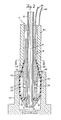
- Figure 1 is a sectional view of a probe-gripper embodying the features of the present invention.
- Figure 2 is a sectional view of the probe-gripper with its elastomeric member inflated to grip the interior of a filter.
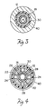
- Figure 3 is a section taken on the lines III III on Figure 2.
- Figure 4 is a section taken on lines IV IV on Figure 1.
- A probe-gripper generally designated, 10, is shown in the drawings on a scale which is approximately 10 times larger than an actual probe- gripper made in accordance with the invention, it being understood that the probe-gripper is small enough to enter the open end of a conventional laboratory test tube. The probe-gripper includes a
sample tube 12, extending lengthwise of the probe, and includes acentral passageway 14, through which fluid may flow alternatively in opposite directions. Stainless steel has been found satisfactory for the tube. The sample tube includes afrustoconical nose 16, at one end, which may be either formed integral with the tube, or made separately and assembled on the tube, as for example, by the use of silver solder. - An
annular electrode 18, surrounds the lower end of thetube 12, adjacent thenose 16. The electrode is made of brass and includes an internalcylindrical plenum 20, which communicates with an externalfrustoconical plenum 22, by way of fourpassageways 24. Awire 26, connects the electrode to capacitance measuring means, which may be part of the computer and not shown. - As will be seen in Figures 3 and 4, the outer diameter of the
tube 12, is cylindrical and the inner diameter of theelectrode 18, is hexigonal. It may also assume any other polygonal shape. Thus, when the electrode is assembled over the tube, there are 6, generallytriangular passageways 28 running parallel with the axis A of thetube 12 to permit pressurized fluid to flow to theinterior plenum 20, through thepassageways 24, to theexterior plenum 22. The inner diameter of theelectrode 18, and the outer diameter of thetube 12, are insulated from each other by a nonconductive coating, as for example, teflon. - An annular, elastomeric member in the form of a
sheath 30, surrounds theplenum 22, and includes a generally flat,bottom portion 32, which is clamped between theelectrode 18, and thenose 16 of thetube 12. An upper, generallyfrustoconical portion 34, is secured to theelectrode 18, being clamped to a conical surface 36, by aconical portion 38, of abarrel 40, which surrounds the upper portion of theelectrode 18, and consequently, thetube 12. Theintermediate portion 42 of the elastomeric sheath surrounds theexternal plenum 22. - The
barrel 40, is made of stainless steel and is connected to ground by aconductor 44. The capacitance measuring means in the computer, detects changes in capacitance below theelectrode 18 and thebarrel 40 incurring generally in the area designatedarea 46. For example, when the probe is at rest, in other words, not dipped in liquid or not engaging a piece of hardware, the capacitance of thearea 46, would be determined by the dielectric value of theelastomeric member 30, and the surrounding air. This could be designated the zero point by the computer controlling the operation of the robot manipulatedprobe 10. However, when the probe is caused to enter a test tube or other vessel containing a fluid, dielectric value of the fluid would cause the capacitance between theelectrode 18, and thesheath 40, to change, telling the computer that the probe had entered the fluid. In like manner, when the probe comes close to or enters a piece of hardware, as for example, afilter 50, illustrated in Figure 2, the capacitance would change to another value thereby indicating that the probe had done its work. - Referring now to Figure 2, the probe is shown inserted in the
filter 50 with its elastomeric sheath engaging the interior wall 52 of thefilter 50. The wall 52 is representative of a luer connector, or for that matter, the inner diameter of a test tube. When the probe has entered the open mouth of thefilter 50, pressurized air is caused to flow through the six passageways in theelectrode 18 that surround the outer diameter of thetube 12, to the innercylindrical plenum 20, through theradial passageways 24, to theexterior plenum 22, pressurizing it and causing the elastomeric sheath to bulge outwardly gripping the interior of the filter or other object it is intended to engage. Thereafter, the computer causes the robot to raise the gripper-probe 10 and to move it to any desired location. The filter, if it is to be discarded, will drop from the gripper-probe when theplenum 22 is depressurized and the elastomeric sheath returns to its original position. - It will be obvious that the probe-gripper is capable of many additional functions, as for example, to simultaneously energize a secondary gripping device through the
sample tube 12 in order to transport test tubes or any other hardware.
Claims (6)
- A probe-gripper (10) for automated sample preparation systems comprising:a. a sample tube (12) extending lengthwise of the probe through which fluid may flow, alternatively, in opposite directions,b. an annular electrode (18) surrounding the sample tube(12) adjacent one of its ends,c. a barrel (40) surrounding at least a portion of the electrode (18),d. means (26, 44) for connecting the barrel (40) and the electrode (18) to capacitance measuring means to detect changes in capacitance between them,e. an annular, elastomeric member (30) surrounding at least a portion of the electrode (18),f. opposite end portions (32, 38) of the annular, elastomeric member (30) being secured to the electrode (18),g. an intermediate annular portion (42) of the elastomeric member (30) being free from the electrode (18) to create an inflatable bladder, and,h. means (28) for conducting pressurized fluid lengthwise of the probe to the interior of the inflatable bladder (42) to cause it to expand and contract into gripping and releasing positions respectively.
- A probe-gripper (10) according to Claim 1 wherein, one end portion (32) of the annular, elastomeric member (30) is clamped between the electrode (18) and the barrel (40), the opposite end portion (38) of the annular elastomeric member (30) is clamped between the electrode (18) and an end portion (16) of the tube.
- A probe-gripper (10) according to Claims 1 or 2 wherein, at least one fluid passageway (24) extends between the tube (12) and the electrode and communicates with a plenum (20) between the electrode (18) and the interior of the inflatable bladder (42) to cause the bladder (42) to expand and contract when pressurized fluid is caused to enter the fluid passageway.
- A probe-gripper (10) according to Claim 1 wherein, the electrode (18) is brass and the barrel (40) is steel.
- A probe-gripper (10) according to Claim 1 wherein, the tube (12) is insulated from the electrode (18).
- A probe-gripper (10) according to Claim 1 wherein, the interior of the electrode (18) is polygonal in cross section and the exterior of the tube (12) is circular in cross section, the electrode (18) and tube (12) creating between them fluid passageways (28) thereby forming the means to conduct pressurized fluid to the bladder (42).
Applications Claiming Priority (2)
| Application Number | Priority Date | Filing Date | Title |
|---|---|---|---|
| US22269 | 1987-03-05 | ||
| US07/022,269 US4747316A (en) | 1987-03-05 | 1987-03-05 | Probe-gripper |
Publications (3)
| Publication Number | Publication Date |
|---|---|
| EP0280965A2 EP0280965A2 (en) | 1988-09-07 |
| EP0280965A3 EP0280965A3 (en) | 1989-02-22 |
| EP0280965B1 true EP0280965B1 (en) | 1992-05-13 |
Family
ID=21808731
Family Applications (1)
| Application Number | Title | Priority Date | Filing Date |
|---|---|---|---|
| EP88102385A Expired EP0280965B1 (en) | 1987-03-05 | 1988-02-18 | Probe-gripper for automated sample preparation system |
Country Status (4)
| Country | Link |
|---|---|
| US (1) | US4747316A (en) |
| EP (1) | EP0280965B1 (en) |
| JP (1) | JP2653665B2 (en) |
| DE (1) | DE3870927D1 (en) |
Families Citing this family (10)
| Publication number | Priority date | Publication date | Assignee | Title |
|---|---|---|---|---|
| US5215376A (en) * | 1989-09-08 | 1993-06-01 | Becton, Dickinson And Company | Method for causing vortices in a test tube |
| DE4203638A1 (en) * | 1992-02-08 | 1993-08-12 | Boehringer Mannheim Gmbh | LIQUID TRANSFER DEVICE FOR AN ANALYZER |
| GB9300200D0 (en) * | 1993-01-07 | 1993-03-03 | Unilever Plc | Article handling |
| US5372786A (en) * | 1993-07-02 | 1994-12-13 | Abbott Laboratories | Method of holding a sample container |
| JPH09127130A (en) * | 1995-08-31 | 1997-05-16 | Teruaki Ito | Nozzle device for pipetting and dispensing specimen |
| EP0913671A1 (en) * | 1997-10-29 | 1999-05-06 | Roche Diagnostics GmbH | Method and device for liquid transfer in an analyzer |
| DE19919305A1 (en) | 1999-04-28 | 2000-11-02 | Roche Diagnostics Gmbh | Method and device for liquid transfer with an analysis device |
| JP5883214B2 (en) * | 2010-05-25 | 2016-03-09 | 株式会社東芝 | Automatic analyzer |
| FI3626343T3 (en) * | 2018-09-18 | 2024-03-15 | Eppendorf Se | Holding device for holding a pipetting container on a pipetting device |
| CN114377734A (en) * | 2022-01-19 | 2022-04-22 | 重庆化工职业学院 | Household utensils cabinet for chemical industry experiments |
Family Cites Families (15)
| Publication number | Priority date | Publication date | Assignee | Title |
|---|---|---|---|---|
| US1195516A (en) * | 1916-08-22 | shields | ||
| US814169A (en) * | 1904-03-16 | 1906-03-06 | Filter & Brautechnische Maschinen Fabrik Act Ges | Apparatus for decanting liquids. |
| US2741381A (en) * | 1951-03-27 | 1956-04-10 | Colgate Palmolive Co | Transfer apparatus |
| US3103958A (en) * | 1961-03-23 | 1963-09-17 | Standard Oil Co | Liquid fill assembly |
| US3285299A (en) * | 1964-04-30 | 1966-11-15 | Nat Ind Products Company | Container sealing and filling means |
| DE1224539B (en) * | 1965-02-24 | 1966-09-08 | Rolf Huebner Dipl Ing | Device for taking gas samples, especially for underground spaces |
| US3352333A (en) * | 1965-03-31 | 1967-11-14 | Carrier Corp | Spray gun for cleaning tubes having radially expansible means for sealingly engagingsaid tube |
| FR2032002A5 (en) * | 1969-02-14 | 1970-11-20 | Applic Gaz Sa | |
| CH522270A (en) * | 1970-09-30 | 1972-06-15 | Bbc Brown Boveri & Cie | Gripping device for nuclear reactor loading machine |
| US3741409A (en) * | 1971-12-01 | 1973-06-26 | Freeport Brick Co | Transfer apparatus for articles with a vertical passage |
| US3945486A (en) * | 1974-10-15 | 1976-03-23 | Glass Containers Corporation | Container supporting and transporting device |
| US4273505A (en) * | 1978-09-22 | 1981-06-16 | The United States Of America As Represented By The Administrator Of The National Aeronautics And Space Administration | Pneumatic inflatable end effector |
| DE2845094A1 (en) * | 1978-10-17 | 1980-05-08 | Freudenberg Carl Fa | GRIP DEVICE |
| US4326851A (en) * | 1980-10-24 | 1982-04-27 | Coulter Electronics, Inc. | Level sensor apparatus and method |
| FI70328C (en) * | 1983-11-17 | 1986-09-15 | Tampella Oy Ab | FUNCTIONAL ANALYSIS FOR THE END OF ANALYSIS PROVIDING THE FRAMEWORK OF ANALYSIS |
-
1987
- 1987-03-05 US US07/022,269 patent/US4747316A/en not_active Expired - Lifetime
-
1988
- 1988-02-18 DE DE8888102385T patent/DE3870927D1/en not_active Expired - Lifetime
- 1988-02-18 EP EP88102385A patent/EP0280965B1/en not_active Expired
- 1988-03-04 JP JP63049932A patent/JP2653665B2/en not_active Expired - Lifetime
Also Published As
| Publication number | Publication date |
|---|---|
| JPH01235853A (en) | 1989-09-20 |
| JP2653665B2 (en) | 1997-09-17 |
| US4747316A (en) | 1988-05-31 |
| DE3870927D1 (en) | 1992-06-17 |
| EP0280965A2 (en) | 1988-09-07 |
| EP0280965A3 (en) | 1989-02-22 |
Similar Documents
| Publication | Publication Date | Title |
|---|---|---|
| EP0280965B1 (en) | Probe-gripper for automated sample preparation system | |
| EP1381495B1 (en) | Gripping mechanisms, apparatus, and methods | |
| US4841786A (en) | Specimen distributing system | |
| US6323035B1 (en) | Systems and methods for handling and manipulating multi-well plates | |
| US4799599A (en) | Specimen cup and cap assembly for clinical analyzer | |
| US5452619A (en) | Method for pipetting a blood sample | |
| US10981162B2 (en) | Pipetting device having a pipette tip detection unit and method for detecting a pipette tip on a pipetting device | |
| US5158748A (en) | Automated dispensing and diluting system | |
| CA2121499C (en) | Liquid aspirating method | |
| EP0341438A2 (en) | Pneumatic sensing system | |
| EP0733404A1 (en) | Pipette Tip | |
| AU2002255622A1 (en) | Gripping mechanisms, apparatus, and methods | |
| EP0607442B1 (en) | Method of diluting highly viscous liquid | |
| EP0571100A1 (en) | Pipette apparatus | |
| WO1993008913A1 (en) | Pipette tip with self-aligning and self-sealing features | |
| CN106574935B (en) | Reagent carrying unit, adapter for operating a reagent carrying unit and method | |
| US7264432B2 (en) | Device and method for transferring objects | |
| EP1338339B1 (en) | A system and method for verifying the integrity of the condition and operation of a pipetter device for manipulating fluid samples | |
| US20010036425A1 (en) | Device for transferring samples of micro-amounts of liquids | |
| JP4425512B2 (en) | Flexible pipette strip and method of use thereof | |
| CN207913815U (en) | Pipettor gun head | |
| JPS60133302A (en) | Device for remotely controlling central distance of two holeor two cylindrical body | |
| EP0669190A1 (en) | Pneumatic devices | |
| EP3974841B1 (en) | Multichannel pipetting device | |
| JP3549263B2 (en) | Dispensing device |
Legal Events
| Date | Code | Title | Description |
|---|---|---|---|
| PUAI | Public reference made under article 153(3) epc to a published international application that has entered the european phase |
Free format text: ORIGINAL CODE: 0009012 |
|
| AK | Designated contracting states |
Kind code of ref document: A2 Designated state(s): DE FR GB IT NL SE |
|
| PUAL | Search report despatched |
Free format text: ORIGINAL CODE: 0009013 |
|
| AK | Designated contracting states |
Kind code of ref document: A3 Designated state(s): DE FR GB IT NL SE |
|
| 17P | Request for examination filed |
Effective date: 19890405 |
|
| 17Q | First examination report despatched |
Effective date: 19901206 |
|
| RBV | Designated contracting states (corrected) |
Designated state(s): DE FR GB |
|
| GRAA | (expected) grant |
Free format text: ORIGINAL CODE: 0009210 |
|
| AK | Designated contracting states |
Kind code of ref document: B1 Designated state(s): DE FR GB |
|
| REF | Corresponds to: |
Ref document number: 3870927 Country of ref document: DE Date of ref document: 19920617 |
|
| ET | Fr: translation filed | ||
| PLBE | No opposition filed within time limit |
Free format text: ORIGINAL CODE: 0009261 |
|
| STAA | Information on the status of an ep patent application or granted ep patent |
Free format text: STATUS: NO OPPOSITION FILED WITHIN TIME LIMIT |
|
| 26N | No opposition filed | ||
| REG | Reference to a national code |
Ref country code: GB Ref legal event code: 732E |
|
| REG | Reference to a national code |
Ref country code: FR Ref legal event code: TP |
|
| PGFP | Annual fee paid to national office [announced via postgrant information from national office to epo] |
Ref country code: FR Payment date: 20010131 Year of fee payment: 14 |
|
| PGFP | Annual fee paid to national office [announced via postgrant information from national office to epo] |
Ref country code: DE Payment date: 20010201 Year of fee payment: 14 |
|
| PGFP | Annual fee paid to national office [announced via postgrant information from national office to epo] |
Ref country code: GB Payment date: 20010202 Year of fee payment: 14 |
|
| REG | Reference to a national code |
Ref country code: GB Ref legal event code: IF02 |
|
| PG25 | Lapsed in a contracting state [announced via postgrant information from national office to epo] |
Ref country code: GB Free format text: LAPSE BECAUSE OF NON-PAYMENT OF DUE FEES Effective date: 20020218 |
|
| PG25 | Lapsed in a contracting state [announced via postgrant information from national office to epo] |
Ref country code: DE Free format text: LAPSE BECAUSE OF NON-PAYMENT OF DUE FEES Effective date: 20020903 |
|
| GBPC | Gb: european patent ceased through non-payment of renewal fee |
Effective date: 20020218 |
|
| PG25 | Lapsed in a contracting state [announced via postgrant information from national office to epo] |
Ref country code: FR Free format text: LAPSE BECAUSE OF NON-PAYMENT OF DUE FEES Effective date: 20021031 |
|
| REG | Reference to a national code |
Ref country code: FR Ref legal event code: ST |