EP0280933B2 - Bottle receiving means - Google Patents
Bottle receiving means Download PDFInfo
- Publication number
- EP0280933B2 EP0280933B2 EP88101892A EP88101892A EP0280933B2 EP 0280933 B2 EP0280933 B2 EP 0280933B2 EP 88101892 A EP88101892 A EP 88101892A EP 88101892 A EP88101892 A EP 88101892A EP 0280933 B2 EP0280933 B2 EP 0280933B2
- Authority
- EP
- European Patent Office
- Prior art keywords
- bottle
- detector
- mirror
- mirrors
- bottles
- Prior art date
- Legal status (The legal status is an assumption and is not a legal conclusion. Google has not performed a legal analysis and makes no representation as to the accuracy of the status listed.)
- Expired - Lifetime
Links
Images

Classifications
-
- B—PERFORMING OPERATIONS; TRANSPORTING
- B07—SEPARATING SOLIDS FROM SOLIDS; SORTING
- B07C—POSTAL SORTING; SORTING INDIVIDUAL ARTICLES, OR BULK MATERIAL FIT TO BE SORTED PIECE-MEAL, e.g. BY PICKING
- B07C5/00—Sorting according to a characteristic or feature of the articles or material being sorted, e.g. by control effected by devices which detect or measure such characteristic or feature; Sorting by manually actuated devices, e.g. switches
- B07C5/04—Sorting according to size
- B07C5/12—Sorting according to size characterised by the application to particular articles, not otherwise provided for
- B07C5/122—Sorting according to size characterised by the application to particular articles, not otherwise provided for for bottles, ampoules, jars and other glassware
- B07C5/126—Sorting according to size characterised by the application to particular articles, not otherwise provided for for bottles, ampoules, jars and other glassware by means of photo-electric sensors, e.g. according to colour
-
- G—PHYSICS
- G01—MEASURING; TESTING
- G01N—INVESTIGATING OR ANALYSING MATERIALS BY DETERMINING THEIR CHEMICAL OR PHYSICAL PROPERTIES
- G01N21/00—Investigating or analysing materials by the use of optical means, i.e. using sub-millimetre waves, infrared, visible or ultraviolet light
- G01N21/84—Systems specially adapted for particular applications
- G01N21/88—Investigating the presence of flaws or contamination
- G01N21/90—Investigating the presence of flaws or contamination in a container or its contents
- G01N21/9009—Non-optical constructional details affecting optical inspection, e.g. cleaning mechanisms for optical parts, vibration reduction
Definitions
- the present invention relates to a bottle receiving means according to the preamble of claim 1.
- a bottle receiving means based on the use of a laser beam, in which the shape of the bottle is examined with the aid of a laser beam reflected on the bottle with the aid of a rotating mirror.
- the information on the shape of the bottle is obtained with the aid of a detector consisting of optic fibres.
- Accepted bottles are identified in a processing unit to which the information on the respective bottle under examination is conducted in the form of electrical signals in order to compare the shape information of the bottle under examination with equivalent data of acceptable bottle shapes provided in a file.
- Information on accepted bottles is conducted to a recording unit which records the number of accepted bottles and, for instance, their type and/or possibly the amount of money to be refunded for the bottles on a voucher which may be debited by the check-out attendant.
- Bottle receiving means are particularly well usable in the bottle returning departments of major foodstuff stores and department stores, and of stores selling beer.
- This bottle receiving means of prior art is susceptible to malfunctions inasmuch as the laser is a sensitive component and the rotating mirror requires highly exact aligning. This makes the manufacturing of the bottle receiving means rather difficult and results in high price of the means. Furthermore, natural wear of the means causes need of servicing, on account of faultless operation of the parts of the means which require special exactitude.
- a generic bottle receiving means comprising transport apparatus for transporting bottles, an identifying means for identifying and accepting bottles having given shapes, and a recording means for recording accepted bottles.
- the identifying means comprises a mainly stationary illuminating means for illuminating the bottle, a detector for examining the bottle and a conveyor for moving the bottle past the detector.
- the detector contains a lineal camera arranged to examine the bottle momentarily at lineal locations while the bottle moves past in front of the detector, moved by the conveyor, so that the lineal examined locations provide information at least on the shape of the bottle's neck and upper part.
- the detector consists mainly of photodiodes disposed in a row.
- the conveyor is disposed to transport the bottle through between the illuminating means and the detector so that the detector will examine the bottle from behind as referred to the illuminating means and will supply information on the shape of the bottle on the basis of the shadow thrown by the bottle.
- This problem solution of prior art is based on examining the bottle that has been turned in, at discrete moments, at lineal locations while the bottle is moving past before the detector.
- the lineal examining location will sweep over the entire bottle and a line image of the bottle is obtained over the entire body.
- a lineal camera may be advantageously used, which is simple in its construction and advantageous as to its price.
- the line image e.g. a signal sequence of electric pulses delivered by the lineal camera, is exceedingly appropriate for processing the image and shape of a bottle with a view to identifying acceptable bottle shapes and recording accepted bottles.
- the bottle may be illuminated with any illuminating means or lamp known in the art.
- a lineal camera it is possible instead of a lineal camera to use e.g. photodiodes arranged in a row, in which case the bottle is appropriately illuminated from the opposite side e.g. with the aid of light-emitting diodes, for instance with infra-red LEDs arranged in a row.
- the examination may in that case be timed to take place at given time intervals as the bottle is moving past between the illuminating means and the light diodes in order to obtain a line image of the respective bottle under examination.
- the detector and receiver means are placed directly opposite each other
- the detector has the design of a lineal semiconductor camera comprising a camera element and optics. Since the camera and the illuminating means are opposed, the mechanical dimensions of the means impose certain requirements on the optics of the camera, that is, wide-angle optics are required. The consequence is that in this problem solution of prior art a powerful parallax error is incurred, in other words, even a minor displacement of the bottle on the line connecting the detector and the illuminating means causes a considerable error in the result of measurement gained from a bottle on the conveyor.
- a bottle inspection apparatus for inspection of dirt and foreign bodies in bottles.
- This apparatus comprises an illumination means for illuminating the whole size of a bottle and a detector positioned above at the one side of the bottle to be inspected.
- a mirror system Opposite to said illumination means and said detector there is provided a mirror system, by means of which two optical paths extending between the illumination means and the detector are so folded that over part of their lengths they are parallel and vertical, thus reducing the area, in plan, required to accommodate the necessary optical path lengths.
- the image of the bottle turns through 180° relative to the vertical axis during reflexion.
- bottle receiving means according to the preamble of claim 1 and having the features indicated in the characterizing part of claim 1.
- the mirror system is interposed between the illumination means and the detector with its optical path in a horizontal direction and without increasing structural dimensions of the device, wherein the detector is disposed to examine at least a line image of the shape of the bottle's neck and upper part.
- the optical length may approach infinity if infinitely high manufacturing accuracy is reached.
- the mirror system of the invention may consist of one, two, three or, if required, even more mirrors.
- the light travelling from the illuminating means to the detector is then reflected through one mirror to the detector, respectively through two mirrors to the detector, respectively through three mirrors to the detector, the first mirror being an auxiliary mirror and the second and third mirrors being principal mirrors, and respectively through four mirrors to the detector, in which case the first and fourth mirrors are auxiliary mirrors and the second and third mirrors are principal mirrors.
- the mirrors are positioned in a specific manner, that is, they are placed and installed at an angle of reflection. It is essential that the angles between mirrors are set to conform to the principles and laws of the theory of optics and of reflection.
- a bottle receiving means conforming to an embodiment of the invention, presented by way of example in Fig. 1, comprises a transport means or a transport apparatus 1 for transporting bottles, an identifying means 2 with data processing unit 3 for identifying and accepting bottles having given shapes, and a recording means 4 for recording the accepted bottles.
- the transport means 1 may consist e.g. of one or several belt conveyors, of a rotary disk conveyor, or in general of any kind of conveyor suitable for transporting bottles.
- the conveyor may be disposed to transport bottles in horizontal direction and/or possibly in vertical direction; however, horizontal transport is considered most appropriate in connection with a bottle receiving means according to the invention.
- the transport apparatus may further comprise a feeder means for feeding bottles to the transport means, and a removal means for removing the bottles at the end of the transport means, e.g. onto the floor of a storage space, into a bottle hamper, etc.
- the identifying means 2 comprises, advantageously, a data processing unit 3 with memory unit 8 and recording unit 4, if any.
- the data processing unit 3 is thus provided with a file specifying acceptable bottle shapes, that is, the data of acceptable bottle shapes may be entered in the file for comparison of the information obtained from bottles with the equivalent information on acceptable bottle shapes.
- the recording means records the number of accepted bottles, possibly their sizes and/or the amount of money to be debited or refunded.
- Figs 2-3 show, in a schematic principle diagram, an identifying means 2, comprising a mainly stationary illuminating means 5 for illuminating the bottle 10, a detector 6 for examining the bottle, and a conveyor 7 for moving the bottle past the detector.
- Said detector has been disposed to examine the bottle at discrete moments, at time intervals, at lineal locations, as the bottle moves, transported by the conveyor 7, past the detector in such manner that the lineal examined locations yield information at least on the shape of the bottle's neck and upper part, that is, the detector has been disposed to register a so-called line image of the bottle.
- the detector When registering said line image, the detector is thus understood to register, at intervals, line images of the bottle, as shown in Fig. 4, while the bottle is moved past the detector by the conveyor 7.
- Such line images may be taken at desired time intervals, that is, the line spacing of the image can be regulated to be as desired, according to the desired accuracy of information.
- the detector 6 converts the line image received into electric pulses, to be conducted to a data processing unit as shown in Fig. 1, in a manner known in the art.
- a conventional lineal camera has been used for detector 6, this camera being arranged to produce an image of the bottle moving past in front of the camera in lateral direction at right angles against the alignment of the camera objective, in the region of the upper part of the bottle's neck, in the form of vertical line images at 1 mm spacing.
- the identifying means has been programmed to measure the height of the bottle.
- the detector 6 may be arranged to produce horizontal images of the bottle, in which case the conveyor 7 is appropriately disposed to transport the bottle in vertical direction for viewing the bottle at desired height.
- a lineal camera is substantially less expensive than a laser.
- the lineal camera usually requires far less maintenance than any laser apparatus.
- the lineal camera is reliable in operation and construction, tolerating vibration and other external stresses.
- the lineal camera may for instance consist of a so-called CCD (Charge Coupled Diode) camera or, for instance, of a so-called photodiode camera (Self Scanning Array).
- a lineal camera may further with ease be connected to a data processing unit, and the information delivered by the lineal camera, i.e., an electric signal sequence, is eminently suited to be used substantially as it is in a data processing unit. Furthermore, the lineal camera can be adjusted and timed with ease regarding the scanning rate, that is, the image-recording interval.
- Fig. 5 is seen another embodiment, in which the bottle under examination has been conducted to pass, on a conveyor, through a gate constituted by a row of diodes 12 emitting IR light and a vertical row formed by light-receiving photodiodes 13.
- the IR-light-emitting diodes and the corresponding light-measuring photodiodes then constitute an identifying means in which the diodes have been arranged to measure the height of the bottle at time intervals, that is, to record vertical line images of the bottle.
- the timing of the photodiodes is used to regulate the line spacing of the line image, i.e., the resolution of the image.
- the bottle under examination has been disposed to be transported in upright position.
- the transport apparatus 1 and/or the conveyor 7 may be arranged to move the bottle relative to the detector in horizontal position as well, that is, with the mouth of the bottle pointing in horizontal direction.
- the detector 6, i.e., the lineal camera, respectively the row of photodiodes 13 has been disposed to be stationary.
- the lineal cameras, or said photodiodes may equally be disposed to scan the bottle for recording an image of the bottle, although this last-mentioned design is more complex and consequently more expensive.
- a mirror system has been interposed between the illuminating means 5 and the detector 6, said mirror system consisting of one mirror 14 in this embodiment.
- a mirror system has been interposed between the illuminating means 5 and the detector 6, said mirror system consisting of a first mirror 24 and a second mirror 25 in this embodiment.
- a mirror system has been interposed between the illuminating means 5 and the detector 6, this mirror system consisting in this embodiment of a first mirror 34, a second mirror 35 and a third mirror 36.
- the first mirror 34 is an auxiliary mirror
- the second and third mirrors 35, 36 are principal mirrors.
- the mirrors 34, 35 and 36 have been positioned in a specific way so that the desired angle of reflection is obtained.
- a mirror system has been interposed between the illuminating means 5 and the detector 6, this mirror system consisting of four mirrors 44, 45, 46 and 47.
- the mirrors 44 and 47 are auxiliary mirrors, and the mirrors 45 and 46 are principal mirrors.
- the mirrors 44-47 have been positioned in a specific way so that the desired angle of reflection is obtained.
Abstract
Description
- The present invention relates to a bottle receiving means according to the preamble of claim 1.
- In prior art there is known a bottle receiving means based on the use of a laser beam, in which the shape of the bottle is examined with the aid of a laser beam reflected on the bottle with the aid of a rotating mirror. The information on the shape of the bottle is obtained with the aid of a detector consisting of optic fibres. Accepted bottles are identified in a processing unit to which the information on the respective bottle under examination is conducted in the form of electrical signals in order to compare the shape information of the bottle under examination with equivalent data of acceptable bottle shapes provided in a file. Information on accepted bottles is conducted to a recording unit which records the number of accepted bottles and, for instance, their type and/or possibly the amount of money to be refunded for the bottles on a voucher which may be debited by the check-out attendant.
- Bottle receiving means are particularly well usable in the bottle returning departments of major foodstuff stores and department stores, and of stores selling beer.
- This bottle receiving means of prior art is susceptible to malfunctions inasmuch as the laser is a sensitive component and the rotating mirror requires highly exact aligning. This makes the manufacturing of the bottle receiving means rather difficult and results in high price of the means. Furthermore, natural wear of the means causes need of servicing, on account of faultless operation of the parts of the means which require special exactitude.
- According to the document FI-C-71892 there is disclosed a generic bottle receiving means comprising transport apparatus for transporting bottles, an identifying means for identifying and accepting bottles having given shapes, and a recording means for recording accepted bottles. The identifying means comprises a mainly stationary illuminating means for illuminating the bottle, a detector for examining the bottle and a conveyor for moving the bottle past the detector. The detector contains a lineal camera arranged to examine the bottle momentarily at lineal locations while the bottle moves past in front of the detector, moved by the conveyor, so that the lineal examined locations provide information at least on the shape of the bottle's neck and upper part. The detector consists mainly of photodiodes disposed in a row. The conveyor is disposed to transport the bottle through between the illuminating means and the detector so that the detector will examine the bottle from behind as referred to the illuminating means and will supply information on the shape of the bottle on the basis of the shadow thrown by the bottle.
- This problem solution of prior art is based on examining the bottle that has been turned in, at discrete moments, at lineal locations while the bottle is moving past before the detector. Hereby, as the bottle moves, the lineal examining location will sweep over the entire bottle and a line image of the bottle is obtained over the entire body. To perform this examination, a lineal camera may be advantageously used, which is simple in its construction and advantageous as to its price. The line image, e.g. a signal sequence of electric pulses delivered by the lineal camera, is exceedingly appropriate for processing the image and shape of a bottle with a view to identifying acceptable bottle shapes and recording accepted bottles.
- If desired, for instance in conjunction with said lineal camera, the bottle may be illuminated with any illuminating means or lamp known in the art. If desired, it is possible instead of a lineal camera to use e.g. photodiodes arranged in a row, in which case the bottle is appropriately illuminated from the opposite side e.g. with the aid of light-emitting diodes, for instance with infra-red LEDs arranged in a row. The examination may in that case be timed to take place at given time intervals as the bottle is moving past between the illuminating means and the light diodes in order to obtain a line image of the respective bottle under examination.
- In the arrangement disclosed in the document FI-C-71892 the detector and receiver means are placed directly opposite each other The detector has the design of a lineal semiconductor camera comprising a camera element and optics. Since the camera and the illuminating means are opposed, the mechanical dimensions of the means impose certain requirements on the optics of the camera, that is, wide-angle optics are required. The consequence is that in this problem solution of prior art a powerful parallax error is incurred, in other words, even a minor displacement of the bottle on the line connecting the detector and the illuminating means causes a considerable error in the result of measurement gained from a bottle on the conveyor.
- In the above-mentioned problem solution the position of the bottle on the conveyor has to be exactly correct, in which case the height is h1. If the position of the bottle is incorrect, the height of the bottle will then be h2. The positional error Δs of the bottle on the conveyor causes an error in height

- In the document US-A-4 367 405 (D2) there has been disclosed a bottle inspection apparatus for inspection of dirt and foreign bodies in bottles. This apparatus comprises an illumination means for illuminating the whole size of a bottle and a detector positioned above at the one side of the bottle to be inspected. Opposite to said illumination means and said detector there is provided a mirror system, by means of which two optical paths extending between the illumination means and the detector are so folded that over part of their lengths they are parallel and vertical, thus reducing the area, in plan, required to accommodate the necessary optical path lengths. By means of the optical paths the image of the bottle turns through 180° relative to the vertical axis during reflexion.
- It is the object of the present invention to provide a bottle receiving means comprising an identifying means for identifying and accepting bottles having certain given shapes, wherein the accuracy of measurement of the identifying means is substantialy improved without increasing the structural dimensions of the means.
- This object is achieved by bottle receiving means according to the preamble of claim 1 and having the features indicated in the characterizing part of claim 1. According to these features, the mirror system is interposed between the illumination means and the detector with its optical path in a horizontal direction and without increasing structural dimensions of the device, wherein the detector is disposed to examine at least a line image of the shape of the bottle's neck and upper part.
- Thanks to the problem solution of the invention, even major positional errors Δs of the bottles on the conveyor cause no worthwhile error in height Δh, which approaches zero with increasing focal length.
- Theoretically, the optical length may approach infinity if infinitely high manufacturing accuracy is reached.
- The mirror system of the invention may consist of one, two, three or, if required, even more mirrors. The light travelling from the illuminating means to the detector is then reflected through one mirror to the detector, respectively through two mirrors to the detector, respectively through three mirrors to the detector, the first mirror being an auxiliary mirror and the second and third mirrors being principal mirrors, and respectively through four mirrors to the detector, in which case the first and fourth mirrors are auxiliary mirrors and the second and third mirrors are principal mirrors. In the design with three or four mirrors, or in a design in which an even greater number of mirrors is used, the mirrors are positioned in a specific manner, that is, they are placed and installed at an angle of reflection. It is essential that the angles between mirrors are set to conform to the principles and laws of the theory of optics and of reflection.
- Preferable embodiments of the invention are defined in the claims 2 to 5.
- In the following the invention is further illustrated by embodiments with reference to the enclosed figures
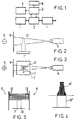
- Fig. 1 presents, by way of a principle block diagram, the design and operation of a bottle receiving means.
- Fig. 2 presents in elevational view the principle construction of the identifying means belonging to the receiver means of Fig. 1, in elevational view.
- Fig. 3 presents the same means as Fig. 2, viewed from above.
- Fig. 4 illustrates the forming of a line image of the bottle under examination, with an identifying means as shown in Figs 2-3.
- Fig. 5 presents the identifying means of another embodiment of the bottle receiving means, in elevational view.
- Fig. 6 presents a mirror system interposed between the illuminating means and the detector, in a bottle receiving means.
- Fig. 7 presents another mirror system interposed between the illuminating means and the detector, in a bottle receiving means.
- Fig. 8 presents a third mirror system interposed between the illuminating means and the detector, in a bottle receiving means.
- Fig. 9 presents a fourth mirror system interposed between the illuminating means and the detector, in a bottle receiving means.
- The application of a bottle receiving means conforming to an embodiment of the invention, presented by way of example in Fig. 1, comprises a transport means or a transport apparatus 1 for transporting bottles, an identifying means 2 with
data processing unit 3 for identifying and accepting bottles having given shapes, and a recording means 4 for recording the accepted bottles. The transport means 1 may consist e.g. of one or several belt conveyors, of a rotary disk conveyor, or in general of any kind of conveyor suitable for transporting bottles. The conveyor may be disposed to transport bottles in horizontal direction and/or possibly in vertical direction; however, horizontal transport is considered most appropriate in connection with a bottle receiving means according to the invention. The transport apparatus may further comprise a feeder means for feeding bottles to the transport means, and a removal means for removing the bottles at the end of the transport means, e.g. onto the floor of a storage space, into a bottle hamper, etc. - The identifying means 2 comprises, advantageously, a
data processing unit 3 with memory unit 8 and recording unit 4, if any. Thedata processing unit 3 is thus provided with a file specifying acceptable bottle shapes, that is, the data of acceptable bottle shapes may be entered in the file for comparison of the information obtained from bottles with the equivalent information on acceptable bottle shapes. The recording means records the number of accepted bottles, possibly their sizes and/or the amount of money to be debited or refunded. - Figs 2-3 show, in a schematic principle diagram, an identifying means 2, comprising a mainly stationary
illuminating means 5 for illuminating thebottle 10, adetector 6 for examining the bottle, and aconveyor 7 for moving the bottle past the detector. Said detector has been disposed to examine the bottle at discrete moments, at time intervals, at lineal locations, as the bottle moves, transported by theconveyor 7, past the detector in such manner that the lineal examined locations yield information at least on the shape of the bottle's neck and upper part, that is, the detector has been disposed to register a so-called line image of the bottle. - When registering said line image, the detector is thus understood to register, at intervals, line images of the bottle, as shown in Fig. 4, while the bottle is moved past the detector by the
conveyor 7. Such line images may be taken at desired time intervals, that is, the line spacing of the image can be regulated to be as desired, according to the desired accuracy of information. Thedetector 6 converts the line image received into electric pulses, to be conducted to a data processing unit as shown in Fig. 1, in a manner known in the art. - It is not absolutely necessary to register a line image of the whole bottle; it is usually sufficient to project the image of the upper part 10' of the bottle, as shown in Fig. 4, since the specific characteristics of different bottle types and models are usually best apparent in the upper part of the bottle. The lower part 10'' of the bottle is then appropriately excluded from the image process.
- In Figs 2-3 a conventional lineal camera has been used for
detector 6, this camera being arranged to produce an image of the bottle moving past in front of the camera in lateral direction at right angles against the alignment of the camera objective, in the region of the upper part of the bottle's neck, in the form of vertical line images at 1 mm spacing. The identifying means has been programmed to measure the height of the bottle. If desired, thedetector 6 may be arranged to produce horizontal images of the bottle, in which case theconveyor 7 is appropriately disposed to transport the bottle in vertical direction for viewing the bottle at desired height. - By using a lineal camera for
detector 6, certain advantages are gained, compared for instance with an identifying means based on laser. In the first place, a lineal camera is substantially less expensive than a laser. The lineal camera usually requires far less maintenance than any laser apparatus. The lineal camera is reliable in operation and construction, tolerating vibration and other external stresses. The lineal camera may for instance consist of a so-called CCD (Charge Coupled Diode) camera or, for instance, of a so-called photodiode camera (Self Scanning Array). A lineal camera may further with ease be connected to a data processing unit, and the information delivered by the lineal camera, i.e., an electric signal sequence, is eminently suited to be used substantially as it is in a data processing unit. Furthermore, the lineal camera can be adjusted and timed with ease regarding the scanning rate, that is, the image-recording interval. - In Fig. 5 is seen another embodiment, in which the bottle under examination has been conducted to pass, on a conveyor, through a gate constituted by a row of
diodes 12 emitting IR light and a vertical row formed by light-receivingphotodiodes 13. The IR-light-emitting diodes and the corresponding light-measuring photodiodes then constitute an identifying means in which the diodes have been arranged to measure the height of the bottle at time intervals, that is, to record vertical line images of the bottle. The timing of the photodiodes is used to regulate the line spacing of the line image, i.e., the resolution of the image. - In the embodiments here presented, the bottle under examination has been disposed to be transported in upright position. If desired, the transport apparatus 1 and/or the
conveyor 7 may be arranged to move the bottle relative to the detector in horizontal position as well, that is, with the mouth of the bottle pointing in horizontal direction. Furthermore, in the embodiments that have been presented thedetector 6, i.e., the lineal camera, respectively the row ofphotodiodes 13, has been disposed to be stationary. Alternatively, the lineal cameras, or said photodiodes, may equally be disposed to scan the bottle for recording an image of the bottle, although this last-mentioned design is more complex and consequently more expensive. - In the embodiment of Fig. 6 a mirror system has been interposed between the illuminating means 5 and the
detector 6, said mirror system consisting of onemirror 14 in this embodiment. - In the embodiment of Fig. 7 a mirror system has been interposed between the illuminating means 5 and the
detector 6, said mirror system consisting of afirst mirror 24 and asecond mirror 25 in this embodiment. - In the embodiment of Fig. 8 a mirror system has been interposed between the illuminating means 5 and the
detector 6, this mirror system consisting in this embodiment of afirst mirror 34, asecond mirror 35 and athird mirror 36. Thefirst mirror 34 is an auxiliary mirror, and the second andthird mirrors mirrors - In the embodiment of Fig. 9 a mirror system has been interposed between the illuminating means 5 and the
detector 6, this mirror system consisting of fourmirrors mirrors 44 and 47 are auxiliary mirrors, and themirrors
Claims (5)
- A bottle receiving means comprising a transport apparatus (1) for transporting bottles, an identifying means (2) with data processing unit (3) for identifying and accepting bottles having certain given shapes, and a recording means (4) for recording accepted bottles, said identifying means (2) comprising a stationary lineal illuminating means (5) for illuminating said bottle, a detector (6) for examining said bottle, and a conveyor (7) for moving said bottle between said illuminating means (5) and said detector so that the detector examines a line image of the shape of at least the bottle's neck and upper part (10') from behind the bottle as referred to the illuminating means,
characterized in that between said conveyor (7) and said detector (6) there is interposed a stationary mirror system (14;24;25;34;35;36;44,45,46,47) without increasing the structural dimensions of said identifying means (2), whereby even major positional errors of the bottles on said conveyor (7) cause no worthwhile error in height, which approaches zero with increasing focal length, by the aid of which mirror system the optical path in a horizontal direction between the bottle and said detector (6) is folded for increasing the optical length of said mirror system. - A bottle receiving means according to claim 1,
characterized in that said mirror system consists of one mirror (14). - A bottle receiving means according to claim 1,
characterized in that said mirror system consists of two mirrors (24, 25). - A bottle receiving means according to claim 1,
characterized in that said mirror system consists of three mirrors (34, 35, 36), the first mirror (34) being an auxiliary mirror and the second and third (35, 36) being principal mirrors. - A bottle receiving means according to claim 1,
characterized in that said mirror system consists of four mirrors (44, 45, 46, 47), the first mirror (44) and the fourth mirror (47) being auxiliary mirrors and the second mirror and the third mirror (45, 46) being principal mirrors.
Applications Claiming Priority (2)
| Application Number | Priority Date | Filing Date | Title |
|---|---|---|---|
| FI870904A FI77390B (en) | 1987-03-02 | 1987-03-02 | MOTTAGNINGSANORDNING FOER FLASKOR. |
| FI870904 | 1987-03-02 |
Publications (4)
| Publication Number | Publication Date |
|---|---|
| EP0280933A2 EP0280933A2 (en) | 1988-09-07 |
| EP0280933A3 EP0280933A3 (en) | 1989-08-30 |
| EP0280933B1 EP0280933B1 (en) | 1994-06-01 |
| EP0280933B2 true EP0280933B2 (en) | 1997-08-06 |
Family
ID=8524051
Family Applications (1)
| Application Number | Title | Priority Date | Filing Date |
|---|---|---|---|
| EP88101892A Expired - Lifetime EP0280933B2 (en) | 1987-03-02 | 1988-02-09 | Bottle receiving means |
Country Status (9)
| Country | Link |
|---|---|
| US (1) | US4885461A (en) |
| EP (1) | EP0280933B2 (en) |
| AT (1) | ATE106283T1 (en) |
| CA (1) | CA1294708C (en) |
| DE (1) | DE3889743T3 (en) |
| ES (1) | ES2053594T5 (en) |
| FI (1) | FI77390B (en) |
| GR (1) | GR3024444T3 (en) |
| NO (1) | NO302449B1 (en) |
Families Citing this family (13)
| Publication number | Priority date | Publication date | Assignee | Title |
|---|---|---|---|---|
| DE4023149A1 (en) * | 1990-07-20 | 1992-01-23 | Kodak Ag | DEVICE FOR SCANING CONTAINERS WITH A LIQUID |
| FR2681133A1 (en) * | 1991-09-11 | 1993-03-12 | Languedoc Verrerie | LIGHT EMITTING OR ABSORBING DEVICE FOR THE CONTACTLESS CONTROL OF OBJECTS. |
| US5349199A (en) * | 1993-04-29 | 1994-09-20 | Xerox Corporation | Sensing apparatus for reducing sheet detection and registration errors by using multiple light beam reflections |
| US5661561A (en) * | 1995-06-02 | 1997-08-26 | Accu-Sort Systems, Inc. | Dimensioning system |
| JP3032159B2 (en) * | 1996-09-24 | 2000-04-10 | 株式会社日立製作所 | Analysis system |
| DE19911351A1 (en) * | 1999-03-15 | 2000-09-21 | Olympus Diagnostica Gmbh | Profile scanner |
| US7120284B2 (en) * | 2003-07-18 | 2006-10-10 | Emhart Glass S.A. | Container inspection machine |
| DE102004049260A1 (en) * | 2004-10-09 | 2006-04-13 | Krones Ag | Device and method for detecting containers and / or containers |
| US7490773B2 (en) * | 2004-12-03 | 2009-02-17 | Mcvicker Henry J | Apparatus and method for obtaining an image of an arcuate surface |
| DE102005035410A1 (en) * | 2005-07-28 | 2007-02-01 | Robert Bosch Gmbh | Optical detecting device for packaged foods, has camera for visual detection of packaged goods that are fed on conveyor, and mirrors deflecting beam paths of camera to form beam paths, which are larger than vertical dimension of housing |
| DK2164028T3 (en) * | 2008-09-15 | 2014-02-24 | Frewitt Printing Sa | Reading device and reading process for the code markings on the containers |
| DE102008054109A1 (en) * | 2008-10-31 | 2010-05-12 | Khs Ag | Method and device for identifying objects |
| US8823770B2 (en) | 2012-01-26 | 2014-09-02 | Meditory Llc | Device and methods for fabricating a two-dimensional image of a three-dimensional object |
Family Cites Families (9)
| Publication number | Priority date | Publication date | Assignee | Title |
|---|---|---|---|---|
| US3563379A (en) * | 1968-11-12 | 1971-02-16 | Barry Wehmiller Co | Container fill level inspection apparatus |
| US3955179A (en) * | 1971-12-14 | 1976-05-04 | Tore Planke | Apparatus for automatic pattern recognition and registration of empty bottles |
| US3942127A (en) * | 1975-04-11 | 1976-03-02 | The United States Of America As Represented By The Secretary Of The Navy | Aspheric cassegrain laser power amplifier system |
| JPS524950A (en) * | 1975-07-02 | 1977-01-14 | Hitachi Ltd | Welding method of the runner of the hydraulic machine |
| SE405214B (en) * | 1977-08-24 | 1978-11-27 | Hugin Kassaregister Ab | APPARATUS FOR IDENTIFICATION AND REGISTRATION OF BOTTLES |
| US4367405A (en) * | 1977-10-13 | 1983-01-04 | Ti Fords Limited | Bottle inspection apparatus |
| US4476533A (en) * | 1981-07-08 | 1984-10-09 | Ball Corporation | Glassware gauging system |
| FI71892B (en) | 1982-09-24 | 1986-11-28 | Halton Oy | MOTTAGNINGSANORDNING FOER FLASKOR |
| FR2558259B1 (en) * | 1984-01-17 | 1986-12-12 | Saint Gobain Cinematique Contr | SCANNING TRANSMITTER FOR OPTICAL INSPECTION OF TRANSPARENT ITEMS |
-
1987
- 1987-03-02 FI FI870904A patent/FI77390B/en not_active Application Discontinuation
-
1988
- 1988-02-09 ES ES88101892T patent/ES2053594T5/en not_active Expired - Lifetime
- 1988-02-09 AT AT88101892T patent/ATE106283T1/en not_active IP Right Cessation
- 1988-02-09 EP EP88101892A patent/EP0280933B2/en not_active Expired - Lifetime
- 1988-02-09 DE DE3889743T patent/DE3889743T3/en not_active Expired - Fee Related
- 1988-03-01 NO NO880897A patent/NO302449B1/en not_active IP Right Cessation
- 1988-03-02 CA CA000560318A patent/CA1294708C/en not_active Expired - Lifetime
- 1988-03-02 US US07/162,872 patent/US4885461A/en not_active Expired - Lifetime
-
1997
- 1997-08-13 GR GR970402087T patent/GR3024444T3/en unknown
Also Published As
| Publication number | Publication date |
|---|---|
| ATE106283T1 (en) | 1994-06-15 |
| DE3889743T3 (en) | 1998-09-17 |
| NO302449B1 (en) | 1998-03-02 |
| EP0280933B1 (en) | 1994-06-01 |
| NO880897L (en) | 1988-09-05 |
| CA1294708C (en) | 1992-01-21 |
| FI77390B (en) | 1988-11-30 |
| ES2053594T3 (en) | 1994-08-01 |
| EP0280933A2 (en) | 1988-09-07 |
| GR3024444T3 (en) | 1997-11-28 |
| NO880897D0 (en) | 1988-03-01 |
| FI870904A (en) | 1988-09-03 |
| DE3889743T2 (en) | 1994-10-20 |
| ES2053594T5 (en) | 1997-10-16 |
| EP0280933A3 (en) | 1989-08-30 |
| FI870904A0 (en) | 1987-03-02 |
| DE3889743D1 (en) | 1994-07-07 |
| US4885461A (en) | 1989-12-05 |
Similar Documents
| Publication | Publication Date | Title |
|---|---|---|
| EP0280933B2 (en) | Bottle receiving means | |
| EP1106993B1 (en) | Glass-container neck-finish check detection | |
| KR0185693B1 (en) | A high precision component alignment sensor system | |
| US4798963A (en) | Apparatus for monitoring and measuring the quality of rail wheel still mounted beneath a rail vehicle without directly contacting the rail wheels | |
| GB2288016A (en) | A device for generating, detecting and recognizing a contour image of a liquid container | |
| CA2330793C (en) | Container sealing surface area inspection | |
| EP1635166A2 (en) | Container sealing surface area inspection | |
| EP0174549B1 (en) | Means for identifying and recording bottles and/or bottle hampers | |
| EP0336476A1 (en) | Inspection device | |
| CN1052947A (en) | Apparatus for three-dimensional inspection of hollow | |
| JP3011397B2 (en) | Inspection method and device for transparent container | |
| EP0293510B1 (en) | Apparatus for inspecting side-wall of bottle | |
| EP0644417A1 (en) | Inspection of translucent containers | |
| EP1288613A2 (en) | Sidewall thickness measurement with a line shaped light beam or for several transparent containers | |
| JPH08210990A (en) | Method and equipment for inspecting object | |
| EP0894262B1 (en) | Optical inspection device and lithographic apparatus provided with such a device | |
| US20070030476A1 (en) | Detection system for use in a sorting apparatus, a method for determining drift in the detection system and a sorting apparatus comprising such detection system | |
| EP0429086B1 (en) | Inspection device on the basis of dark field illumination | |
| US4851913A (en) | Picture recording apparatus | |
| GB2261505A (en) | Optical monitoring of container filling | |
| JPH06214086A (en) | Inspection device of edge of cylindrical object | |
| FI71892B (en) | MOTTAGNINGSANORDNING FOER FLASKOR | |
| US6897463B1 (en) | Wafer carrier mapping sensor assembly | |
| JPS63241510A (en) | Optical type scanner with telecentric train camera | |
| AU606679B2 (en) | Optical inspection system for cylindrical objects |
Legal Events
| Date | Code | Title | Description |
|---|---|---|---|
| PUAI | Public reference made under article 153(3) epc to a published international application that has entered the european phase |
Free format text: ORIGINAL CODE: 0009012 |
|
| AK | Designated contracting states |
Kind code of ref document: A2 Designated state(s): AT BE CH DE ES FR GB GR IT LI LU NL SE |
|
| PUAL | Search report despatched |
Free format text: ORIGINAL CODE: 0009013 |
|
| AK | Designated contracting states |
Kind code of ref document: A3 Designated state(s): AT BE CH DE ES FR GB GR IT LI LU NL SE |
|
| 17P | Request for examination filed |
Effective date: 19891102 |
|
| 17Q | First examination report despatched |
Effective date: 19920213 |
|
| GRAA | (expected) grant |
Free format text: ORIGINAL CODE: 0009210 |
|
| AK | Designated contracting states |
Kind code of ref document: B1 Designated state(s): AT BE CH DE ES FR GB GR IT LI LU NL SE |
|
| REF | Corresponds to: |
Ref document number: 106283 Country of ref document: AT Date of ref document: 19940615 Kind code of ref document: T |
|
| REF | Corresponds to: |
Ref document number: 3889743 Country of ref document: DE Date of ref document: 19940707 |
|
| ITF | It: translation for a ep patent filed |
Owner name: ST. CONSUL.BREVETTUALE S.R.L. |
|
| REG | Reference to a national code |
Ref country code: ES Ref legal event code: FG2A Ref document number: 2053594 Country of ref document: ES Kind code of ref document: T3 |
|
| ET | Fr: translation filed | ||
| REG | Reference to a national code |
Ref country code: GR Ref legal event code: FG4A Free format text: 3012617 |
|
| EAL | Se: european patent in force in sweden |
Ref document number: 88101892.3 |
|
| PLBI | Opposition filed |
Free format text: ORIGINAL CODE: 0009260 |
|
| 26 | Opposition filed |
Opponent name: TOMRA SYTEMS A/S Effective date: 19950228 |
|
| NLR1 | Nl: opposition has been filed with the epo |
Opponent name: TOMRA SYTEMS A/S |
|
| PGFP | Annual fee paid to national office [announced via postgrant information from national office to epo] |
Ref country code: LU Payment date: 19960101 Year of fee payment: 9 |
|
| PLAW | Interlocutory decision in opposition |
Free format text: ORIGINAL CODE: EPIDOS IDOP |
|
| PG25 | Lapsed in a contracting state [announced via postgrant information from national office to epo] |
Ref country code: LU Free format text: LAPSE BECAUSE OF NON-PAYMENT OF DUE FEES Effective date: 19970209 |
|
| PLAW | Interlocutory decision in opposition |
Free format text: ORIGINAL CODE: EPIDOS IDOP |
|
| PUAH | Patent maintained in amended form |
Free format text: ORIGINAL CODE: 0009272 |
|
| STAA | Information on the status of an ep patent application or granted ep patent |
Free format text: STATUS: PATENT MAINTAINED AS AMENDED |
|
| 27A | Patent maintained in amended form |
Effective date: 19970806 |
|
| AK | Designated contracting states |
Kind code of ref document: B2 Designated state(s): AT BE CH DE ES FR GB GR IT LI LU NL SE |
|
| PG25 | Lapsed in a contracting state [announced via postgrant information from national office to epo] |
Ref country code: GR Free format text: THE PATENT HAS BEEN ANNULLED BY A DECISION OF A NATIONAL AUTHORITY Effective date: 19970813 |
|
| REG | Reference to a national code |
Ref country code: CH Ref legal event code: AEN Free format text: AUFRECHTERHALTUNG DES PATENTES IN GEAENDERTER FORM |
|
| NLR2 | Nl: decision of opposition | ||
| NLR3 | Nl: receipt of modified translations in the netherlands language after an opposition procedure | ||
| REG | Reference to a national code |
Ref country code: ES Ref legal event code: DC2A Kind code of ref document: T5 Effective date: 19970919 |
|
| ITF | It: translation for a ep patent filed |
Owner name: STUDIO CONS. BREVETTUALE S.R.L. |
|
| REG | Reference to a national code |
Ref country code: GR Ref legal event code: FG4A Free format text: 3024444 |
|
| ET3 | Fr: translation filed ** decision concerning opposition | ||
| REG | Reference to a national code |
Ref country code: GB Ref legal event code: 732E |
|
| REG | Reference to a national code |
Ref country code: FR Ref legal event code: TP |
|
| NLS | Nl: assignments of ep-patents |
Owner name: HALTON SYSTEM OY |
|
| REG | Reference to a national code |
Ref country code: ES Ref legal event code: PC2A |
|
| REG | Reference to a national code |
Ref country code: CH Ref legal event code: PUE Owner name: HALTON OY TRANSFER- TOMRA SYSTEMS OY |
|
| PGFP | Annual fee paid to national office [announced via postgrant information from national office to epo] |
Ref country code: ES Payment date: 20010209 Year of fee payment: 14 |
|
| REG | Reference to a national code |
Ref country code: GB Ref legal event code: IF02 |
|
| PGFP | Annual fee paid to national office [announced via postgrant information from national office to epo] |
Ref country code: BE Payment date: 20020131 Year of fee payment: 15 |
|
| PGFP | Annual fee paid to national office [announced via postgrant information from national office to epo] |
Ref country code: AT Payment date: 20020208 Year of fee payment: 15 |
|
| PGFP | Annual fee paid to national office [announced via postgrant information from national office to epo] |
Ref country code: GR Payment date: 20020213 Year of fee payment: 15 Ref country code: GB Payment date: 20020213 Year of fee payment: 15 |
|
| PGFP | Annual fee paid to national office [announced via postgrant information from national office to epo] |
Ref country code: SE Payment date: 20020215 Year of fee payment: 15 |
|
| PGFP | Annual fee paid to national office [announced via postgrant information from national office to epo] |
Ref country code: NL Payment date: 20020228 Year of fee payment: 15 |
|
| PGFP | Annual fee paid to national office [announced via postgrant information from national office to epo] |
Ref country code: DE Payment date: 20020327 Year of fee payment: 15 |
|
| PGFP | Annual fee paid to national office [announced via postgrant information from national office to epo] |
Ref country code: CH Payment date: 20020530 Year of fee payment: 15 |
|
| PGFP | Annual fee paid to national office [announced via postgrant information from national office to epo] |
Ref country code: FR Payment date: 20030128 Year of fee payment: 16 |
|
| PG25 | Lapsed in a contracting state [announced via postgrant information from national office to epo] |
Ref country code: GB Free format text: LAPSE BECAUSE OF NON-PAYMENT OF DUE FEES Effective date: 20030209 Ref country code: AT Free format text: LAPSE BECAUSE OF NON-PAYMENT OF DUE FEES Effective date: 20030209 |
|
| PG25 | Lapsed in a contracting state [announced via postgrant information from national office to epo] |
Ref country code: SE Free format text: LAPSE BECAUSE OF NON-PAYMENT OF DUE FEES Effective date: 20030210 Ref country code: ES Free format text: LAPSE BECAUSE OF NON-PAYMENT OF DUE FEES Effective date: 20030210 |
|
| PG25 | Lapsed in a contracting state [announced via postgrant information from national office to epo] |
Ref country code: LI Free format text: LAPSE BECAUSE OF NON-PAYMENT OF DUE FEES Effective date: 20030228 Ref country code: CH Free format text: LAPSE BECAUSE OF NON-PAYMENT OF DUE FEES Effective date: 20030228 Ref country code: BE Free format text: LAPSE BECAUSE OF NON-PAYMENT OF DUE FEES Effective date: 20030228 |
|
| PG25 | Lapsed in a contracting state [announced via postgrant information from national office to epo] |
Ref country code: NL Free format text: LAPSE BECAUSE OF NON-PAYMENT OF DUE FEES Effective date: 20030901 |
|
| PG25 | Lapsed in a contracting state [announced via postgrant information from national office to epo] |
Ref country code: DE Free format text: LAPSE BECAUSE OF NON-PAYMENT OF DUE FEES Effective date: 20030902 |
|
| EUG | Se: european patent has lapsed | ||
| GBPC | Gb: european patent ceased through non-payment of renewal fee | ||
| REG | Reference to a national code |
Ref country code: CH Ref legal event code: PL |
|
| NLV4 | Nl: lapsed or anulled due to non-payment of the annual fee |
Effective date: 20030901 |
|
| REG | Reference to a national code |
Ref country code: ES Ref legal event code: FD2A Effective date: 20030210 |
|
| PG25 | Lapsed in a contracting state [announced via postgrant information from national office to epo] |
Ref country code: FR Free format text: LAPSE BECAUSE OF NON-PAYMENT OF DUE FEES Effective date: 20041029 |
|
| REG | Reference to a national code |
Ref country code: FR Ref legal event code: ST |
|
| PG25 | Lapsed in a contracting state [announced via postgrant information from national office to epo] |
Ref country code: IT Free format text: LAPSE BECAUSE OF NON-PAYMENT OF DUE FEES;WARNING: LAPSES OF ITALIAN PATENTS WITH EFFECTIVE DATE BEFORE 2007 MAY HAVE OCCURRED AT ANY TIME BEFORE 2007. THE CORRECT EFFECTIVE DATE MAY BE DIFFERENT FROM THE ONE RECORDED. Effective date: 20050209 |