EP0280778A2 - Kühlung für eine Dichtungsvorrichtung - Google Patents
Kühlung für eine Dichtungsvorrichtung Download PDFInfo
- Publication number
- EP0280778A2 EP0280778A2 EP87118079A EP87118079A EP0280778A2 EP 0280778 A2 EP0280778 A2 EP 0280778A2 EP 87118079 A EP87118079 A EP 87118079A EP 87118079 A EP87118079 A EP 87118079A EP 0280778 A2 EP0280778 A2 EP 0280778A2
- Authority
- EP
- European Patent Office
- Prior art keywords
- sealing
- cooling
- ring
- shaft
- fluid
- Prior art date
- Legal status (The legal status is an assumption and is not a legal conclusion. Google has not performed a legal analysis and makes no representation as to the accuracy of the status listed.)
- Ceased
Links
Images
Classifications
-
- F—MECHANICAL ENGINEERING; LIGHTING; HEATING; WEAPONS; BLASTING
- F16—ENGINEERING ELEMENTS AND UNITS; GENERAL MEASURES FOR PRODUCING AND MAINTAINING EFFECTIVE FUNCTIONING OF MACHINES OR INSTALLATIONS; THERMAL INSULATION IN GENERAL
- F16J—PISTONS; CYLINDERS; SEALINGS
- F16J15/00—Sealings
- F16J15/16—Sealings between relatively-moving surfaces
- F16J15/162—Special parts or details relating to lubrication or cooling of the sealing itself
Definitions
- the present invention relates to a new type of sealing arrangement for rotating shafts. It is particularly suitable for shaft sealing of centrifugal pumps used for pumping of hot fluids.
- US patent 4,498,681 discloses an example of direct cooling.
- a spacing ring is disposed between the sealing elements which are cord packings, to which ring cold fluid is fed from outside, said fluid mixing with hot leaking fluid and cooling it, this preventing it from boiling in the area of the seals to follow.
- the spacing ring is mostly a metal or plastic ring, its cross section being H-shaped, and it has borings or equivalent openings arranged through its axial center ring, through which openings the cooling/lubricating fluid enters the shaft or the shaft sleeve.
- Such an arrangement has, however, some disadvantages, because the amount of fluid leaking from the pump shaft is greater and the shaft or the shaft sleeve may cool too much.
- An alternative is cooling of the entire sealing cage, which most commonly is arranged by providing the sealing cage with a hollow space in either the flowing direction of the fluid before the sealings or in the area of sealings.
- the purpose of the arrangement is to keep the sealing cage cool enough to cool the fluid entered between the shaft and said sealing cage sufficiently to prevent it from boiling when the pressure has decreased in the sealing area. Cooling in the sealing area has to be highly efficient to really have an effect, through the sealings, on the fluid between the sealings and the shaft or between the shaft sleeves.
- the construction of this arrangement is exacting, and the manufacture of the hollow space in the sealing cage adds to the costs, thus increasing the manufacturing costs of the pump. It is also possible that the shaft will cool as well, which is not necessarily desirable because of the heat stresses and heat expansion.
- a sealing arrangement which has a simple and economical construction and which is applicable to all sealings.
- a preferred embodiment of the invention is characterized in that, along with at least one sealing element is arranged a cooling ring, the outer periphery of which is sealed to the sealing cage.
- Another preferred embodiment of the invention is characterized in that, between at least two sealing elements there is arranged a cooling ring, the outer periphery of which is provided with a ring space being tight relative to the shaft/shaft sleeve and the sealing cage.
- the invention has the particular advantages that a separate cooling fluid is used and not the pumping fluid so that any appropriate fluid may be used, which does not necessarily have to possess lubricating properties and the number of necessary seals is reduced producing a sealing cage of simple construction. Further relevant features of the invention are described in the subclaims.
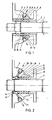
- the drive end of the pump comprises a shaft 1, a shaft sleeve 2 rotating along with the shaft, a sealing cage 3, sealing rings 4 to 7, a tightening sleeve 8, a cooling ring 9 and inlet and outlet connections 10 and 11, said connections being preferably disposed vertically on the opposite sides of the shaft.
- the cross section of the cooling ring 9 is preferably U-shaped and said ring is sealed with O-rings 12 and 13 to the sealing cage 3. There is a small clearance 14 between the cooling ring 9 and the shaft 1, into which clearance the fluid leaked through the sealings 4 and 5 is collected.
- the cooling ring 9 is disposed between the sealing rings 5 and 6 because it has been established in trials that the pressure of the leaking fluid drops so much while said fluid is passing by two sealing rings that there is a risk of the fluid beginning to vaporize. In that case it is preferable to cool the leaking fluid to such an extent that it will no longer vaporize.
- the embodiment in accordance with Fig. 2 deviates from the embodiment of Fig. 1 in, for example, that the cooling ring 19 is disposed before the sealings 4 to 7, in which case the cooling fluid connections 20 and 21 have correspondingly been transferred towards the impeller.
- Such an arrangement is applicable, for example, when the pumping fluid is hot and the pressure is not very high. The risk of vaporization of the fluid would, however, be involved. Therefore, it is safer to cool the leaking fluid already before the sealing area.
- Another difference is that there is no shaft sleeve on top of the shaft 1.
- the arrangement of the invention functions in such a way that cooling fluid is fed to the ring space 15 of the cooling ring 9, 19 from the connections 10, 20.
- the cooling fluid When the cooling fluid has circulated half a turn in the ring space 15, it is removed through the connections 11, 21. Access of the cooling fluid to the sealings 4 to 7 is prevented by O-rings 12 and 13.
- any appropriate fluid may be used as a cooling fluid because it will come into contact with neither the pumping fluid nor the sealings 4 to 7.
- the cooling fluid need not therefore have a lubricating property.
- the cooling fluid While flowing in the ring space 15, the cooling fluid cools the ring 9, 19, which in turn receives heat mainly from the leaking fluid in the clearance 14 and to some extent from adjacent sealings 5, 6 and 4.
- the cooling effect of the ring 9 extends to the area of the sealing ring 5, whereby the cooling of the fluid begins already there.
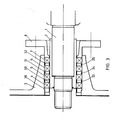
- Fig. 3 illustrates a third embodiment of the invention, which comprises several cooling rings 30 to 32 that are disposed between the sealings 4 through 7.
- the cooling rings 30 to 32 are characterized in that they are solid, not provided with a hollow space, and conduct heat well and that their outer periphery is provided with a groove, in which is disposed the O-ring 33 to 35, which seals the cooling ring 30 to 32 to the sealing cage 3. It is also possible that the circumference of already the first ring 36 is sealed with an O-ring.
- the arrangement of Fig. 3 functions in such a way that while a pressurized fluid is apt to penetrate the slots of both the outer and the inner peripheries of the sealings 4 to 7 as well as the radial slots, the slots are of the outer periphery and the radial slots are quickly filled so as to prevent the fluid from leaking past the sealings thanks to the O-rings.
- the only remaining leakage route is the slot between the sealings 4 to 7 and the sleeve 2. Thereby, the pressure of the leaking fluid is prevented from decreasing quickly and no vaporization of the fluid occurs.
- the cooling rings 30 to 32 form a beautiful heat bridge between the third leakage route and the sealing cage, especially when the outer periphery of the cooling rings 30 to 32 is, through the fluid, connected to the sealing cage so that it conducts heat well.
- the pressurized fluid cools efficiently and the amount of the leaking fluid is at the same time reduced.
- the number of necessary sealings is also cut down because there is only one leakage route i.e. the slot between the sealing and the shaft sleeve.
- the most important advantage achieved by the arrangement is a sealing cage of a simple construction (with no cooling connections).
- the invention introduces an entirely new sealing arrangment, which eliminates the disadvantage of the equipment of the prior art and which is economical and calls for no special arrangements in the sealing cage or in other parts of the drive end of the pump.
- the sealing arrangement can be made adjustable by, for example, providing the shaft sleeve or the shaft with a temperature measuring system, which enables the optimization of the amount of cooling liquid.
- the pump is adjustable to suit various operating conditions by arranging a cooling ring already at the manufacturing stage, to a desired shaft position relative to the sealings.
Landscapes
- Engineering & Computer Science (AREA)
- General Engineering & Computer Science (AREA)
- Mechanical Engineering (AREA)
- Structures Of Non-Positive Displacement Pumps (AREA)
- Sealing Devices (AREA)
- Types And Forms Of Lifts (AREA)
- Rolling Contact Bearings (AREA)
Applications Claiming Priority (2)
| Application Number | Priority Date | Filing Date | Title |
|---|---|---|---|
| FI864981 | 1986-12-08 | ||
| FI864981A FI76193C (fi) | 1986-12-08 | 1986-12-08 | Taetningssystem. |
Publications (2)
| Publication Number | Publication Date |
|---|---|
| EP0280778A2 true EP0280778A2 (de) | 1988-09-07 |
| EP0280778A3 EP0280778A3 (de) | 1989-02-15 |
Family
ID=8523615
Family Applications (1)
| Application Number | Title | Priority Date | Filing Date |
|---|---|---|---|
| EP87118079A Ceased EP0280778A3 (de) | 1986-12-08 | 1987-12-07 | Kühlung für eine Dichtungsvorrichtung |
Country Status (3)
| Country | Link |
|---|---|
| EP (1) | EP0280778A3 (de) |
| JP (1) | JPS63214575A (de) |
| FI (1) | FI76193C (de) |
Cited By (6)
| Publication number | Priority date | Publication date | Assignee | Title |
|---|---|---|---|---|
| WO2010144022A1 (en) * | 2009-06-12 | 2010-12-16 | Alfa Laval Corporate Ab | Cooling device for spindle sealing and/or bearing means |
| CN102425670A (zh) * | 2011-12-02 | 2012-04-25 | 湘潭大学 | 轴端串联o型橡胶密封圈密封结构 |
| US8814508B2 (en) | 2003-09-18 | 2014-08-26 | General Electric Company | Heat exchanger for centrifugal compressor gas sealing |
| CN110005810A (zh) * | 2019-03-20 | 2019-07-12 | 西安交通大学 | 一种高温炉窑动态密封结构 |
| CN110762192A (zh) * | 2018-07-25 | 2020-02-07 | 江苏泰隆减速机股份有限公司 | 一种双油封布置透盖 |
| CN112145656A (zh) * | 2020-09-25 | 2020-12-29 | 中国兵器装备集团自动化研究所 | 一种含能材料密封轴套装置 |
Citations (3)
| Publication number | Priority date | Publication date | Assignee | Title |
|---|---|---|---|---|
| US2143637A (en) * | 1937-05-12 | 1939-01-10 | Carl W Vollmann | Refrigerating system |
| FR2097710A5 (de) * | 1970-07-11 | 1972-03-03 | Halbergerhuette Gmbh | |
| DE3347263A1 (de) * | 1983-12-28 | 1985-07-11 | Rheinhütte vorm. Ludwig Beck GmbH & Co, 6200 Wiesbaden | Verfahren und vorrichtung zur abdichtung von pumpenwellen |
-
1986
- 1986-12-08 FI FI864981A patent/FI76193C/fi not_active IP Right Cessation
-
1987
- 1987-12-07 EP EP87118079A patent/EP0280778A3/de not_active Ceased
- 1987-12-08 JP JP62310778A patent/JPS63214575A/ja active Pending
Patent Citations (3)
| Publication number | Priority date | Publication date | Assignee | Title |
|---|---|---|---|---|
| US2143637A (en) * | 1937-05-12 | 1939-01-10 | Carl W Vollmann | Refrigerating system |
| FR2097710A5 (de) * | 1970-07-11 | 1972-03-03 | Halbergerhuette Gmbh | |
| DE3347263A1 (de) * | 1983-12-28 | 1985-07-11 | Rheinhütte vorm. Ludwig Beck GmbH & Co, 6200 Wiesbaden | Verfahren und vorrichtung zur abdichtung von pumpenwellen |
Cited By (8)
| Publication number | Priority date | Publication date | Assignee | Title |
|---|---|---|---|---|
| US8814508B2 (en) | 2003-09-18 | 2014-08-26 | General Electric Company | Heat exchanger for centrifugal compressor gas sealing |
| WO2010144022A1 (en) * | 2009-06-12 | 2010-12-16 | Alfa Laval Corporate Ab | Cooling device for spindle sealing and/or bearing means |
| US9416877B2 (en) | 2009-06-12 | 2016-08-16 | Alfa Laval Corporate Ab | Cooling device for spindle sealing and/or bearing means |
| CN102425670A (zh) * | 2011-12-02 | 2012-04-25 | 湘潭大学 | 轴端串联o型橡胶密封圈密封结构 |
| CN102425670B (zh) * | 2011-12-02 | 2014-10-15 | 湘潭大学 | 轴端串联o型橡胶密封圈密封结构 |
| CN110762192A (zh) * | 2018-07-25 | 2020-02-07 | 江苏泰隆减速机股份有限公司 | 一种双油封布置透盖 |
| CN110005810A (zh) * | 2019-03-20 | 2019-07-12 | 西安交通大学 | 一种高温炉窑动态密封结构 |
| CN112145656A (zh) * | 2020-09-25 | 2020-12-29 | 中国兵器装备集团自动化研究所 | 一种含能材料密封轴套装置 |
Also Published As
| Publication number | Publication date |
|---|---|
| JPS63214575A (ja) | 1988-09-07 |
| FI76193B (fi) | 1988-05-31 |
| FI76193C (fi) | 1988-09-09 |
| EP0280778A3 (de) | 1989-02-15 |
| FI864981A0 (fi) | 1986-12-08 |
Similar Documents
| Publication | Publication Date | Title |
|---|---|---|
| EP0363434B1 (de) | Dichtungsanordnung mit spiralförmiger nute für flüssigkeiten mit hohem dampfdruck | |
| EP1451472B1 (de) | Axialschublager für mehrstufige zentrifugalpumpe | |
| CA1064837A (en) | Bypass flush system employing thermal bushing | |
| DE69719928T2 (de) | Rotationspumpe für Flüssigkeiten | |
| US5503407A (en) | Windbacks for rotating shafts | |
| JPS61131851A (ja) | 主軸台内に冷却装置を有する工作機械主軸の支承装置 | |
| US2005429A (en) | Centrifugal pump and the like | |
| US2632395A (en) | Heat exchange assembly for centrifugal pumps | |
| FI86335B (fi) | Vals. | |
| EP0280778A2 (de) | Kühlung für eine Dichtungsvorrichtung | |
| EP0283292B1 (de) | Pumpe mit Wärmeaustauscher | |
| US3236529A (en) | Mechanical seal | |
| US2684034A (en) | Liquid cooling structure for pump shafts | |
| US9133939B2 (en) | Seal | |
| JPS5821129B2 (ja) | ジヤ−ナル軸受 | |
| CA2051330C (en) | Pump stuffing box with heat exchange device | |
| AU735814B2 (en) | Seal device for a submersible machine | |
| US3194342A (en) | Method for lubricating mechanical seal | |
| CA2383216C (en) | Mechanical seal assembly with improved fluid circulation | |
| US2864314A (en) | High pressure, high temperature pump | |
| US4088330A (en) | Rotary shaft end seal for apparatus operating under pressure | |
| US3560004A (en) | Shaft seal having passage for heat-transfer fluid | |
| US2744796A (en) | Fluid-cooled bearing | |
| US1874324A (en) | Centrifugal pump | |
| US8070362B2 (en) | Sliding radial bearing |
Legal Events
| Date | Code | Title | Description |
|---|---|---|---|
| PUAI | Public reference made under article 153(3) epc to a published international application that has entered the european phase |
Free format text: ORIGINAL CODE: 0009012 |
|
| AK | Designated contracting states |
Kind code of ref document: A2 Designated state(s): DE FR GB SE |
|
| PUAL | Search report despatched |
Free format text: ORIGINAL CODE: 0009013 |
|
| RHK1 | Main classification (correction) |
Ipc: F16J 15/16 |
|
| AK | Designated contracting states |
Kind code of ref document: A3 Designated state(s): DE FR GB SE |
|
| 17P | Request for examination filed |
Effective date: 19890127 |
|
| RAP1 | Party data changed (applicant data changed or rights of an application transferred) |
Owner name: A. AHLSTROM CORPORATION |
|
| 17Q | First examination report despatched |
Effective date: 19891205 |
|
| STAA | Information on the status of an ep patent application or granted ep patent |
Free format text: STATUS: THE APPLICATION HAS BEEN REFUSED |
|
| 18R | Application refused |
Effective date: 19911229 |
|
| RIN1 | Information on inventor provided before grant (corrected) |
Inventor name: FOGH, VERNER |