EP0280734A1 - Method of controlling the switching from dwelling step to metering/kneading step - Google Patents
Method of controlling the switching from dwelling step to metering/kneading step Download PDFInfo
- Publication number
- EP0280734A1 EP0280734A1 EP87904939A EP87904939A EP0280734A1 EP 0280734 A1 EP0280734 A1 EP 0280734A1 EP 87904939 A EP87904939 A EP 87904939A EP 87904939 A EP87904939 A EP 87904939A EP 0280734 A1 EP0280734 A1 EP 0280734A1
- Authority
- EP
- European Patent Office
- Prior art keywords
- metering
- error
- kneading
- error register
- screw
- Prior art date
- Legal status (The legal status is an assumption and is not a legal conclusion. Google has not performed a legal analysis and makes no representation as to the accuracy of the status listed.)
- Granted
Links
Images


Classifications
-
- G—PHYSICS
- G05—CONTROLLING; REGULATING
- G05B—CONTROL OR REGULATING SYSTEMS IN GENERAL; FUNCTIONAL ELEMENTS OF SUCH SYSTEMS; MONITORING OR TESTING ARRANGEMENTS FOR SUCH SYSTEMS OR ELEMENTS
- G05B19/00—Programme-control systems
- G05B19/02—Programme-control systems electric
- G05B19/18—Numerical control [NC], i.e. automatically operating machines, in particular machine tools, e.g. in a manufacturing environment, so as to execute positioning, movement or co-ordinated operations by means of programme data in numerical form
- G05B19/19—Numerical control [NC], i.e. automatically operating machines, in particular machine tools, e.g. in a manufacturing environment, so as to execute positioning, movement or co-ordinated operations by means of programme data in numerical form characterised by positioning or contouring control systems, e.g. to control position from one programmed point to another or to control movement along a programmed continuous path
- G05B19/21—Numerical control [NC], i.e. automatically operating machines, in particular machine tools, e.g. in a manufacturing environment, so as to execute positioning, movement or co-ordinated operations by means of programme data in numerical form characterised by positioning or contouring control systems, e.g. to control position from one programmed point to another or to control movement along a programmed continuous path using an incremental digital measuring device
- G05B19/23—Numerical control [NC], i.e. automatically operating machines, in particular machine tools, e.g. in a manufacturing environment, so as to execute positioning, movement or co-ordinated operations by means of programme data in numerical form characterised by positioning or contouring control systems, e.g. to control position from one programmed point to another or to control movement along a programmed continuous path using an incremental digital measuring device for point-to-point control
- G05B19/231—Numerical control [NC], i.e. automatically operating machines, in particular machine tools, e.g. in a manufacturing environment, so as to execute positioning, movement or co-ordinated operations by means of programme data in numerical form characterised by positioning or contouring control systems, e.g. to control position from one programmed point to another or to control movement along a programmed continuous path using an incremental digital measuring device for point-to-point control the positional error is used to control continuously the servomotor according to its magnitude
- G05B19/232—Numerical control [NC], i.e. automatically operating machines, in particular machine tools, e.g. in a manufacturing environment, so as to execute positioning, movement or co-ordinated operations by means of programme data in numerical form characterised by positioning or contouring control systems, e.g. to control position from one programmed point to another or to control movement along a programmed continuous path using an incremental digital measuring device for point-to-point control the positional error is used to control continuously the servomotor according to its magnitude with speed feedback only
-
- B—PERFORMING OPERATIONS; TRANSPORTING
- B29—WORKING OF PLASTICS; WORKING OF SUBSTANCES IN A PLASTIC STATE IN GENERAL
- B29C—SHAPING OR JOINING OF PLASTICS; SHAPING OF MATERIAL IN A PLASTIC STATE, NOT OTHERWISE PROVIDED FOR; AFTER-TREATMENT OF THE SHAPED PRODUCTS, e.g. REPAIRING
- B29C45/00—Injection moulding, i.e. forcing the required volume of moulding material through a nozzle into a closed mould; Apparatus therefor
- B29C45/17—Component parts, details or accessories; Auxiliary operations
- B29C45/76—Measuring, controlling or regulating
-
- G—PHYSICS
- G05—CONTROLLING; REGULATING
- G05B—CONTROL OR REGULATING SYSTEMS IN GENERAL; FUNCTIONAL ELEMENTS OF SUCH SYSTEMS; MONITORING OR TESTING ARRANGEMENTS FOR SUCH SYSTEMS OR ELEMENTS
- G05B2219/00—Program-control systems
- G05B2219/30—Nc systems
- G05B2219/42—Servomotor, servo controller kind till VSS
- G05B2219/42126—Bumpless, smooth transfer between two control modes
-
- G—PHYSICS
- G05—CONTROLLING; REGULATING
- G05B—CONTROL OR REGULATING SYSTEMS IN GENERAL; FUNCTIONAL ELEMENTS OF SUCH SYSTEMS; MONITORING OR TESTING ARRANGEMENTS FOR SUCH SYSTEMS OR ELEMENTS
- G05B2219/00—Program-control systems
- G05B2219/30—Nc systems
- G05B2219/45—Nc applications
- G05B2219/45244—Injection molding
Definitions
- the present invention relates to a switching control method which can smoothly effect transfer from a pressure holding step to a metering and kneading step in an injection-molding machine employing a servomotor as an injection shaft driving source.
- An injection-molding machine comprises an injection shaft driving source for axially driving a screw, and operates in such a manner that the screw is driven for forward movement to inject molten resin into a mold, and a hold pressure lower than the injection pressure and acting in the same direction is then applied to the screw.
- the injection-molding machine which employs the servomotor as the injection shaft driving source and which comprises a numerical control unit including a servo circuit for driving the servomotor, typically, a move command sufficient that the tip of the screw reaches a tip of a heating cylinder is sent to the servo circuit to generate the hold pressure.
- the screw is driven for forward movement by axially driving force in accordance with the move command and, subsequently, the screw is retained at an axial position in short of the cylinder tip position by a cushion amount, where the axial driving force balances with pressure of the molten resin filled in the mold, to apply the hold pressure to the resin.
- axial pressure i.e., back pressure lower than the hold pressure and acting in the advance direction is applied to the screw while rotating the latter, to effect metering and kneading.
- the molten resin slightly expands in volume due to differential pressure between the hold pressure and the back pressure, and the screw moves rearwardly in response to the differential pressure.
- an error amount equal to an added value of the cushion amount and the amount of rearward movement of the screw is accumulated in an error register of the servo circuit.
- the typical numerical control unit generates an alarm and operates so as to interrupt operation of the injection-molding machine. It is inconvenient that the injection-molding machine stops in operation during execution of the usual injection molding cycle.
- an object of the invention to prevent overflow of an error register within a servo circuit at transfer from a pressure holding step to a metering and kneading step, to thereby prevent interruption of operation of an injection-molding machine.
- a method of controlling switching from pressure holding to metering and kneading in an injection-molding machine which employs a servomotor as an injection shaft driving source for axially driving a screw and which drives the servomotor through a servo circuit having an error register to apply back pressure during injection, during pressure holding and during metering and kneading, comprises the steps of reducing an error amount accumulated in the error register to such a predetermined value that the register does not overflow at completion of a pressure holding step, switching a value of torque limit acting on the servomotor from a set value for the pressure holding to a set value for the metering and kneading, reducing the error amount of the error register to a value equal to or lower than the predetermined value over a predetermined period of time from execution of the switching, and then transferring to a metering and kneading step.
- the invention is arranged such that the error amount accumulated in the error register is reduced at completion of the pressure holding while output torque of the injection shaft servomotor is retained to a value at the pressure holding, the value of the torque limit acting on the servomotor is then altered from the value for the pressure holding to the value for the metering, and the error amount of the error register is reduced.
- the screw moves rearwardly under reaction force from the resin at reduction in the output torque of the injection shaft servomotor in response to the alteration of the torque limit value so that the error amount is generated within the error register, the error amount is not accumulated within the error register, so that overflow of the error register, in turn, interruption of operation of the injection-molding machine does not occur.
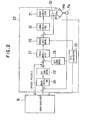
- Fig. 1 shows a control section of an injection-molding machine for executing a method of controlling switching from pressure holding to metering and kneading according to an embodiment of the invention.
- 1 is a numerical control unit for controlling the injection-molding machine.
- the numerical control unit 1 comprises a numerical control microprocessor (hereinafter referred to as NC CPU) 11, and a microprocessor (hereinafter referred to as PMC CPU) 12 for controlling a programmable machine controller, not shown.
- NC CPU numerical control microprocessor
- PMC CPU microprocessor
- Connected to the NC CPU 11 are a ROM 14 having stored therein a monitor program for generally controlling the injection-molding machine, and a RAM 15 for temporal storage of data.
- a servo-interface 18 Also connected to the NC CPU 11 through a servo-interface 18 are servo circuits for drivingly controlling servomotors for respective clamp shaft, ejector shaft, injection shaft and screw rotating shaft.
- Fig. 1 shows only servomotors Ma, Mb for the respective injection shaft and screw rotating shaft, and servo circuits 23, 24 associated respectively with both the motors.
- a ROM 16 having stored therein a sequence program for use in execution of various kinds of operations of the injection-molding machine subsequently to be described, and a RAM 17 for temporal storage of data.
- 19 is a nonvolatile shared RAM having a back-up power source.
- the RAM 19 is adapted to store an NC program for use in control of various kinds of operations of the injection-molding machine, various kinds of set values, parameters and the like.
- 13 is a bus-arbiter controller (hereinafter referred to as BAC).
- BAC 13 bus-arbiter controller
- Connected to the BAC 13 through respective buses are the NC CPU 11, the PMC CPU 12, the shared RAM 19, an input circuit 20, and an output circuit 21.
- the BAC 13 is adapted to selectively permit the use of the buses by both the CPUs 11, 12.
- a data input unit with display (hereinafter referred to as CRT/MDI) 2 is serially connected to the BAC 13 through an operator panel controller 22.
- the reference character Pa denotes a pulse encoder which is coupled to the injection shaft servomotor Ma and which outputs pulses with rotation of the motor, i.e., axial movement of a screw, not shown.
- the servo circuit 23 comprises an error register 25 which is operative in response to a command pulse for axially moving the screw, supplied from the NC CPU 11 through the servo-interface 18, and a pulse output from the pulse encoder Pa, to store a current deviation between a command screw position and an actual screw position.
- a D/A converter 26 for converting the stored value of the error register 25 into an analog speed command voltage is arranged at the subsequent stage of the error register 25 such that an added voltage of this speed command voltage and an offset voltage (to be described later) from the servo-interface 18 is applied to a noninverting input terminal of an error amplifier 27.
- An inverting input terminal of the amplifier 27 is connected to an F/V converter 28 for converting the frequency of pulse train outputted from the pulse encoder Pa into a voltage representative of an actual screw moving speed, such that the amplifier 27 outputs a deviation between the above-mentioned added voltage and the actual speed voltage as an armature current command associated with the servomotor Ma.
- Torque limit means 29 for retaining back pressure applied to the screw to a set value is arranged at the subsequent stage of the error amplifier 27.
- the torque limit means 29 is adapted to be operative in response to a command from the PMC CPU 12 converted into an analog amount by a D/A converter 33, to limit the output of the amplifier 27 to a value equal to or lower than the level in accordance with the set back pressure.
- the numeral 30 denotes an error amplifier for amplifying an deviation between a driving current command supplied from the error amplifier 27 through the torque limit means 29 and an actual driving current detected by a current detector 32.
- the error amplifier 30 has its output side connected to a power
- the servo circuit 24 is arranged similarly to the servo circuit 23 except that the servo circuit 24 does not include an element corresponding to the torque limit means 29.
- First set by the CRT/MDI 2 are various kinds of set values such as a torque limit value for pressure holding, a pressure holding period of time, a torque limit value for metering and kneading, an axial position of the screw at completion of the metering and kneading, and the like. These set values are then stored respectively in predetermined address regions of the shared RAM 19. Subsequently, a series of injection molding operations consisting of various steps is executed in accordance with the NC program stored in the shared RAM 19.
- the NC CPU 11 initiates pulse distribution to the servo circuit 23 associated with the injection shaft servomotor Ma through the servo-interface 18. Specifically, the CPU 11 supplies the number of move command pulses required for moving the screw tip to the tip of the heating cylinder, to the error register 25 of the servo circuit 23. At this initiation of the pulse distribution, the CPU 11 writes an M code M H representative of "in the course of pressure holding", in the shared RAM 19 through the BAC 13 (step S1).
- the PMC CPU 12 detects that the M code M H has been written in the shared RAM 19 through the BAC 13, the PMC CPU 12 sets a pressure holding timer T H (step S2), and rewrites the torque limit value on the injection shaft stored in the RAM 19 to a higher torque limit value Tl for the pressure holding (step S3).
- the rewritten torque limit value is applied to the torque limit means 29 through the BAC 13, the NC CPU 11, the servo-interface 18 and the D/A converter 33 of the servo circuit 23.
- the screw Since, as described above, the move command sufficient that the screw tip reaches the heating cylinder tip is sent to the error register 25, the screw is driven for forward movement against the pressure of the resin filled in the mold at the injection step, by a higher output torque of the servomotor Ma in compliance with the above-mentioned torque limit value. Subsequently, as the screw reaches the axial position in short of the cylinder tip by the cushion amount, the driving force and the resin pressure balance with each other, so that the screw is retained at this position. As a result, the set hold pressure is applied to the resin.
- the PMC CPU 12 writes a servo-off signal SVF1 on the injection shaft, in the shared RAM 19 (step S5).
- the NC CPU 11 detects the servo-off signal SVF1
- the NC CPU 11 initiates follow-up of the error register 25, with injection shaft servomotor Ma excited. That is, the CPU 11 reads an error amount on the order equivalent to the cushion amount, stored in the error register 25, and effects such pulse distribution as to bring the error amount to "0".
- step S7 the CPU 11 writes a distribution end signal DEN in the shared RAM 19 (step S8).
- step S8 the PMC CPU 12 detects the distribution end signal DEN from the shared RAM 19 through the BAC 13
- the PMC CPU 12 erases the servo-off signal SVF1 written at the step S5 (step S9), and writes, in the shared RAM 19, an FIN signal representative of completion of the treatment associated with the M code M H indicative of "in the course of pressure holding" (step S10).
- the PMC CPU 12 rewrites the torque limit value on the injection shaft during the PMC sequence cycle for which writing of the FIN signal is effected, to a value T2 for the metering.
- the PMC CPU 12 again writes the servo-off signal SVF1 in the shared RAM, and erases the servo-off signal SVF1 during the next PMC sequence cycle. That is, the servo-off signal is written over a period of time required to follow up the error amount generated with rearward movement of the screw, here, over one PMC sequence cycle (step Sll).
- the NC CPU 11 detects, through the BAC 13, that the FIN signal is written in the shared RAM 19, the NC CPU 11 releases the M code M H (step S12), and follows up the error register 25 in a manner like that described above while the servo-off signal SVF1 is written (step S13).
- the screw moves rearwardly with reduction in the output torque of the servomotor Ma in attendance on the rewriting between the torque limits at the step Sll, in turn, with reduction in pressure acting upon the resin, so that the error amount is generated in the error register 25.
- pulse distribution is effected to the error register 25 so as to cancel this generated error amount. Therefore, no error amount is accumulated in the register 25 and, accordingly, the register does not overflow.
- step S14 the NC CPU 11 drives the screw rotating shaft servomotor Mb at a set rotational speed, through the servo-interface 18 and the servo circuit 24, and drives the injection shaft servomotor Ma through the servo-interface 18 and the servo circuit 23 in the following manner.
- the NC CPU 11 When the set back pressure is higher than friction force which is generated in a power transmission system, not shown, connecting the screw and the servomotor Ma to each other and which acts in the back pressure increasing direction, the NC CPU 11 does not apply the offset voltage to the error amplifier 27, but sends the torque limit command corresponding to a difference between the set back pressure and the friction force, to the torque limit means 29. Further, the CPU 11 outputs the move command to the error register 25 so as to retain the screw at the current position. Thereafter, as the molten resin increases in amount and the screw moves rearwardly under the resin pressure, a negative pulse is supplied from the pulse encoder Pa to the error register 25 so that the register value, i.e., the error amount representative of a difference between the command screw position and the actual screw position increases.
- the torque command is outputted from the error amplifier 27, for returning the screw to its initial position in response to the increase in the register value.
- the torque command is limited to a value equal to or lower than the torque limit value by the torque limit means 29 to which the torque limit value is applied from the CPU 11.
- the screw subjected to a resultant force (back pressure) of the friction force and the output from the servomotor Ma corresponding to the difference between the set back pressure and the friction force, applies the set back pressure to the resin.
- the NC CPU 11 reads the value of the error register 25 at a predetermined cycle, and performs pulse distribution so as to bring the register value to zero. That is, the NC CPU 11 follows up the register. However, in order to follow up the register, it is necessary to do requisite calculation on the basis of the detected register value, and then to effect pulse distribution in compliance with the calculation result. Accordingly, it takes time until the follow-up is completed. On the other hand, in the meantime, the resin pressure increases and the screw moves rearwardly. Therefore, in practice, the error register value is not brought to zero. After all, the torque command is always issued during metering, for driving the screw for forward movement.
- the NC CPU 11 which detects the screw current position with reference to an injection shaft current value register, not shown, each time of execution of the follow-up, detects arrival to the metering completion position, to interrupt rotation of the screw. As a result, the metering and kneading operation is completed.
- NC CPU 11 when the-set back pressure is lower than the friction force, NC CPU 11 outputs, to the error amplifier 27, an offset voltage (minus) acting to move the screw rearwardly, and outputs, to the torque limit means 29, a torque limit value corresponding to the difference between the friction force and the set back pressure.
- the torque command driving the servomotor Ma in the direction of rearward movement of the screw is applied from the error amplifier 27 to the torque limit means 29.
- the torque command is limited to a value corresponding to the difference between the friction force and the set back pressure.
Abstract
Description
- The present invention relates to a switching control method which can smoothly effect transfer from a pressure holding step to a metering and kneading step in an injection-molding machine employing a servomotor as an injection shaft driving source.
- An injection-molding machine comprises an injection shaft driving source for axially driving a screw, and operates in such a manner that the screw is driven for forward movement to inject molten resin into a mold, and a hold pressure lower than the injection pressure and acting in the same direction is then applied to the screw. In the injection-molding machine which employs the servomotor as the injection shaft driving source and which comprises a numerical control unit including a servo circuit for driving the servomotor, typically, a move command sufficient that the tip of the screw reaches a tip of a heating cylinder is sent to the servo circuit to generate the hold pressure. That is, the screw is driven for forward movement by axially driving force in accordance with the move command and, subsequently, the screw is retained at an axial position in short of the cylinder tip position by a cushion amount, where the axial driving force balances with pressure of the molten resin filled in the mold, to apply the hold pressure to the resin. At the subsequent metering and kneading step, axial pressure, i.e., back pressure lower than the hold pressure and acting in the advance direction is applied to the screw while rotating the latter, to effect metering and kneading.
- At transfer from the pressure holding step to the metering and kneading step, the molten resin slightly expands in volume due to differential pressure between the hold pressure and the back pressure, and the screw moves rearwardly in response to the differential pressure. At this time, an error amount equal to an added value of the cushion amount and the amount of rearward movement of the screw is accumulated in an error register of the servo circuit. As the error amount exceeds the register capacity, the error register overflows and, in response thereto, the typical numerical control unit generates an alarm and operates so as to interrupt operation of the injection-molding machine. It is inconvenient that the injection-molding machine stops in operation during execution of the usual injection molding cycle. Additionally, as is publicly known conventionally, even if transfer is made to the metering and kneading step after follow-up of the error register at completion of the pressure holding step so as to bring the error amount accumulated in the error register and equivalent to the cushion amount, to "0", similar inconvenience is caused if the amount of rearward movement of the screw is large.
- It is, therefore, an object of the invention to prevent overflow of an error register within a servo circuit at transfer from a pressure holding step to a metering and kneading step, to thereby prevent interruption of operation of an injection-molding machine.
- In order to achieve the above-mentioned object, a method of controlling switching from pressure holding to metering and kneading, according to the invention, in an injection-molding machine which employs a servomotor as an injection shaft driving source for axially driving a screw and which drives the servomotor through a servo circuit having an error register to apply back pressure during injection, during pressure holding and during metering and kneading, comprises the steps of reducing an error amount accumulated in the error register to such a predetermined value that the register does not overflow at completion of a pressure holding step, switching a value of torque limit acting on the servomotor from a set value for the pressure holding to a set value for the metering and kneading, reducing the error amount of the error register to a value equal to or lower than the predetermined value over a predetermined period of time from execution of the switching, and then transferring to a metering and kneading step.
- In this manner, the invention is arranged such that the error amount accumulated in the error register is reduced at completion of the pressure holding while output torque of the injection shaft servomotor is retained to a value at the pressure holding, the value of the torque limit acting on the servomotor is then altered from the value for the pressure holding to the value for the metering, and the error amount of the error register is reduced. With such arrangement, even if the screw moves rearwardly under reaction force from the resin at reduction in the output torque of the injection shaft servomotor in response to the alteration of the torque limit value so that the error amount is generated within the error register, the error amount is not accumulated within the error register, so that overflow of the error register, in turn, interruption of operation of the injection-molding machine does not occur.
-
- Fig. 1 is a diagrammatic block circuit diagram showing an essential portion of an injection-molding machine to which a switching control method according to an embodiment of the invention is applied;
- Fig. 2 is a block circuit diagram showing in detail an injection shaft servo circuit illustrated in Fig. 1; and
- Fig. 3 is a flow chart of a control program for switching from pressure holding to metering and kneading, which is executed by a numerical control unit illustrated in Fig. 1.
- Fig. 1 shows a control section of an injection-molding machine for executing a method of controlling switching from pressure holding to metering and kneading according to an embodiment of the invention. In the figure, 1 is a numerical control unit for controlling the injection-molding machine. The numerical control unit 1 comprises a numerical control microprocessor (hereinafter referred to as NC CPU) 11, and a microprocessor (hereinafter referred to as PMC CPU) 12 for controlling a programmable machine controller, not shown. Connected to the NC
CPU 11 are aROM 14 having stored therein a monitor program for generally controlling the injection-molding machine, and aRAM 15 for temporal storage of data. Also connected to the NCCPU 11 through a servo-interface 18 are servo circuits for drivingly controlling servomotors for respective clamp shaft, ejector shaft, injection shaft and screw rotating shaft. Fig. 1 shows only servomotors Ma, Mb for the respective injection shaft and screw rotating shaft, andservo circuits - Connected to the
PMC CPU 12 are aROM 16 having stored therein a sequence program for use in execution of various kinds of operations of the injection-molding machine subsequently to be described, and aRAM 17 for temporal storage of data. 19 is a nonvolatile shared RAM having a back-up power source. TheRAM 19 is adapted to store an NC program for use in control of various kinds of operations of the injection-molding machine, various kinds of set values, parameters and the like. 13 is a bus-arbiter controller (hereinafter referred to as BAC). Connected to theBAC 13 through respective buses are theNC CPU 11, thePMC CPU 12, the sharedRAM 19, aninput circuit 20, and anoutput circuit 21. The BAC 13 is adapted to selectively permit the use of the buses by both theCPUs BAC 13 through anoperator panel controller 22. - The
servo circuit 23 and its peripheral elements will next be described further with reference to Fig. 2. In Fig. 2, the reference character Pa denotes a pulse encoder which is coupled to the injection shaft servomotor Ma and which outputs pulses with rotation of the motor, i.e., axial movement of a screw, not shown. - The
servo circuit 23 comprises anerror register 25 which is operative in response to a command pulse for axially moving the screw, supplied from theNC CPU 11 through the servo-interface 18, and a pulse output from the pulse encoder Pa, to store a current deviation between a command screw position and an actual screw position. A D/A converter 26 for converting the stored value of theerror register 25 into an analog speed command voltage is arranged at the subsequent stage of theerror register 25 such that an added voltage of this speed command voltage and an offset voltage (to be described later) from the servo-interface 18 is applied to a noninverting input terminal of anerror amplifier 27. An inverting input terminal of theamplifier 27 is connected to an F/V converter 28 for converting the frequency of pulse train outputted from the pulse encoder Pa into a voltage representative of an actual screw moving speed, such that theamplifier 27 outputs a deviation between the above-mentioned added voltage and the actual speed voltage as an armature current command associated with the servomotor Ma. Torque limit means 29 for retaining back pressure applied to the screw to a set value is arranged at the subsequent stage of theerror amplifier 27. The torque limit means 29 is adapted to be operative in response to a command from thePMC CPU 12 converted into an analog amount by a D/A converter 33, to limit the output of theamplifier 27 to a value equal to or lower than the level in accordance with the set back pressure. Thenumeral 30 denotes an error amplifier for amplifying an deviation between a driving current command supplied from theerror amplifier 27 through the torque limit means 29 and an actual driving current detected by acurrent detector 32. Theerror amplifier 30 has its output side connected to apower amplifier 31. - The
servo circuit 24 is arranged similarly to theservo circuit 23 except that theservo circuit 24 does not include an element corresponding to the torque limit means 29. - The operation of the apparatus according to the embodiment will next be described with reference to Fig. 3.
- First set by the CRT/MDI 2 are various kinds of set values such as a torque limit value for pressure holding, a pressure holding period of time, a torque limit value for metering and kneading, an axial position of the screw at completion of the metering and kneading, and the like. These set values are then stored respectively in predetermined address regions of the shared
RAM 19. Subsequently, a series of injection molding operations consisting of various steps is executed in accordance with the NC program stored in the sharedRAM 19. - In the pressure holding step, the NC
CPU 11 initiates pulse distribution to theservo circuit 23 associated with the injection shaft servomotor Ma through the servo-interface 18. Specifically, theCPU 11 supplies the number of move command pulses required for moving the screw tip to the tip of the heating cylinder, to theerror register 25 of theservo circuit 23. At this initiation of the pulse distribution, theCPU 11 writes an M code MH representative of "in the course of pressure holding", in the sharedRAM 19 through the BAC 13 (step S1). As thePMC CPU 12 detects that the M code MH has been written in the sharedRAM 19 through theBAC 13, thePMC CPU 12 sets a pressure holding timer TH (step S2), and rewrites the torque limit value on the injection shaft stored in theRAM 19 to a higher torque limit value Tl for the pressure holding (step S3). The rewritten torque limit value is applied to the torque limit means 29 through theBAC 13, theNC CPU 11, the servo-interface 18 and the D/A converter 33 of theservo circuit 23. - Since, as described above, the move command sufficient that the screw tip reaches the heating cylinder tip is sent to the
error register 25, the screw is driven for forward movement against the pressure of the resin filled in the mold at the injection step, by a higher output torque of the servomotor Ma in compliance with the above-mentioned torque limit value. Subsequently, as the screw reaches the axial position in short of the cylinder tip by the cushion amount, the driving force and the resin pressure balance with each other, so that the screw is retained at this position. As a result, the set hold pressure is applied to the resin. - Subsequently, as the pressure holding period of time expires, that is, as the period of time set by the pressure holding timer TH expires (step S4), the
PMC CPU 12 writes a servo-off signal SVF1 on the injection shaft, in the shared RAM 19 (step S5). As the NCCPU 11 detects the servo-off signal SVF1, theNC CPU 11 initiates follow-up of theerror register 25, with injection shaft servomotor Ma excited. That is, theCPU 11 reads an error amount on the order equivalent to the cushion amount, stored in theerror register 25, and effects such pulse distribution as to bring the error amount to "0". Subsequently, as the error amount of theerror register 25 is brought to "0" (step S7), theCPU 11 writes a distribution end signal DEN in the shared RAM 19 (step S8). As thePMC CPU 12 detects the distribution end signal DEN from the sharedRAM 19 through theBAC 13, thePMC CPU 12 erases the servo-off signal SVF1 written at the step S5 (step S9), and writes, in the sharedRAM 19, an FIN signal representative of completion of the treatment associated with the M code MH indicative of "in the course of pressure holding" (step S10). Subsequently, thePMC CPU 12 rewrites the torque limit value on the injection shaft during the PMC sequence cycle for which writing of the FIN signal is effected, to a value T2 for the metering. ThePMC CPU 12 again writes the servo-off signal SVF1 in the shared RAM, and erases the servo-off signal SVF1 during the next PMC sequence cycle. That is, the servo-off signal is written over a period of time required to follow up the error amount generated with rearward movement of the screw, here, over one PMC sequence cycle (step Sll). - On the other hand, as the
NC CPU 11 detects, through theBAC 13, that the FIN signal is written in the sharedRAM 19, theNC CPU 11 releases the M code MH (step S12), and follows up theerror register 25 in a manner like that described above while the servo-off signal SVF1 is written (step S13). As a result, the screw moves rearwardly with reduction in the output torque of the servomotor Ma in attendance on the rewriting between the torque limits at the step Sll, in turn, with reduction in pressure acting upon the resin, so that the error amount is generated in theerror register 25. Nevertheless, pulse distribution is effected to theerror register 25 so as to cancel this generated error amount. Therefore, no error amount is accumulated in theregister 25 and, accordingly, the register does not overflow. - Subsequently, the program proceeds to the metering and kneading step (step S14) where the
NC CPU 11 drives the screw rotating shaft servomotor Mb at a set rotational speed, through the servo-interface 18 and theservo circuit 24, and drives the injection shaft servomotor Ma through the servo-interface 18 and theservo circuit 23 in the following manner. - When the set back pressure is higher than friction force which is generated in a power transmission system, not shown, connecting the screw and the servomotor Ma to each other and which acts in the back pressure increasing direction, the
NC CPU 11 does not apply the offset voltage to theerror amplifier 27, but sends the torque limit command corresponding to a difference between the set back pressure and the friction force, to the torque limit means 29. Further, theCPU 11 outputs the move command to theerror register 25 so as to retain the screw at the current position. Thereafter, as the molten resin increases in amount and the screw moves rearwardly under the resin pressure, a negative pulse is supplied from the pulse encoder Pa to theerror register 25 so that the register value, i.e., the error amount representative of a difference between the command screw position and the actual screw position increases. The torque command is outputted from theerror amplifier 27, for returning the screw to its initial position in response to the increase in the register value. The torque command is limited to a value equal to or lower than the torque limit value by the torque limit means 29 to which the torque limit value is applied from theCPU 11. As a result, the screw, subjected to a resultant force (back pressure) of the friction force and the output from the servomotor Ma corresponding to the difference between the set back pressure and the friction force, applies the set back pressure to the resin. - During metering, the
NC CPU 11 reads the value of theerror register 25 at a predetermined cycle, and performs pulse distribution so as to bring the register value to zero. That is, theNC CPU 11 follows up the register. However, in order to follow up the register, it is necessary to do requisite calculation on the basis of the detected register value, and then to effect pulse distribution in compliance with the calculation result. Accordingly, it takes time until the follow-up is completed. On the other hand, in the meantime, the resin pressure increases and the screw moves rearwardly. Therefore, in practice, the error register value is not brought to zero. After all, the torque command is always issued during metering, for driving the screw for forward movement. In this manner, as the screw moves rearwardly to the metering completion position while applying the set back pressure to the resin, theNC CPU 11, which detects the screw current position with reference to an injection shaft current value register, not shown, each time of execution of the follow-up, detects arrival to the metering completion position, to interrupt rotation of the screw. As a result, the metering and kneading operation is completed. - On the other hand, when the-set back pressure is lower than the friction force,
NC CPU 11 outputs, to theerror amplifier 27, an offset voltage (minus) acting to move the screw rearwardly, and outputs, to the torque limit means 29, a torque limit value corresponding to the difference between the friction force and the set back pressure. As a result, the torque command driving the servomotor Ma in the direction of rearward movement of the screw is applied from theerror amplifier 27 to the torque limit means 29. By themeans 29, the torque command is limited to a value corresponding to the difference between the friction force and the set back pressure. As the screw moves rearwardly during metering and kneading, the friction force generated in the power transmitting system acts to prevent rearward movement of the screw, while the output from the servomotor Ma acts to promote rearward movement of the screw. After all, the set back pressure is applied to the resin. Thereafter, metering and kneading are effected in a manner like that described above.
Claims (2)
Applications Claiming Priority (3)
| Application Number | Priority Date | Filing Date | Title |
|---|---|---|---|
| JP61172823A JPS6330226A (en) | 1986-07-24 | 1986-07-24 | Control method of changeover from dwell to measurement |
| JP172823/86 | 1986-07-24 | ||
| PCT/JP1987/000541 WO1988000518A1 (en) | 1986-07-24 | 1987-07-24 | Method of switching from dwelling step to metering/kneading step |
Publications (4)
| Publication Number | Publication Date |
|---|---|
| EP0280734A1 true EP0280734A1 (en) | 1988-09-07 |
| EP0280734A4 EP0280734A4 (en) | 1990-01-08 |
| EP0280734B1 EP0280734B1 (en) | 1992-04-15 |
| EP0280734B2 EP0280734B2 (en) | 1995-01-25 |
Family
ID=15949026
Family Applications (1)
| Application Number | Title | Priority Date | Filing Date |
|---|---|---|---|
| EP87904939A Expired - Lifetime EP0280734B2 (en) | 1986-07-24 | 1987-07-24 | Method of controlling the switching from dwelling step to metering/kneading step |
Country Status (5)
| Country | Link |
|---|---|
| US (1) | US4842801A (en) |
| EP (1) | EP0280734B2 (en) |
| JP (1) | JPS6330226A (en) |
| DE (1) | DE3778344D1 (en) |
| WO (1) | WO1988000518A1 (en) |
Cited By (1)
| Publication number | Priority date | Publication date | Assignee | Title |
|---|---|---|---|---|
| DE4314722C1 (en) * | 1993-04-05 | 1994-04-28 | Procontrol Ag Flawil | Injection moudling machine with electric motor drive and process control - involves limiting various parameters and using a speed signal as adjustable variable for initiating axial screw movement |
Families Citing this family (5)
| Publication number | Priority date | Publication date | Assignee | Title |
|---|---|---|---|---|
| JP2652275B2 (en) * | 1991-02-06 | 1997-09-10 | ファナック株式会社 | Injection, holding pressure, back pressure control method for electric injection molding machine |
| CA2142754C (en) * | 1994-05-20 | 1999-04-13 | Thomas H. Richards | Clamp control for injection molding machine |
| US5456870A (en) * | 1994-05-20 | 1995-10-10 | Van Dorn Demag Corporation | Barrel temperature state controller for injection molding machine |
| JP2805189B2 (en) * | 1994-11-10 | 1998-09-30 | 日精樹脂工業株式会社 | Injection molding machine |
| US7010233B2 (en) * | 2001-12-07 | 2006-03-07 | Transmode Systems Ab | Interface device for a fiberoptic communication network and methods of using such a device |
Citations (2)
| Publication number | Priority date | Publication date | Assignee | Title |
|---|---|---|---|---|
| US3666141A (en) * | 1970-05-25 | 1972-05-30 | Cincinnati Milacron Inc | Method and apparatus for iterative control of shot size and cushion size |
| EP0080375A2 (en) * | 1981-11-25 | 1983-06-01 | Fanuc Ltd. | Method and apparatus for sensing current position in position control system |
Family Cites Families (8)
| Publication number | Priority date | Publication date | Assignee | Title |
|---|---|---|---|---|
| JPS58139201A (en) * | 1982-02-12 | 1983-08-18 | Toyota Central Res & Dev Lab Inc | Failure detector for servo system |
| JPS60262616A (en) * | 1984-06-11 | 1985-12-26 | Fanuc Ltd | Kneading system in injection molding machine |
| JPS6161820A (en) * | 1984-09-04 | 1986-03-29 | Fanuc Ltd | Pressure retaining system of injection molding machine |
| JPS6161818A (en) * | 1984-09-04 | 1986-03-29 | Fanuc Ltd | Control system of rotation of screw in injection molding machine |
| JPS61114834A (en) * | 1984-11-09 | 1986-06-02 | Fanuc Ltd | System of protecting mold of injection molding machine using servomotor |
| JPS61220817A (en) * | 1985-03-28 | 1986-10-01 | Fanuc Ltd | Measuring and kneading system for injection molding machine |
| JPH0773861B2 (en) * | 1985-04-26 | 1995-08-09 | ファナック株式会社 | Drive control method for injection molding machine driven by servo motor |
| JPS61249724A (en) * | 1985-04-30 | 1986-11-06 | Fanuc Ltd | Changeover control method for unit quantity of torque limiting value of servomotor for injection molding machine |
-
1986
- 1986-07-24 JP JP61172823A patent/JPS6330226A/en active Granted
-
1987
- 1987-07-24 EP EP87904939A patent/EP0280734B2/en not_active Expired - Lifetime
- 1987-07-24 WO PCT/JP1987/000541 patent/WO1988000518A1/en active IP Right Grant
- 1987-07-24 US US07/175,000 patent/US4842801A/en not_active Expired - Lifetime
- 1987-07-24 DE DE8787904939T patent/DE3778344D1/en not_active Expired - Lifetime
Patent Citations (2)
| Publication number | Priority date | Publication date | Assignee | Title |
|---|---|---|---|---|
| US3666141A (en) * | 1970-05-25 | 1972-05-30 | Cincinnati Milacron Inc | Method and apparatus for iterative control of shot size and cushion size |
| EP0080375A2 (en) * | 1981-11-25 | 1983-06-01 | Fanuc Ltd. | Method and apparatus for sensing current position in position control system |
Non-Patent Citations (1)
| Title |
|---|
| See also references of WO8800518A1 * |
Cited By (1)
| Publication number | Priority date | Publication date | Assignee | Title |
|---|---|---|---|---|
| DE4314722C1 (en) * | 1993-04-05 | 1994-04-28 | Procontrol Ag Flawil | Injection moudling machine with electric motor drive and process control - involves limiting various parameters and using a speed signal as adjustable variable for initiating axial screw movement |
Also Published As
| Publication number | Publication date |
|---|---|
| WO1988000518A1 (en) | 1988-01-28 |
| US4842801A (en) | 1989-06-27 |
| EP0280734B2 (en) | 1995-01-25 |
| JPS6330226A (en) | 1988-02-08 |
| EP0280734B1 (en) | 1992-04-15 |
| EP0280734A4 (en) | 1990-01-08 |
| JPH0473687B2 (en) | 1992-11-24 |
| DE3778344D1 (en) | 1992-05-21 |
Similar Documents
| Publication | Publication Date | Title |
|---|---|---|
| KR960016026B1 (en) | Method for automatically adjusting die thickness in toggle type lock | |
| KR970002297B1 (en) | Back pressure control method and apparatus for electric injection molding machine | |
| JPS61248719A (en) | Control system for driving of injection molding machine driven by servomotor | |
| EP0276324B1 (en) | Suck-back method in an injection molding machine | |
| US4816196A (en) | Method and apparatus for effecting injection control of an injection-molding machine | |
| US4842801A (en) | Method of controlling switching from pressure holding to metering and kneading | |
| US4970447A (en) | Software servo control apparatus for use in an injection molding machine | |
| EP0300053A1 (en) | Method of controlling injection motor of injection molding machine | |
| EP0249641B1 (en) | Metering method in an injection molding machine | |
| EP0245521A1 (en) | Injection molding machine and method of controlling back pressure thereof | |
| KR960015302B1 (en) | Method of controlling injection of an electrically driven injection molding machine | |
| JPH0255216B2 (en) | ||
| JP3366921B2 (en) | Compression molding control method | |
| JPH082574B2 (en) | Compression molding control method in electric injection molding machine | |
| JP2759888B2 (en) | Switching control method from holding pressure to weighing | |
| JP3096944B2 (en) | Injection control method for injection molding machine and injection molding machine | |
| JPH085102B2 (en) | Screw protection method | |
| JP2525727B2 (en) | Injection molding method | |
| JP2640680B2 (en) | Multi-stage control method of dwelling speed | |
| EP0321585B1 (en) | Device for detecting the most advanced position of screw | |
| JPH09174638A (en) | Force feedback control method for injection molding machine | |
| JPH07119035B2 (en) | Holding pressure control method of electric injection molding machine | |
| JPH04244824A (en) | Dwell control method in electric injection molding machine |
Legal Events
| Date | Code | Title | Description |
|---|---|---|---|
| PUAI | Public reference made under article 153(3) epc to a published international application that has entered the european phase |
Free format text: ORIGINAL CODE: 0009012 |
|
| 17P | Request for examination filed |
Effective date: 19880226 |
|
| AK | Designated contracting states |
Kind code of ref document: A1 Designated state(s): DE FR GB |
|
| A4 | Supplementary search report drawn up and despatched |
Effective date: 19900108 |
|
| 17Q | First examination report despatched |
Effective date: 19910213 |
|
| GRAA | (expected) grant |
Free format text: ORIGINAL CODE: 0009210 |
|
| AK | Designated contracting states |
Kind code of ref document: B1 Designated state(s): DE FR GB |
|
| REF | Corresponds to: |
Ref document number: 3778344 Country of ref document: DE Date of ref document: 19920521 |
|
| ET | Fr: translation filed | ||
| PLBI | Opposition filed |
Free format text: ORIGINAL CODE: 0009260 |
|
| 26 | Opposition filed |
Opponent name: BATTENFELD GMBH Effective date: 19930114 |
|
| PG25 | Lapsed in a contracting state [announced via postgrant information from national office to epo] |
Ref country code: FR Effective date: 19930331 |
|
| REG | Reference to a national code |
Ref country code: FR Ref legal event code: ST |
|
| PUAH | Patent maintained in amended form |
Free format text: ORIGINAL CODE: 0009272 |
|
| STAA | Information on the status of an ep patent application or granted ep patent |
Free format text: STATUS: PATENT MAINTAINED AS AMENDED |
|
| 27A | Patent maintained in amended form |
Effective date: 19950125 |
|
| AK | Designated contracting states |
Kind code of ref document: B2 Designated state(s): DE FR GB |
|
| EN3 | Fr: translation not filed ** decision concerning opposition | ||
| PGFP | Annual fee paid to national office [announced via postgrant information from national office to epo] |
Ref country code: GB Payment date: 19980715 Year of fee payment: 12 |
|
| PG25 | Lapsed in a contracting state [announced via postgrant information from national office to epo] |
Ref country code: GB Free format text: LAPSE BECAUSE OF NON-PAYMENT OF DUE FEES Effective date: 19990724 |
|
| GBPC | Gb: european patent ceased through non-payment of renewal fee |
Effective date: 19990724 |
|
| PGFP | Annual fee paid to national office [announced via postgrant information from national office to epo] |
Ref country code: DE Payment date: 20000724 Year of fee payment: 14 |
|
| PG25 | Lapsed in a contracting state [announced via postgrant information from national office to epo] |
Ref country code: DE Free format text: LAPSE BECAUSE OF NON-PAYMENT OF DUE FEES Effective date: 20020501 |