EP0280244A2 - Dispositif et méthode d'alimentation de feuilles à une machine à assembler - Google Patents
Dispositif et méthode d'alimentation de feuilles à une machine à assembler Download PDFInfo
- Publication number
- EP0280244A2 EP0280244A2 EP88102585A EP88102585A EP0280244A2 EP 0280244 A2 EP0280244 A2 EP 0280244A2 EP 88102585 A EP88102585 A EP 88102585A EP 88102585 A EP88102585 A EP 88102585A EP 0280244 A2 EP0280244 A2 EP 0280244A2
- Authority
- EP
- European Patent Office
- Prior art keywords
- sheets
- hopper
- conveyor
- sheet
- reclining
- Prior art date
- Legal status (The legal status is an assumption and is not a legal conclusion. Google has not performed a legal analysis and makes no representation as to the accuracy of the status listed.)
- Withdrawn
Links
Images
Classifications
-
- B—PERFORMING OPERATIONS; TRANSPORTING
- B65—CONVEYING; PACKING; STORING; HANDLING THIN OR FILAMENTARY MATERIAL
- B65H—HANDLING THIN OR FILAMENTARY MATERIAL, e.g. SHEETS, WEBS, CABLES
- B65H29/00—Delivering or advancing articles from machines; Advancing articles to or into piles
- B65H29/12—Delivering or advancing articles from machines; Advancing articles to or into piles by means of the nip between two, or between two sets of, moving tapes or bands or rollers
- B65H29/14—Delivering or advancing articles from machines; Advancing articles to or into piles by means of the nip between two, or between two sets of, moving tapes or bands or rollers and introducing into a pile
-
- B—PERFORMING OPERATIONS; TRANSPORTING
- B65—CONVEYING; PACKING; STORING; HANDLING THIN OR FILAMENTARY MATERIAL
- B65H—HANDLING THIN OR FILAMENTARY MATERIAL, e.g. SHEETS, WEBS, CABLES
- B65H29/00—Delivering or advancing articles from machines; Advancing articles to or into piles
- B65H29/20—Delivering or advancing articles from machines; Advancing articles to or into piles by contact with rotating friction members, e.g. rollers, brushes, or cylinders
- B65H29/22—Delivering or advancing articles from machines; Advancing articles to or into piles by contact with rotating friction members, e.g. rollers, brushes, or cylinders and introducing into a pile
-
- B—PERFORMING OPERATIONS; TRANSPORTING
- B65—CONVEYING; PACKING; STORING; HANDLING THIN OR FILAMENTARY MATERIAL
- B65H—HANDLING THIN OR FILAMENTARY MATERIAL, e.g. SHEETS, WEBS, CABLES
- B65H2301/00—Handling processes for sheets or webs
- B65H2301/30—Orientation, displacement, position of the handled material
- B65H2301/32—Orientation of handled material
- B65H2301/321—Standing on edge
Definitions
- This invention relates to apparatus and method for feeding sheets to a sheet gatherer in the graphic arts industry.
- the graphic arts industry is concerned with the function of feeding or moving printed sheets or signatures from a stack or collection thereof and into a gathering apparatus so that the sheets can be collated.
- the present day popular way of accomplishing that function is to position a bundle of the sheets in a location adjacent a gatherer, and then to strip the sheets from the bundle in a shingled form and direct that shingled stream of sheets into the hopper of a feeder of those sheets. That prior art arrangement is shown in US-A-3 522 943 and US-A-3 982 749, by way of general examples.
- the sheets In that instance, the sheets must be taken from the initial bundle and positioned into a stream relationship, and the sheets are then again stacked in the desired quantity in the feeder hopper which requires that the sheets be positioned therein in only certain quantities, and thus the entire initial bundle cannot be placed into the hopper, but the stream feed is resorted to.
- the present invention provides for apparatus and method for properly loading the hopper, but to do so without the require ment of placing the sheets into an initial stream prior to recollecting them into a stack in the hopper.
- the present invention improves upon the prior art in that it does not require that the sheets be placed into a stream of shingled sheets, but, instead, the sheets can be moved from the initial bundle and directly into the hopper while the sheets remain basically in their side-by-side relationship.
- the advantage of the present invention is particularly appreciated when dealing with certain stock of sheet which does not shingle well, or when dealing with a great number of pages in each signature in the original stack, and, again, the signatures then do not accurately and easily enter into a shingled stream of signatures.
- the present invention improves upon the prior art in providing for an improved method and apparatus for feeding sheets into a gatherer, such as the hopper of the gatherer, and to do so by moving the sheets directly from the initial bundle and into the hopper, without intervening apparatus or requirements for shingling or the like.
- sheets are therefore placed within the control of a conveyor which receives the initial stack of sheets and which continuously moves into a downwardly directed orientation to place the sheets into a reclining orientation in the hopper of the gatherer, all in an accurate and desirable manner of both alignment and quantity required by the gatherer.
- the apparatus of the present invention is of a simplified construction, compared to the requirements of the prior art, but yet the present inventive apparatus is reliable and sturdy and is automatically controlled in feeding the sheets into the hopper in accordance with the automatic detection of the requirements of the hopper. Still further, the present apparatus and method provide for accommodating sheets of different widths and different types of stock and stacking requirements, and thus the present invention is versatile and highly desirable for the function of loading sheets into the hopper of a gatherer.
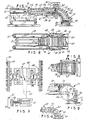
- FIGs. 1 and 2 show one embodiment of the apparatus where a table 10 is shown suitably supported, such as on a platform or a floor 11, then two spaced-apart stack side supports, such as the support 12 extend along opposite sides of the table 10.
- a stack of signatures 13 is supported on the table top 14 and between two of the uprightly extending and spaced-apart side supports 12 which are like sidewalls on opposite flanks of the stack 13.
- the two stationary members 12 have bristles or the like, as described in connection with other members hereinafter, for engaging the opposite sides of the stack 13 and thereby have the stack 13 remain in the upright and edge standing position, as shown in Fig. 1.
- the stack 13 is positioned on the tabletop 14 by means of a robot, overhead crane, or any other apparatus or in any other manner.
- the support or table 10 also extends into a portion designated 16 which can suitably support horizontally extending conveyor belts 17, as shown in Fig. 2.
- endless belts 18 and 19 are supported on the table 10 and on opposite sides of the upstanding sheets or stack designated 21, and that being a stack which was previously positioned where the stack 13 is now shown and was then advanced to the position where the stack 21 is now shown.
- the belts 17 are endless belts and extend underneath the upstanding sheets or signatures, and the belts can move, and are preferrably powered in a direction to have the sheets move rightwardly, as viewed in Figs. 1 and 2.
- the belts 18 and 19 also move, such as in the direction arrows shown adjacent thereto, and therefore the belts 18 and 19 are disposed to engage the opposite edges 22 and 23, respectively, of the sheets or stack 21, and thus retain the sheets on their upstanding or edge standing position, as shown.
- the belts 18 and 19 have bristles 24 thereon and extending outwardly therefrom for engagement of the opposite sides or edges 22 and 23 of the upstanding sheets 21 to thus retain the sheets in the edge standing position shown.
- the bristles 24 extend into positions between adjacent ones of sheets 21, or the bristles 24 can flex and thereby press against the sheet edges 22 and 23 to retain the upstanding sheet position desired and shown.
- the belts 17 and the two belts 18 and 19 move in the direction of the arrows shown and at the same speed so that the sheets 21 are advanced rightwardly, as viewed in Figs. 1 and 2.
- the belts 18 and 19 form at least a portion of a sheet conveyor which is advancing the sheets toward the gatherer, to be described later.
- Fig. 1 further shows an upstanding pusher 26 which is disposed in line with the stack 13 and which extends downwardly to a fluid cylinder 27 supported on the bed 10.
- the cylinder 27 can move the pusher 26 rightwardly, to advance the stack 13 into the confines of the belts 17, 18, and 19, such as toward the position of the sheets designated 21.
- a detector 28, such as a photocell can be positioned on the table 10 and thus detect the absence of any sheets in the position of the sheets 21, and, the detector 28 can be suitably operatively connected with the fluid cylinder 27 to control the actuation of the cylinder 27 for advancing the pusher 26 rightwardly to thus load the sheets into the position of the sheets 21, as needed.
- Such arrangement could be through any conventional means of a photocell type of detector 28 and electric or pneumatic connections with the fluid cylinder 27.
- a drive motor 29 is suitably engaged with a driven roller 31 on which the belt 19 is trained, and a likewise driven roller 31 is on the table 10 for the belt 18, as shown in Fig. 2.
- the motor 29 will drive the two rollers 31 in the appropriate direction for advancing the belts 18 and 19, as shown by the arrows thereon, to thereby advance the sheets 21 rightwardly.
- the belt 17 can also be connected with the drive 29 so that uniform movement of those belts is achieved for control and rightward movement of the sheets 21.
- Another portion of the conveyor is arcuate and designated 32 and it extends directly off the first portion of the conveyors 18 and 19, as shown.
- the conveyor portion 32 is curved downwardly and, as shown, extends through a right angle or 90 degree downward curve, but any other angulation with respect to the horizontal orientation of the conveyors 18 and 19 could also be utilized.
- the portion 32 is shown to have two spaced-apart belts 33 and 34, again on opposite sides of the sheets of the stack 21, for engaging the opposite sides and thus controlling the sheets in a edge standing and radial orientation through the commencement of the downward turn and at least until the sheets are deposited in a flat or horizontal orientation designated 36 in the confines of a hopper 37 which leads into a conventional type of sheet gatherer.
- the two conveyor belts 33 and 34 are thus spaced-apart and are parallel to each other through portions designated 38, that is parallel to the sides designated 39 and 41 of the sheets 21. Again, there are rollers, this time in the form of tapered rollers 42 and 43 which are at the terminal ends of the respective belts 33 and 34 so that the belts can move endless and in the direction of the arrows adjacent the side portions 39 and 41, all for advancing the sheets 21 first horizontally and then downwardly into the horizontal orientation designated at 36.
- the first conveyor portion is designated 44, and it forms a continuous conveyor with the other portion 32, all so that the sheets are initially moved in a horizontal component or in a horizontal plane, and they are subsequently moved downwardly in an arcuate direction by means of the conveyor portion 32.
- the initial stack of sheets 13 need not be placed into a shingled arrangement for purposes of feeding the hopper 37, and, by appropriate sensing or detecting members, such as the detector 28 and a hopper sensor 46, the conveyor can be operated to supply the hopper 37 with the required sheets in the horizontal orientation 36.
- a sensor 46 is on the hopper 37 and senses the absence of sheets in the position designated 36, and that sensor 46 thus extends to the drive control 29 for controlling the motor or drive 29 and thereby operating the conveyor for advancing the sheets to the hopper 37.
- Figs. 1 and 2 The embodiment shown in Figs. 1 and 2 is that of a belt type of conveyor, and it may be provided with guide tracks, such as the track designated 47, which are adjacent the upper and lower edges of the belt in both portions 44 and 32.
- Fig. 3 shows an enlargement of one arrangement for the guide tracks 47.
- the fragment of the belt 19 is shown, along with its bristles 24 extending outwardly thereon, and angled members 48 are suitably affixed to the back of the belt 19 and extend into a slotted guide 49 for riding along the slot 51 of the guide 49 which is thus stationarily mounted on an upstanding support 52.
- the belt 19 can move endlessly over its rollers 31 while being guided in the stationary guides 49 when the belt 19 is in contact with the side of the sheets 21 and also when it is away from the sheets 21 on its return run to the point of beginning again.
- belt 18 would be similarly guided, and, belts 33 and 34 would also be similarly guided by means of the guides shown in Fig. 3 or by any other conventional guide means, such as shown in connection with an arcuately extending conveyor belt manufactured and sold by FLOMASTER DIVISION OF PORTEC INC. of Canon City, Colorado (print of the disclosure in this file).
- the belts forming this conveyor are suitably supported to present upstanding or vertical planes on opposite sides of the upstanding sheets, and the belts have irregularly or roughened or bristled or like faces presented to the edges of the sheets for holding the sheets in the position of either upstanding or reclining position, such as shown in the arcuate path on the portion 32.
- the side conveyor belts can also move toward and away from the sheets, such as by means of an adjustment connected with the support 52 shown in Fig. 3.
- a crank 53 has a threaded shaft 54 which is axially restrained by supports 56.
- the shaft 54 engages a nut at 57 which in turn is connected with the standard 52.
- the nut 57 upon rotation of the threaded shaft 54, the nut 57 will be displaced to either the left or the right, and thus the standard 52 will likewise be displaced for moving the belt toward or away from the sheets 21, as desired.
- Fig. 4 shows the conveyor to be in one continuous chain arrangement, and thus both the horizontal portion 58 and the downwardly curved portion 59 are on the same chain or conveyor and extend through the complete path as shown with the conveyor portions 44 and 32 in Fig. 1.
- the conveyor is thus comprised of side links 61 suitably joined together by a flexible chain member designated 62 which extends around the turnaround and tapered roller 63, as in connection with Fig. 1.
- the faces of the link 61 can be the irregular or roughened surfaces, such as having bristles thereon, all for presenting the roughened or bristled surfaces to the edges of the sheets 21, as previously described.
- Figs. 5 and 6 show a somehwat different apparatus and method in that the downwardly extending portion of the conveyor is comprised of a circular brush 64 rotatably mounted on a shaft 66 for rotation in the direction of the arrow shown thereon.
- the brush 64 is disposed at the turndown or arcuate portion of the conveyor coming off the horizontal conveyor run designated 67 which again could be the belts 18 and 19.
- the brush 64 has its bristles 68 extended toward the edges of the sheets designated 69 to thus support the sheets in their fanning or turning mode as they move from the upstanding edge position on the conveyor 67 and down to the horizontal orientation designated 71 in the hopper 72.
- the circular brush 64 it is preferred that at least two quarter portions of the circular brush 64 be blocked from touching the edges of the sheets 69, such as by the insulating stationary segment sheets 73 and 74 which are interposed between the brush bristle 68 and the sheet edges 76.
- the brush bristles 68 are in contact with the sheets edges 76 for guiding the sheets from the upstanding or vertical position and around to the reclining or horizontal orientation position in the hopper 72.
- the speed of rotation of the brush 64 would be suitable for coordinating the movement of the sheet 69 with respect to their movement under the influence of the conveyor 67, all so that the hopper 72 can be properly loaded with sheets, as needed.
- control rollers 31 and 42 could be provided with sprockets designated 78 for purposes of engaging cylindrical portions 79 on the backs of the belts or on the backs of the chain of Fig. 4.
- the belt portions 44 and 32 are shown to be drivingly interconnected through a drive box 81 which has the necessary conventional drive transmitters so that the belts 33 and 34 at their inner arcuate portions 82 will move at the linear speed of the horizontal displacement of the sheets as induced by the conveyor portion 44.
- the speed along the inner arcuate path 82 is at least as fast as the horizontal speed induced by the conveyor portion 44.
- the method will be movement and are then directed at an angle to that component, namely, downwardly in arcuate path and are placed into a horizontal orientation which of course may be inclining with respect to the horizontal as well as full horizontal orientation in the hoppers described.
- Fig. 3 shows the conveyors can be laterally adjusted to move toward and away from the sheet opposite sides.
- the standard 52 can be moved to have the surface 86 press against the backing strip 48 to have the bristles 24 move closer to the sheets.
- the sh ets all have lower edges 87, and the two opposite side edges 22, 23, and 39, 41, contiguous to the lower edges 87.
Landscapes
- Engineering & Computer Science (AREA)
- Mechanical Engineering (AREA)
- Sheets, Magazines, And Separation Thereof (AREA)
Applications Claiming Priority (2)
| Application Number | Priority Date | Filing Date | Title |
|---|---|---|---|
| US17550 | 1987-02-24 | ||
| US07/017,550 US4819929A (en) | 1987-02-24 | 1987-02-24 | Apparatus and method for feeding sheets to a sheet gatherer |
Publications (2)
| Publication Number | Publication Date |
|---|---|
| EP0280244A2 true EP0280244A2 (fr) | 1988-08-31 |
| EP0280244A3 EP0280244A3 (fr) | 1988-10-26 |
Family
ID=21783216
Family Applications (1)
| Application Number | Title | Priority Date | Filing Date |
|---|---|---|---|
| EP88102585A Withdrawn EP0280244A3 (fr) | 1987-02-24 | 1988-02-22 | Dispositif et méthode d'alimentation de feuilles à une machine à assembler |
Country Status (2)
| Country | Link |
|---|---|
| US (1) | US4819929A (fr) |
| EP (1) | EP0280244A3 (fr) |
Cited By (2)
| Publication number | Priority date | Publication date | Assignee | Title |
|---|---|---|---|---|
| US8247414B2 (en) | 2006-07-25 | 2012-08-21 | Cephalon, Inc. | Pyridizinone derivatives and the use thereof as H3 inhibitors |
| CN108792680A (zh) * | 2018-06-19 | 2018-11-13 | 武汉华星光电半导体显示技术有限公司 | 膜材取料设备 |
Families Citing this family (2)
| Publication number | Priority date | Publication date | Assignee | Title |
|---|---|---|---|---|
| US5213321A (en) * | 1991-08-13 | 1993-05-25 | Stobb Walter John | Hopper loader for transporting sheets in an edge-standing arrangement, and method therefor |
| US7172548B2 (en) * | 2001-03-29 | 2007-02-06 | Zsolt Design Engineering, Inc. | Cushioning conversion system and method |
Citations (2)
| Publication number | Priority date | Publication date | Assignee | Title |
|---|---|---|---|---|
| GB2047663A (en) * | 1979-04-26 | 1980-12-03 | Molins Ltd | Method and apparatus for handling blanks |
| DE8509218U1 (de) * | 1985-03-27 | 1985-05-09 | Peter Temming AG, 2208 Glückstadt | Stapelvorrichtung zum Stapeln von an Faltlinien endlos aneinandergereihten Papierblättern |
Family Cites Families (9)
| Publication number | Priority date | Publication date | Assignee | Title |
|---|---|---|---|---|
| US3522943A (en) * | 1968-03-27 | 1970-08-04 | Donnelley & Sons Co | Signature feeder for gathering machine |
| US3718217A (en) * | 1969-08-22 | 1973-02-27 | A Stobb | Apparatus for feeding signatures |
| US3680854A (en) * | 1970-08-27 | 1972-08-01 | Jones & Co Inc R A | Method and apparatus for feeding flat blanks to make boxes |
| US3858490A (en) * | 1973-02-27 | 1975-01-07 | Raymond A Heisler | Method for automatically feeding and erecting folded cartons |
| US3982749A (en) * | 1975-07-07 | 1976-09-28 | Stobb, Inc. | Signature feeder |
| US4364554A (en) * | 1981-01-26 | 1982-12-21 | Bell & Howell Company | Conveyor arrangement for mail sorting machines |
| US4531343A (en) * | 1981-10-14 | 1985-07-30 | World Color Press, Inc. | Machine and process for stacking and bundling flexible sheet material |
| IT8321765V0 (it) * | 1983-05-06 | 1983-05-06 | Omg Pessina Perobelli | Dispositivo caricatore di segnature e simili, applicabile a mettifogli per macchine per legatoria. |
| IT1175477B (it) * | 1984-04-09 | 1987-07-01 | Sitma | Caricatore di segnatura fogli e prodotti similari per alimentatori di macchine confezionatrici di macchine per legatoria e simili |
-
1987
- 1987-02-24 US US07/017,550 patent/US4819929A/en not_active Expired - Fee Related
-
1988
- 1988-02-22 EP EP88102585A patent/EP0280244A3/fr not_active Withdrawn
Patent Citations (2)
| Publication number | Priority date | Publication date | Assignee | Title |
|---|---|---|---|---|
| GB2047663A (en) * | 1979-04-26 | 1980-12-03 | Molins Ltd | Method and apparatus for handling blanks |
| DE8509218U1 (de) * | 1985-03-27 | 1985-05-09 | Peter Temming AG, 2208 Glückstadt | Stapelvorrichtung zum Stapeln von an Faltlinien endlos aneinandergereihten Papierblättern |
Cited By (2)
| Publication number | Priority date | Publication date | Assignee | Title |
|---|---|---|---|---|
| US8247414B2 (en) | 2006-07-25 | 2012-08-21 | Cephalon, Inc. | Pyridizinone derivatives and the use thereof as H3 inhibitors |
| CN108792680A (zh) * | 2018-06-19 | 2018-11-13 | 武汉华星光电半导体显示技术有限公司 | 膜材取料设备 |
Also Published As
| Publication number | Publication date |
|---|---|
| EP0280244A3 (fr) | 1988-10-26 |
| US4819929A (en) | 1989-04-11 |
Similar Documents
| Publication | Publication Date | Title |
|---|---|---|
| CA1323383C (fr) | Poste d'assemblage pour machine a inserer | |
| US5083769A (en) | Dual collating machine | |
| US4616815A (en) | Automatic stacking and folding apparatus | |
| US4784558A (en) | Apparatus for inverting and stacking folded box blanks made of sheet material | |
| US5244199A (en) | Stream feeding machine for holding and delivering signatures | |
| US3982749A (en) | Signature feeder | |
| EP0202507A2 (fr) | Transporteur d'assemblage | |
| JPS6123080A (ja) | 折丁を丁合いする方法並びに装置 | |
| US20080128983A1 (en) | Methods and systems for controlling the feeding of stacked sheet material | |
| EP0416490A2 (fr) | Appareil pour manipuler des imprimés | |
| AU6950896A (en) | Magazine apparatus and method for loading documents | |
| US7048111B2 (en) | Hopper loader apparatus and method | |
| CN1145874A (zh) | 分离堆叠的扁平物品的设备 | |
| US4522384A (en) | Machine for collating signatures in the saddle format | |
| GB2135978A (en) | Belt loader for signatures, sheets, magazines and similar articles, for loading the feeders of packaging machines, binding machines and the like | |
| EP0337315B1 (fr) | Dispositif et procédé de collationnement de cahiers pour livres, brochures et autres | |
| SU1607686A3 (ru) | Устройство дл формировани стапелей из гибких плоских изделий | |
| US6017028A (en) | Hopper loader having arced conveyor for forming an overlapping stream of signatures from a vertical stack | |
| US4819929A (en) | Apparatus and method for feeding sheets to a sheet gatherer | |
| US4198039A (en) | Signature cover folder feeder | |
| EP0773901B1 (fr) | Trieuse/empileuse de grande capacite | |
| US4903955A (en) | Document stacking apparatus | |
| US6467768B1 (en) | Method and apparatus for conveying generally flat articles | |
| EP0627376A1 (fr) | Dispositif perfectionné d'alimentation en cahiers pour ligne de reliure | |
| GB2108069A (en) | Book reject mechanism |
Legal Events
| Date | Code | Title | Description |
|---|---|---|---|
| PUAI | Public reference made under article 153(3) epc to a published international application that has entered the european phase |
Free format text: ORIGINAL CODE: 0009012 |
|
| AK | Designated contracting states |
Kind code of ref document: A2 Designated state(s): CH DE FR GB IT LI |
|
| PUAL | Search report despatched |
Free format text: ORIGINAL CODE: 0009013 |
|
| AK | Designated contracting states |
Kind code of ref document: A3 Designated state(s): CH DE FR GB IT LI |
|
| 17P | Request for examination filed |
Effective date: 19890102 |
|
| 17Q | First examination report despatched |
Effective date: 19900905 |
|
| STAA | Information on the status of an ep patent application or granted ep patent |
Free format text: STATUS: THE APPLICATION IS DEEMED TO BE WITHDRAWN |
|
| 18D | Application deemed to be withdrawn |
Effective date: 19910116 |