EP0280132B1 - Open-shed jacquard machine with a pulley train block-controlled with the aid of boards moving upwards and downwards - Google Patents
Open-shed jacquard machine with a pulley train block-controlled with the aid of boards moving upwards and downwards Download PDFInfo
- Publication number
- EP0280132B1 EP0280132B1 EP88102105A EP88102105A EP0280132B1 EP 0280132 B1 EP0280132 B1 EP 0280132B1 EP 88102105 A EP88102105 A EP 88102105A EP 88102105 A EP88102105 A EP 88102105A EP 0280132 B1 EP0280132 B1 EP 0280132B1
- Authority
- EP
- European Patent Office
- Prior art keywords
- jacquard machine
- machine according
- open shed
- shed jacquard
- strips
- Prior art date
- Legal status (The legal status is an assumption and is not a legal conclusion. Google has not performed a legal analysis and makes no representation as to the accuracy of the status listed.)
- Expired - Lifetime
Links
- 239000000725 suspension Substances 0.000 claims description 21
- 238000009941 weaving Methods 0.000 claims description 4
- 230000005540 biological transmission Effects 0.000 claims 1
- KJFBVJALEQWJBS-XUXIUFHCSA-N maribavir Chemical compound CC(C)NC1=NC2=CC(Cl)=C(Cl)C=C2N1[C@H]1O[C@@H](CO)[C@H](O)[C@@H]1O KJFBVJALEQWJBS-XUXIUFHCSA-N 0.000 claims 1
- 239000004744 fabric Substances 0.000 description 8
- 230000007704 transition Effects 0.000 description 5
- 238000005452 bending Methods 0.000 description 4
- 229910000831 Steel Inorganic materials 0.000 description 3
- 239000010959 steel Substances 0.000 description 3
- 238000006073 displacement reaction Methods 0.000 description 1
- 230000003993 interaction Effects 0.000 description 1
- 238000000059 patterning Methods 0.000 description 1
- BASFCYQUMIYNBI-UHFFFAOYSA-N platinum Chemical compound [Pt] BASFCYQUMIYNBI-UHFFFAOYSA-N 0.000 description 1
Images


Classifications
-
- D—TEXTILES; PAPER
- D03—WEAVING
- D03C—SHEDDING MECHANISMS; PATTERN CARDS OR CHAINS; PUNCHING OF CARDS; DESIGNING PATTERNS
- D03C3/00—Jacquards
- D03C3/12—Multiple-shed jacquards, i.e. jacquards which move warp threads to several different heights, e.g. for weaving pile fabrics
-
- D—TEXTILES; PAPER
- D03—WEAVING
- D03C—SHEDDING MECHANISMS; PATTERN CARDS OR CHAINS; PUNCHING OF CARDS; DESIGNING PATTERNS
- D03C3/00—Jacquards
- D03C3/24—Features common to jacquards of different types
Definitions
- Jacquard machines are used to weave figures in pile fabrics.
- the upper fabric and the lower fabric which face each other with their tops and which are connected by the pile warp threads during weaving.
- the pile warp threads can assume three positions during weaving, namely above the upper fabric, in the middle between the two basic fabrics or below the lower fabric. This is the jacquard machine that brings each pile warp thread into one of those positions before each shot.
- Belgian patent specification No. 894.283 describes a roller pulling device of an open-pocket jacquard machine, in which one end of the stockings on a circuit board and the other end on a movable suspension device, or at the same time the harness cords with an outer end on the harness and with the other Are attached to a fixed suspension device.
- the movable suspension device consists of up and down movable boards on which the ends of one or more strings are fastened, so that those ends can be controlled in blocks, following a specific repeat.
- roller pulling device takes over the advantages of the open-pocket jacquard machine with roller pulling elements, avoids the disadvantage that two boards have to be used for each point controlled, and permits maximum patterning options with the smallest space requirement.
- the jacquard machine according to the invention in which the one outer end of the hosiery is attached to a board and the other outer end to a movable suspension device and the harness cords with an outer end to the harness and the other outer end to a fixed suspension device, is characterized in that the movable suspension devices are driven by the knife grate of the jacquard machine and that the movable suspension devices are each suspended on a number of boards which can hook onto the knife grate of the jacquard machine and which are provided with their own control needles for this purpose.
- each plate which carries part of the movable suspension device, consists of two flat steel or plastic strips arranged close to one another, which are provided at a suitable height with a hook-shaped nose which can hook onto the rows of knives .
- the jacquard machine according to the invention has the advantage that the additional drive for each movable board is avoided, that the synchronization between the movement of the boards and that of the board is easier to implement, and that the movement of the board is easier and more comprehensive to program.
- a board 1 carries one end 2 of a roller hosiery 3, which runs around a roller 4.
- the other end 5 of those roller straps 3 is fastened, for example, to a movable suspension device, preferably a board 6 or 7.
- Each board 6 or 7 carries the end of several roller treads 3.
- the roller 4 is assigned a roller 8, around which a harness cord 9 runs, one end 10 of which is then fixed with a suspension device 11 and the other end 12 of which is the harness (not shown) is connected.
- the sinkers 1 In order to selectively move the warp threads I, II, III, IV into one of their three possible positions, it is sufficient for the sinkers 1 to move into one of two positions labeled "down” (0) or “up” (B) in combination with boards 6 or 7 that move into one of two with “down” (0) or “up” (B) designated positions are to be moved.
- a board 6 is suspended using a number of sinkers 14 of the classic jacquard machine.
- Those boards 14 are located on a certain number of rows, in the depth direction of the board 6 and parallel to the side edges of the board 6, and can be taken along by the knives 15 of the knife grids.
- all the boards 14 in a row are arranged by a board, in each case by means of a horizontal displacement of control needles 16 moving together, inside or outside the area of the knives 15.
- the sinkers 14 can also pass through the four transitions between the two required positions above and below due to their interaction with the knives 15 of the knife grids.
- the boards of the classic jacquard machine are too thin.
- the point of attack 17 of part of the weight and the load on the board 6 is not exactly below the lugs 18 of the boards 14, can Such a plate bends under a high load under the influence of the bending moment occurring in it, so that the lugs 18 no longer remain in the path of the knives 15 and the jacquard machine can no longer function properly.
- That hinge connection can consist of a short axis 22 which is fastened to the board 6 and about which the ring-shaped outer end of the strips 19 and 20 rotates.
- These strips 19 and 20 run freely upwards through the board base 13. Above, they are inserted into a fixed straight guide 23, which permits a certain bending of the strips 19 and 20.
- the upper end of the strips 19 and 20 is, for example, rotatably or with some play enclosed in a small guide block.
- the hinge connection below can also be designed with play.
- a preferred embodiment that connection is shown in FIG.
- a groove 24 is always provided at the points at which the strips 19 or 20 engage in the board 6.
- one or two openings 25 are formed through which a long rod 26 is pushed.
- the lower outer ends of the strips 19 and 20 are also provided with one or two openings 27, the cross section of which, however, is larger than that of the rod 26.
- the strips 19 and 20 can be easily connected to the board 6 or separated from the board 6 in this way. It is sufficient to push the rod 26 in or out and thereby through the openings 27. Due to the difference in dimensions, there is some play on this connection. This is necessary because the board 6 is still subject to a slight inclination movement, the so-called inclined compartment movement, during its upward movement.
- the control needle 16 (FIG. 3) also has a correspondingly adapted shape in this second embodiment. At the level of the strip 19 or 20, the control needle 16 is provided with two rollers 28 which engage between the hook-shaped lugs 21 on the strips 19 or 20. All control needles 16 of the same board 6 are subject to the same movement which is generated by a cam control, by one or more printing cylinders or by a preselection device controlled by the jacquard cards.
- This movement is easy to synchronize with the movement of the ordinary boards that lift the roller brackets; it is easy to program with the jacquard cards.
- the board 6 hangs in its lowermost position on the boards 14, which are supported on the top of the board bottom 13, just as it does with the boards 1, on which the roller brackets 3 (Figure 1) hang Case is. in the In view of the fact that the strips 19 and 20 can be freely moved through the board base 13, supports 29 for the board 6 (FIG. 4) are provided in the second embodiment, on which the board rests when it is in its lowest position.
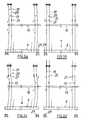
- FIGS. 5a to 5d schematically show how the four possible transitions between the two positions of the board 6 are made possible in the second embodiment.
- the control needle 16 assumes two positions: a first position in which the strips 19, 20 are bent laterally (FIGS. 5a and 5c), and a second position in which the strips 19 or 20 remain straight, i.e. are not bent ( Figures 5b and 5d).
- the knives 15 cannot reach behind the hook-shaped lugs 21, and the board 6 remains on the supports 29 below (FIG.
- Knives 15 which already hook into the lugs 21, continue to carry the strips 19 or 20 or the board 6, so that it can lower, for example (FIG. 5c). If the strips remain straight, certain knives 15, the board 6 z. B. take upwards ( Figure 5b), or other knives 15 can take over the board 6, so that it stops at the top ( Figure 5d).
Landscapes
- Engineering & Computer Science (AREA)
- Textile Engineering (AREA)
- Looms (AREA)
- Knitting Machines (AREA)
- Load-Engaging Elements For Cranes (AREA)
Description
Jacquardmaschinen werden zum Weben von Figuren in Polgeweben angewendet. Beim Weben von Doppel-polgeweben gibt es zwei Grundgewebe: das Obergewebe und das Untergewebe, die mit ihren Oberseiten einander zugekehrt sind, und die während des Webens durch die Florkettfäden verbunden werden. Die Florkettfäden können beim Weben drei Positionen einnehmen, nämlich oberhalb des Obergewebes, in der Mitte zwischen den beiden Grundgeweben oder unter dem Untergewebe. Dies ist diejenige Jacquardmaschine, die jeden Florkettfaden vor jedem Schuss in eine jener Positionen hineinbringt.Jacquard machines are used to weave figures in pile fabrics. When weaving double-pile fabrics, there are two basic fabrics: the upper fabric and the lower fabric, which face each other with their tops and which are connected by the pile warp threads during weaving. The pile warp threads can assume three positions during weaving, namely above the upper fabric, in the middle between the two basic fabrics or below the lower fabric. This is the jacquard machine that brings each pile warp thread into one of those positions before each shot.
In der belgischen Patentschrift Nr. 894.283 ist eine Rollenzugeinrichtung einer Offenfach-Jacquardmaschine beschrieben, bei der das eine Ende der Strupfe an einer Platine und das andere Ende an einer bewegbaren Aufhänge-Einrichtung bzw. zugleich die Harnischschnüre mit einem Aussenende am Harnisch und mit dem anderen Ende an einer festen Aufhänge-Einrichtung festgemacht sind.Belgian patent specification No. 894.283 describes a roller pulling device of an open-pocket jacquard machine, in which one end of the stockings on a circuit board and the other end on a movable suspension device, or at the same time the harness cords with an outer end on the harness and with the other Are attached to a fixed suspension device.
Die bewegbare Aufhänge-Einrichtung besteht dabei aus auf- und abbewegbaren Brettern an denen die Enden einer oder mehrerer Strupfe festgemacht werden, so dass jene Enden blockweise, einem bestimmten Rapport folgend, gesteuert werden können.The movable suspension device consists of up and down movable boards on which the ends of one or more strings are fastened, so that those ends can be controlled in blocks, following a specific repeat.
Eine derartige Rollenzugeinrichtung übernimmt die Vorteile der Offenfach-Jacquardmaschine mit Rollenzug-Elementen, umgeht den Nachteil, dass je angesteuertem Punkt zwei Platinen zu gebrauchen sind, und lässt maximale Musterungsmöglichkeiten bei geringstem Platzbedarf zu.Such a roller pulling device takes over the advantages of the open-pocket jacquard machine with roller pulling elements, avoids the disadvantage that two boards have to be used for each point controlled, and permits maximum patterning options with the smallest space requirement.
Während beim Gegenstand des belgischen Patentes die Bretter von einer Kurve über einen Hebegetriebe angetrieben werden, also ein gesonderter Antrieb notwendig ist, ist es das Ziel der vorliegenden Erfindung, den zusätzlichen Antrieb zu vermeiden.While the boards of the Belgian patent are driven by a curve via a lifting gear, a separate drive is required , the aim of the present invention is to avoid the additional drive.
Die Jacquardmaschine gemäss der Erfindung, bei der das eine Aussenende der Strupfen an einer Platine und das andere Aussenende an einer bewegbaren AufhängeEinrichtung und die Harnischschnüre mit einem Aussenende am Harnisch und dem anderen Aussenende an einer festen Aufhänge-Einrichtung festgemacht sind, ist dadurch gekennzeichnet, dass die bewegbaren Aufhänge-Einrichtungen von dem Messerrost der Jacquardmaschine angetrieben werden und daß die bewegbaren Aufhänge-Einrichtungen jeweils an einer Anzahl Platinen aufgehängt sind, die an dem Messerrost der Jacquardmaschine einhaken können, und die dazu mit eingenen Steuernadeln versehen sind.The jacquard machine according to the invention, in which the one outer end of the hosiery is attached to a board and the other outer end to a movable suspension device and the harness cords with an outer end to the harness and the other outer end to a fixed suspension device, is characterized in that the movable suspension devices are driven by the knife grate of the jacquard machine and that the movable suspension devices are each suspended on a number of boards which can hook onto the knife grate of the jacquard machine and which are provided with their own control needles for this purpose.
Bei einer bevorzugten Ausführungsform der Jacquardmaschine gemäss der Erfindung besteht jede Platine, die einen Teil der bewegbaren Aufhänge-Einrichtung trägt, aus zwei nahe beieinander angeordneten Flachstahl- oder Kunststoffleisten, die in passender Höhe mit einer hakenförmigen Nase versehen sind, die auf den Messerreihen einhaken kann.In a preferred embodiment of the jacquard machine according to the invention, each plate, which carries part of the movable suspension device, consists of two flat steel or plastic strips arranged close to one another, which are provided at a suitable height with a hook-shaped nose which can hook onto the rows of knives .
Bezüglich der in der belgischen Patentschrift Nr. 894.283 beschriebenen Jacquardmaschine hat die Jacquardmaschine gemäss der Erfindung den Vorteil, dass der zusätzliche Antrieb für jedes bewegbare Brett vermieden wird, dass die Synchronisierung zwischen der Bewegung der Platinen und der des Brettes leichter zu realisieren ist, und dass die Bewegung des Brettes leichter und umfassender zu programmieren ist.With respect to the jacquard machine described in Belgian Patent No. 894,283, the jacquard machine according to the invention has the advantage that the additional drive for each movable board is avoided, that the synchronization between the movement of the boards and that of the board is easier to implement, and that the movement of the board is easier and more comprehensive to program.
Weitere Besonderheiten und Vorteile ergeben sich aus der nachfolgenden Beschreibung einer als Beispiel herangeholten, bevorzugten Ausführungsform der Jacquardmaschine gemäss der Erfindung. In der Beschreibung wird auf die beigefügten Figuren bezuggenommen:
Figur 1 ist eine schematische Ansicht der Arbeitsweise einer Jacquardmaschine mit blockweise gesteuerten Rollenzugeinrichtungen bei einer dreischüssigen V-Bindung gemäss dem belgischen Patent Nr. 894.283.Figur 2 ist eine schematische Ansicht einer ersten Ausführungsform eines Abschnittes der Jacquardmaschine gemäss der Erfindung.Figur 3 ist eine perspektivische Ansicht von einem Abschnitt der Steuernadel und von einem Flachstahl-oder Kunststoffleistenpaar, das eine Platine für eine zweite Ausführungsform der Jacquardmaschine gemäss der Erfindung bildet.- Figur 4 ist eine schematische Ansicht der zweiten Ausführungsform des Abschnittes der Jacquardmaschine gemäss der Erfindung.
- Die Figuren 5a bis 5d sind schematische Ansichten der vier möglichen Übergänge zwischen zwei Positionen des Brettes der Jacquardmaschine gemäss der Erfindung.
- FIG. 1 is a schematic view of the operation of a jacquard machine with block-controlled roller pulling devices in a three-shot V-binding according to Belgian patent no. 894.283.
- Figure 2 is a schematic view of a first embodiment of a portion of the jacquard machine according to the invention.
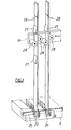
- FIG. 3 is a perspective view of a section of the control needle and of a pair of flat steel or plastic strips, which forms a circuit board for a second embodiment of the jacquard machine according to the invention.
- Figure 4 is a schematic view of the second embodiment of the section of the jacquard machine according to the invention.
- Figures 5a to 5d are schematic views of the four possible transitions between two positions of the board of the jacquard machine according to the invention.
Um die Arbeitsweise der Jacquardmaschine gemäss der Erfindung gut zu verstehen, wird das Prinzip einer Jacquardmaschine mit blockweise gesteuerten Rollenzugeinrichtungen anhand der Figur 1 kurz erläutert. Bei einer solchen Jacquardmaschine trägt eine Platine 1 das eine Ende 2 einer Rollenstrupfe 3, die um eine Rolle 4 läuft. Das andere Ende 5 jener Rollenstrupfe 3 ist beispielsweise an einer bewegbaren Aufhänge-Einrichtung, vorzugsweise einem Brett 6 oder 7 befestigt. Jedes Brett 6 oder 7 trägt das Ende mehrerer Rollenstrupfe 3. Der Rolle 4 ist eine Rolle 8 zugeordnet, um die eine Harnischschnur 9 herumläuft, deren eines Ende 10 dann mit einer festen Aufhänge-Einrichtung 11 und deren anderes Ende 12 mit dem Harnisch (nicht gezeigt) verbunden ist. Um die Kettfäden I, II, III, IV wahlweise in eine ihrer drei möglichen Positionen zu bewegen, genügt es, die Platinen 1 in eine von zwei mit "unten" (0) oder "oben" (B) bezeichnete Positionen zu bewegen in Kombination mit den Brettern 6 oder 7, die in ein von zwei mit "unten" (0) oder "oben" (B) bezeichnete Positionen zu bewegen sind.In order to understand the operation of the jacquard machine according to the invention well, the principle of a jacquard machine with block-controlled roller pulling devices will be briefly explained with reference to FIG. 1. In such a jacquard machine, a
Aus der Figur 1 ergibt sich somit, dass die Bretter 6 oder 7 in der Lage sein müssen, vier mögliche Bewegungsübergänge auszuführen: oben _ oben, oben _ unten, unten _ unten, unten _ oben. In der Figur 1 ist ferner der Platinenboden 13 der Jacquardmaschine angedeutet.It therefore follows from FIG. 1 that the
Bei der Jacquardmaschine gemäss der Erfindung, die in den Figuren 2 und 4 gezeigt ist, werden jene Bewegungsübergänge der bewegbaren Aufhänge-Einrichtungen, in diesem Fall der Bretter 6 oder 7 durch die Jacquardmaschine selbst angetrieben.In the jacquard machine according to the invention, which is shown in FIGS. 2 and 4, those movement transitions of the movable suspension devices, in this case the
Bei einer ersten Ausführungsform der Jacquardmaschine gemäss der Erfindung, die in der Figur 2 dargestellt ist, wird ein Brett 6 mit Hilfe einer Anzahl Platinen 14 der klassischen Jacquardmaschine aufgehängt. Jene Platinen 14 sind auf eine gewisse Zahl Reihen, in der Tiefenrichtung des Brettes 6 und parallel zu den Seitenrändern des Brettes 6 gelegen, und können von den Messern 15 der Messerroste mitgenommen werden. Dazu werden alle Platinen 14 einer Reihe von einem Brett jeweils durch eine horizontale Verschiebung von sich gemeinsam bewegenden Steuernadeln 16 innerhalb oder ausserhalb des Bereiches der Messer 15 angeordnet. Genauso wie die Platinen 1 der Rollenstrupfe 3 der Figur 1 können auch die Platinen 14 infolge ihres Zusammenwirkens mit den Messern 15 der Messerroste die vier Übergänge zwischen den beiden erforderlichen Positionen oben und unten durchlaufen.In a first embodiment of the jacquard machine according to the invention, which is shown in FIG. 2, a
In bestimmten Fällen haben die Platinen der klassischen Jacquardmaschine eine zu geringe Stärke. Im Hinblick darauf, dass der Angriffspunkt 17 eines Teiles des Gewichtes und der Belastung des Brettes 6 nicht genau unterhalb der Nasen 18 der Platinen 14 liegt, kann sich eine derartige Platine bei einer hohen Belastung unter dem Einfluss des in ihr auftretenden Biegemomentes verbiegen, so dass die Nasen 18 nicht mehr in der Bahn der Messer 15 bleiben und eine einwandfreie Arbeitsweise der Jacquardmaschine nicht mehr gewährleistet ist.In certain cases, the boards of the classic jacquard machine are too thin. In view of the fact that the point of attack 17 of part of the weight and the load on the
Um diesem Problem abzuhelfen, wurde eine neue Platine entwickelt, die aus zwei Flachstahl- oder Kunststoffleisten 19 und 20 (Figur 3) besteht. Jede klassische Platine 14 der Figur 2 wird somit durch die beiden Leisten 19 und 20 ersetzt, die in passender Höhe mit hakenförmigen Nasen 21 versehen sind, die mit den Nasen 18 der klassischen Platinen 14 (Figur 2) übereinstimmen. Jene Leisten 19 und 20 sind dann derart in der Jacquardmaschine angeordnet, dass die Steuernadel 16 ihren kleinsten Leisten-Biegewiderstand zu überwinden hat, oder dass die kleinste Abmessung des Leisten-Querschnittes parallel zur Bewegung der Nadel 16 verläuft. Der Querschnitt der Leisten 19 und 20 ist somit derart gewählt, dass er zur Aufnahme der Brettbelastungen gross genug ist, und dass er in einer einzigen Richtung den gewünschten, geringen Biegewiderstand aufweist.To remedy this problem, a new circuit board was developed, which consists of two flat steel or
Jene Leiste 19 und 20 werden dann unten jeweils paarweise mit Scharnieren am Seitenrand entlang und in der Tieferichtung des Brettes 6 befestigt (Figur 4); Jene Scharnierverbindung kann aus einer kurzen Achse 22 bestehen, die am Brett 6 befestigt ist, und um die sich das ringförmige Aussenende der Leisten 19 und 20 dreht. Diese Leisten 19 und 20 laufen frei nach oben durch den Platinenboden 13 hindurch. Oberhalb sind sie in eine feste Geradführung 23 eingeschoben, die eine gewisse Verbiegung der Leisten 19 und 20 zulässt. Das obere Ende der Leisten 19 und 20 wird dazu beispielsweise drehbar oder mit einigem Spiel in einem kleinen Führungsblock eingefasst.Those
Die Scharnierverbindung unten kann auch mit Spiel ausgeführt sein. Eine bevorzugte Ausführungsform jener Verbindung ist in Figur 3 gezeigt. An den Stellen, an denen die Leisten 19 oder 20 in das Brett 6 eingreifen, ist stets ein Nut 24 vorgesehen. In der Tieferichtung des Brettes 6 und durch die Nut 24 hindurch ein oder zwei Öffnungen 25 ausgebildet, durch die ein langer Stab 26 hindurchgeschoben wird. Die unteren Aussenenden der Leisten 19 und 20 sind ebenfalls mit einer oder zwei Öffnungen 27 versehen, deren Querschnitt jedoch grösser als der des Stabes 26 ist. Die Leisten 19 und 20 können auf diese Weise leicht mit dem Brett 6 verbunden oder vom Brett 6 getrennt werden. Es genügt, den Stab 26 hinein oder hinaus und dabei durch die Öffnungen 27 zu schieben. Infolge des Unterschiedes in den Abmessungen ist ein gewisses Spiel an dieser Verbindung vorhanden. Dieses ist notwendig, weil der Brett 6 während seiner Aufwärtsbewegung noch einer leichten Schrägstellungsbewegung, der sog. Schrägfachbewegung, unterliegt.The hinge connection below can also be designed with play. A preferred embodiment that connection is shown in FIG. A
Auch die Steuernadel 16 (Figur 3) hat bei dieser zweiten Ausführungsform eine entsprechend angepasste Gestalt. In der Höhe der Leiste 19 oder 20 ist die Steuernadel 16 mit zwei Röllchen 28 versehen, die zwischen den hakenförmigen Nasen 21 an den Leisten 19 oder 20 angreifen. Alle Steuernadeln 16 desselben Bretts 6 unterliegen derselben Bewegung, die durch einen Kurvensteuerung, durch einen oder mehrere Druckzylinder oder durch einem aus den Jacquard-Karten gesteurerten Vorwahlapparat erzeugt wird.The control needle 16 (FIG. 3) also has a correspondingly adapted shape in this second embodiment. At the level of the
Diese Bewegung ist einfach mit der Bewegung der gewöhnlichen Platinen zu synchronisieren, die die Rollenstrupfe hochheben; sie ist leicht mit den Jacquardkarten zu programmieren.This movement is easy to synchronize with the movement of the ordinary boards that lift the roller brackets; it is easy to program with the jacquard cards.
Bei der ersten Ausführungsform gemäss Figur 2 hängt das Brett 6 in seiner untersten Position an den Platinen 14, die sich auf der Oberseite des Platinenbodens 13 abstützen, geradeso wie es bei den Platinen 1, an denen die Rollenstrupfe 3 (Figur 1) hängen, der Fall ist. Im Hinblick darauf, dass die Leisten 19 und 20 frei durch den Platinenboden 13 verschoben werden können, sind bei der zweiten Ausführungsform Stützen 29 für das Brett 6 (Figur 4) vorgeschen, auf denen das Brett ruht, wenn es sich in seiner untersten Position befindet.In the first embodiment according to Figure 2, the
Die Figuren 5a bis 5d geben schematisch wieder, wie bei der zweiten Ausfürhrungsform die vier möglichen Übergänge zwischen den beiden Positionen des Brettes 6 ermöglicht werden. Die Steuernadel 16 nimmt dabei zwei Stellungen ein: eine erste Stellung, in der die Leisten 19, 20 seitlich verbogen werden (Figuren 5a und 5c), und eine zweite Stellung, in der die Leisten 19 oder 20 gerade bleiben, also nicht verbogen sind (Figuren 5b und 5d). Im Falle verbogener Leisten 19 und 20 können die Messer 15 nicht hinter die hakenförmigen Nasen 21 greifen, und das Brett 6 bleibt unten auf den Stützen 29 (Figur 5a), oder die freien Messer 15 können nicht hinter die hakenförmigen Nasen 21 eingreifen, und jene Messer 15, die bereits in die Nasen 21 einhaken, tragen weiterhin die Leisten 19 oder 20 oder das Brett 6, sodass es beispielsweise absenken kann (Figur 5c). Falls die Leisten gerade bleiben, können bestimmte Messer 15 das Brett 6 z. B. nach oben hin mitnehmen (Figur 5b), oder es können andere Messer 15 das Brett 6 übernehmen, sodass es oben stehenbleibt (Figur 5d).FIGS. 5a to 5d schematically show how the four possible transitions between the two positions of the
Claims (14)
Applications Claiming Priority (2)
| Application Number | Priority Date | Filing Date | Title |
|---|---|---|---|
| BE8700128A BE1000304A5 (en) | 1987-02-13 | 1987-02-13 | OPEN GAAP jacquard WHOSE HOIST DEVICE BY MOVING UP AND DOWN SHELVES IN CAPITAL IS SENT. |
| BE8700128 | 1987-02-13 |
Publications (2)
| Publication Number | Publication Date |
|---|---|
| EP0280132A1 EP0280132A1 (en) | 1988-08-31 |
| EP0280132B1 true EP0280132B1 (en) | 1991-06-05 |
Family
ID=3882515
Family Applications (1)
| Application Number | Title | Priority Date | Filing Date |
|---|---|---|---|
| EP88102105A Expired - Lifetime EP0280132B1 (en) | 1987-02-13 | 1988-02-12 | Open-shed jacquard machine with a pulley train block-controlled with the aid of boards moving upwards and downwards |
Country Status (6)
| Country | Link |
|---|---|
| US (1) | US4858654A (en) |
| EP (1) | EP0280132B1 (en) |
| BE (1) | BE1000304A5 (en) |
| DD (1) | DD279908A5 (en) |
| DE (1) | DE3863088D1 (en) |
| ES (1) | ES2023445B3 (en) |
Families Citing this family (17)
| Publication number | Priority date | Publication date | Assignee | Title |
|---|---|---|---|---|
| DE3817416C1 (en) * | 1988-05-21 | 1989-07-06 | Fa. Oskar Schleicher, 4050 Moenchengladbach, De | |
| FR2647473B1 (en) * | 1989-05-24 | 1991-07-26 | Staubli Verdol | IMPROVEMENTS ON THREE-POSITION ARMOR MECHANICS |
| DD284921A5 (en) * | 1989-06-12 | 1990-11-28 | Veb Kombinat Textima,Dd | PLATINUM CONTROL OF THE OFFENBACH-JACQUARD MACHINE OF A PLUESCHWEBMASCHINE, IN PARTICULAR OF A DOUBLE RUG WEAVING MACHINE |
| DD284920B3 (en) * | 1989-06-12 | 1993-01-28 | Chemnitzer Webmasch Gmbh | JACQUARD DEVICE FOR DOUBLE TISSUE WEAVING MACHINES WITH DOUBLE OPEN COMPARTMENT |
| TR25799A (en) * | 1991-01-18 | 1993-09-01 | Oskar Schleicher Union Carbide | A PROCESS FOR INCREASING THE NISPI VISCOSITY OF POLYAMIDES WITH NUCLE OF VYPELY COPOLIMER DEPOSITION WITH BOXED WOVEN IM IMPROPERATION |
| DE4101778C1 (en) * | 1991-01-18 | 1992-04-02 | Fa. Oskar Schleicher, 4050 Moenchengladbach, De | |
| FR2676073A1 (en) * | 1991-05-03 | 1992-11-06 | Wittendal Sa Ets Richard | METHOD FOR SELECTING HOOKS OF A JACQUARD MECHANICAL AND HOOKS FOR SUCH A MECHANICAL. |
| BE1008209A4 (en) * | 1993-04-23 | 1996-02-13 | Wiele Michel Van De Nv | Jacquard. |
| EP0668381B1 (en) * | 1994-01-26 | 1997-06-18 | Danilo Jaksic | Jacquard machine |
| BE1008975A5 (en) * | 1994-12-20 | 1996-10-01 | Wiele Michel Van De Nv | Jacquard WITH rigging. |
| BE1008974A5 (en) * | 1994-12-20 | 1996-10-01 | Wiele Michel Van De Nv | HOISTING EQUIPMENT FOR A JACQUARD MACHINE. |
| US5647403A (en) * | 1995-04-04 | 1997-07-15 | Milliken Research Corporation | Jacquard loom latch control mechanism |
| FR2742170B1 (en) * | 1995-12-12 | 1998-01-23 | Staubli Verdol | IMPROVEMENTS IN MECHANICS OF DOUBLE-RISE ARMOR |
| BE1019154A5 (en) * | 2010-01-15 | 2012-04-03 | Wiele Michel Van De Nv | SELECTION DEVICE FOR THE GAAPING DEVICE OF A WEAVING MACHINE. |
| BE1021951B1 (en) * | 2014-07-18 | 2016-01-28 | Michel Van De Wiele Nv | GAAP FORMAT FOR A WEAVING MACHINE |
| EP3112509A1 (en) * | 2015-07-02 | 2017-01-04 | NV Michel van de Wiele | Connecting member for connecting elements of a shed forming mechanism for a weaving machine with each other |
| EP3165643B1 (en) * | 2015-11-04 | 2018-04-18 | NV Michel van de Wiele | Jacquard machine, face-to-face weaving machine comprising at least one jacquard machine, and method of setting up a jacquard machine |
Family Cites Families (10)
| Publication number | Priority date | Publication date | Assignee | Title |
|---|---|---|---|---|
| GB141592A (en) * | 1919-08-16 | 1920-04-22 | William Lavery | Improvements relating to jacquard machines |
| FR1157431A (en) * | 1956-08-20 | 1958-05-29 | Lehembre & Cie A | Three-position jacquard machine for weaving three- and four-pick rugs per tassel |
| FR1050774A (en) * | 1956-08-20 | 1954-01-11 | Lehembre & Cie A | Universal multi-position mechanics for looms |
| FR1212294A (en) * | 1958-10-03 | 1960-03-23 | Lehembre & Cie A | Three-position jacquard mechanism for carpet weaving |
| CH507394A (en) * | 1970-02-19 | 1971-05-15 | App Fabrik Ag Huttwil | Open shed double stroke jacquard machine |
| DE2530799C3 (en) * | 1975-07-10 | 1982-04-15 | Fa. Oskar Schleicher, 4050 Mönchengladbach | Double-stroke open-shed jacquard machine |
| FR2496715A1 (en) * | 1980-12-23 | 1982-06-25 | Verdol Sa | ARMOR MECHANISM OF THE GENUS VERDOL OR JACQUARD PROVIDED WITH MEANS OF ENSURING EASY CROSSING OF CLAWS |
| DE3113434A1 (en) * | 1981-04-03 | 1982-10-21 | Fa. Oskar Schleicher, 4050 Mönchengladbach | DOUBLE-LIFT OPEN-POCKET JACKET MACHINE |
| BE894283A (en) * | 1982-09-02 | 1983-01-03 | P V B A Van De Wiele Internat | Open-shed jacquard pile fabric weaving loom - has each harness cord operated by only one figuring hook and separately actuated element |
| FR2674385A1 (en) * | 1991-03-22 | 1992-09-25 | Alsthom Gec | GALVANIC ISOLATION DEVICE FOR CONTINUOUS ELECTRIC SIGNALS OR LIKELY TO CONTAIN A CONTINUOUS COMPONENT. |
-
1987
- 1987-02-13 BE BE8700128A patent/BE1000304A5/en not_active IP Right Cessation
-
1988
- 1988-02-08 US US07/153,098 patent/US4858654A/en not_active Expired - Fee Related
- 1988-02-11 DD DD88312842A patent/DD279908A5/en unknown
- 1988-02-12 EP EP88102105A patent/EP0280132B1/en not_active Expired - Lifetime
- 1988-02-12 ES ES88102105T patent/ES2023445B3/en not_active Expired - Lifetime
- 1988-02-12 DE DE8888102105T patent/DE3863088D1/en not_active Expired - Lifetime
Also Published As
| Publication number | Publication date |
|---|---|
| ES2023445B3 (en) | 1992-01-16 |
| EP0280132A1 (en) | 1988-08-31 |
| DD279908A5 (en) | 1990-06-20 |
| DE3863088D1 (en) | 1991-07-11 |
| BE1000304A5 (en) | 1988-10-11 |
| US4858654A (en) | 1989-08-22 |
Similar Documents
| Publication | Publication Date | Title |
|---|---|---|
| EP0280132B1 (en) | Open-shed jacquard machine with a pulley train block-controlled with the aid of boards moving upwards and downwards | |
| DE60319296T2 (en) | Weaving machine and method of weaving pole loop fabrics | |
| DE69707995T3 (en) | Method and device for selecting the movable hooks of a shed forming device and jacquard weaving machine | |
| DE69005028T2 (en) | Improvements to three position jacquard devices. | |
| DE69220043T2 (en) | MULTIAXIAL WEAVING | |
| EP0459582B1 (en) | Block and pulley tackle suspension for Jacquard machine and Jacquard machine with such block and tackle pulley suspension | |
| EP0627511B1 (en) | Jacquard machine | |
| EP0570947B1 (en) | Tackle mechanism for a jacquard machine | |
| DE19547765B4 (en) | Jacquard machine with pulley device | |
| DE2409421C2 (en) | Device for the mechanical actuation of thread guide members | |
| DE19924214C2 (en) | Working method and weaving machine for weaving a pile fabric | |
| DE2227490A1 (en) | Device for achieving control of the movements of the thread guide element in a textile machine | |
| EP2236655B1 (en) | Jacquard loom and Jacquard machine | |
| EP0106974B1 (en) | Pulley train for a jacquard loom | |
| EP1255885B1 (en) | Method for deflecting a warp thread sheet during weaving and a weaving machine | |
| EP1101850A1 (en) | Device to form a leno weave | |
| DE69803007T2 (en) | Four-position open-shed jacquard | |
| DE1535249B1 (en) | TECHNICAL DEVICE FOR WEAVING MACHINES | |
| DE4440440A1 (en) | Jacquard rib knitting machine for knitting eyelet and push-up designs | |
| DE2457122A1 (en) | WEAVING PROCESS FOR THE PRODUCTION OF PILOT FABRICS | |
| DD284920B3 (en) | JACQUARD DEVICE FOR DOUBLE TISSUE WEAVING MACHINES WITH DOUBLE OPEN COMPARTMENT | |
| EP0502528A1 (en) | Force transducer mechanism for lifting or lowering at least one warp thread in a jacquard machine, particularly an open-shed jacquard machine | |
| DE135118C (en) | ||
| DE2625178C3 (en) | Device for controlling the patterning of a product made on a lace machine | |
| DE61729C (en) | Jacquard machine with device for saving Kaneners |
Legal Events
| Date | Code | Title | Description |
|---|---|---|---|
| PUAI | Public reference made under article 153(3) epc to a published international application that has entered the european phase |
Free format text: ORIGINAL CODE: 0009012 |
|
| AK | Designated contracting states |
Kind code of ref document: A1 Designated state(s): CH DE ES FR GB IT LI NL |
|
| 17P | Request for examination filed |
Effective date: 19881122 |
|
| 17Q | First examination report despatched |
Effective date: 19900426 |
|
| GRAA | (expected) grant |
Free format text: ORIGINAL CODE: 0009210 |
|
| AK | Designated contracting states |
Kind code of ref document: B1 Designated state(s): CH DE ES FR GB IT LI NL |
|
| REF | Corresponds to: |
Ref document number: 3863088 Country of ref document: DE Date of ref document: 19910711 |
|
| ET | Fr: translation filed | ||
| GBT | Gb: translation of ep patent filed (gb section 77(6)(a)/1977) | ||
| ITF | It: translation for a ep patent filed | ||
| REG | Reference to a national code |
Ref country code: ES Ref legal event code: FG2A Ref document number: 2023445 Country of ref document: ES Kind code of ref document: B3 |
|
| PLBE | No opposition filed within time limit |
Free format text: ORIGINAL CODE: 0009261 |
|
| STAA | Information on the status of an ep patent application or granted ep patent |
Free format text: STATUS: NO OPPOSITION FILED WITHIN TIME LIMIT |
|
| 26N | No opposition filed | ||
| PGFP | Annual fee paid to national office [announced via postgrant information from national office to epo] |
Ref country code: GB Payment date: 19930105 Year of fee payment: 6 |
|
| PGFP | Annual fee paid to national office [announced via postgrant information from national office to epo] |
Ref country code: NL Payment date: 19930228 Year of fee payment: 6 |
|
| PGFP | Annual fee paid to national office [announced via postgrant information from national office to epo] |
Ref country code: CH Payment date: 19930504 Year of fee payment: 6 |
|
| PG25 | Lapsed in a contracting state [announced via postgrant information from national office to epo] |
Ref country code: GB Effective date: 19940212 |
|
| PG25 | Lapsed in a contracting state [announced via postgrant information from national office to epo] |
Ref country code: LI Effective date: 19940228 Ref country code: CH Effective date: 19940228 |
|
| PG25 | Lapsed in a contracting state [announced via postgrant information from national office to epo] |
Ref country code: NL Effective date: 19940901 |
|
| GBPC | Gb: european patent ceased through non-payment of renewal fee |
Effective date: 19940212 |
|
| NLV4 | Nl: lapsed or anulled due to non-payment of the annual fee | ||
| REG | Reference to a national code |
Ref country code: CH Ref legal event code: PL |
|
| PGFP | Annual fee paid to national office [announced via postgrant information from national office to epo] |
Ref country code: ES Payment date: 19960223 Year of fee payment: 9 |
|
| PG25 | Lapsed in a contracting state [announced via postgrant information from national office to epo] |
Ref country code: ES Free format text: LAPSE BECAUSE OF NON-PAYMENT OF DUE FEES Effective date: 19970213 |
|
| REG | Reference to a national code |
Ref country code: ES Ref legal event code: FD2A Effective date: 19990201 |
|
| PGFP | Annual fee paid to national office [announced via postgrant information from national office to epo] |
Ref country code: IT Payment date: 20060228 Year of fee payment: 19 |
|
| PGFP | Annual fee paid to national office [announced via postgrant information from national office to epo] |
Ref country code: DE Payment date: 20070216 Year of fee payment: 20 |
|
| PGFP | Annual fee paid to national office [announced via postgrant information from national office to epo] |
Ref country code: FR Payment date: 20070212 Year of fee payment: 20 |
|
| PG25 | Lapsed in a contracting state [announced via postgrant information from national office to epo] |
Ref country code: IT Free format text: LAPSE BECAUSE OF NON-PAYMENT OF DUE FEES Effective date: 20070212 |