EP0280127B1 - Pneumodensitometric vibrating separator for sorting of heterogeneous bulk products - Google Patents
Pneumodensitometric vibrating separator for sorting of heterogeneous bulk products Download PDFInfo
- Publication number
- EP0280127B1 EP0280127B1 EP88102053A EP88102053A EP0280127B1 EP 0280127 B1 EP0280127 B1 EP 0280127B1 EP 88102053 A EP88102053 A EP 88102053A EP 88102053 A EP88102053 A EP 88102053A EP 0280127 B1 EP0280127 B1 EP 0280127B1
- Authority
- EP
- European Patent Office
- Prior art keywords
- air
- separator
- side frames
- vibrating
- dust
- Prior art date
- Legal status (The legal status is an assumption and is not a legal conclusion. Google has not performed a legal analysis and makes no representation as to the accuracy of the status listed.)
- Expired - Lifetime
Links
Images

Classifications
-
- B—PERFORMING OPERATIONS; TRANSPORTING
- B07—SEPARATING SOLIDS FROM SOLIDS; SORTING
- B07B—SEPARATING SOLIDS FROM SOLIDS BY SIEVING, SCREENING, SIFTING OR BY USING GAS CURRENTS; SEPARATING BY OTHER DRY METHODS APPLICABLE TO BULK MATERIAL, e.g. LOOSE ARTICLES FIT TO BE HANDLED LIKE BULK MATERIAL
- B07B9/00—Combinations of apparatus for screening or sifting or for separating solids from solids using gas currents; General arrangement of plant, e.g. flow sheets
- B07B9/02—Combinations of similar or different apparatus for separating solids from solids using gas currents
-
- B—PERFORMING OPERATIONS; TRANSPORTING
- B03—SEPARATION OF SOLID MATERIALS USING LIQUIDS OR USING PNEUMATIC TABLES OR JIGS; MAGNETIC OR ELECTROSTATIC SEPARATION OF SOLID MATERIALS FROM SOLID MATERIALS OR FLUIDS; SEPARATION BY HIGH-VOLTAGE ELECTRIC FIELDS
- B03B—SEPARATING SOLID MATERIALS USING LIQUIDS OR USING PNEUMATIC TABLES OR JIGS
- B03B4/00—Separating by pneumatic tables or by pneumatic jigs
- B03B4/02—Separating by pneumatic tables or by pneumatic jigs using swinging or shaking tables
-
- B—PERFORMING OPERATIONS; TRANSPORTING
- B07—SEPARATING SOLIDS FROM SOLIDS; SORTING
- B07B—SEPARATING SOLIDS FROM SOLIDS BY SIEVING, SCREENING, SIFTING OR BY USING GAS CURRENTS; SEPARATING BY OTHER DRY METHODS APPLICABLE TO BULK MATERIAL, e.g. LOOSE ARTICLES FIT TO BE HANDLED LIKE BULK MATERIAL
- B07B13/00—Grading or sorting solid materials by dry methods, not otherwise provided for; Sorting articles otherwise than by indirectly controlled devices
- B07B13/14—Details or accessories
- B07B13/16—Feed or discharge arrangements
-
- B—PERFORMING OPERATIONS; TRANSPORTING
- B07—SEPARATING SOLIDS FROM SOLIDS; SORTING
- B07B—SEPARATING SOLIDS FROM SOLIDS BY SIEVING, SCREENING, SIFTING OR BY USING GAS CURRENTS; SEPARATING BY OTHER DRY METHODS APPLICABLE TO BULK MATERIAL, e.g. LOOSE ARTICLES FIT TO BE HANDLED LIKE BULK MATERIAL
- B07B7/00—Selective separation of solid materials carried by, or dispersed in, gas currents
- B07B7/06—Selective separation of solid materials carried by, or dispersed in, gas currents by impingement against sieves
Definitions
- This invention covers a pneumodensitometric vibrating separator table for separation of heterogeneous bulk products, in particular compost, i.e. to separate fertilizers obtained through aerobic biotransformation of putrescible organic solid domestic wastefractions, from other foreign matter not yet kept back during previous sorting.
- Pneumodensitometric vibrating separators are known in which the vibrating or oscillating table, provided with a permeable bottom or bed through which air flows so as to form an air stream fluidizing the heterogenous matter to be sorted out which is located above this air stream.
- this vibrating or oscillating motion is unidirectional according to pulses having a 20°-30° inclination with respect to the longitudinal sorting plane, this inclination being based upon the material to be treated; furthermore, the inclination angle of the separator table has the same direction as the vibration or oscillation pulse angle.
- the heterogeneous material on the table is thus separated by gravity due to the upwards penetrating air stream; the particulate matter having a higher specific gravity will tend to move downwards in touch with the table, while those with a lower specific gravity will tend to float.
- a vibrating separator as described is known by EP-A-0081072 in which it is substantially foreseen an inclinated, oscillating and permeable table, on which the heterogeneous material is separated by gravity and by air stream fluidizing.
- This document aims to better the separation adopting on the table transversal plates, useful to detain the heterogeneous material over the heavier components.
- a first drawback is caused by the fact that existing pneumodensitometric tables have a rather uneven vibrating or oscillating motion because of their poorly secured, scantily stretched, flat perforated bottom. As a result, the perforated plate will be subject to deformation, particularly during use, losing its stiffness and uniform movement, negatively affecting the sorting operation.
- a second drawback is due to the vibration and oscillation characteristics as currently used, which do not allow for adequate separation of very dense, tine particle layers such as for instance glass splinters, sand, porcelane or earthenware chips, small pieces of rigid plastic material etc.
- Another disadvantage lies in the fact that it is impossible with existing pneomodensitometric separators to change the direction of vibration or oscillation so that the operating conditions cannot be adjusted to the nature of the material to be treated.
- This patent has the aim to eliminate all above listed drawbacks of the known pneumodensitometric separators and to optimize sorting of heterogeneous bulk material.
- the fluidizing bed is centered and is resting on intermediate supports.
- the table is well secured and the vibratory motion over its whole surface is perfectly uniform.
- the vibratory or oscillating motion is directly and evenly transmitted to the sorting plane by means of stiffening side frames.
- a rather high vibration frequency with low amplitude has been chosen so as to boost separation of even small sized high density matter.
- the unidirectional vibratory motion is indeed involving 1000 to 3000 vibrations per minute with a 0.5-4 mm amplitude.
- unidirectional vibration is achieved by two vibrators or rotary propelling devices having controlled eccentric masses generating centrifugal forces by their identical and coplanar opposed rotation.
- the propelling assembly is rigidly connected to the side frames by means of sturdy links so that the two equal and opposed centrifugal forces, when combined, will provide the unidirectional reciprocating force necessary to impress the required motion.
- the system connecting the propelling devices to the side frames permits to vary the angle ⁇ resulting from the direction of the vibration force and the longitudinal plane of the separator and this system is also equipped with longitudinal conveyance facilities, so that the unidirectional vibratory forces are always passing through the center of gravity of the machine. It follows that the movement of the pneumodensitometric table can be adjusted based upon the quality of the material to be classified, in order to ensure its operation in optimum conditions.
- the drawback regarding the non uniform fluidizing action of the air stream is obviated by using a special sandwich panel as a permeable bed, the top of which is consisting of a closely perforated metal sheet (with closely-spaced holes having a diameter ranging between 0.5 and 0.6 mm), while the bottom is consisting of a high strength but low permeability filter fabric (nylon, polyester or polyamide, etc.).
- This sandwich panel will require a high air generator pressure (about 450-550 mm w.c.) to obtain an adequate air flow for fluidizing of the material, while the down flow will be virtually independent from the height of the top layer of the material.
- the Patent also eliminates the trouble caused by the fact that dust raised during fluidizing of the material and now collected by dust collectors has to be conveyed to cyclones and separate dust catching filters.
- the dust collecting system is an integrating part of the separator and is consisting of a filter mounted on the pneumodensitomteric table so as to create a plenum chamber from which coarser dust particles will fall back onto the table, whereas the finer particles are held back by the filter, there to felt up or agglomerate, until they are periodically returned to the fluidizing bed. This greatly simplifies dust catching equipment since a separate delivery system with all related handling problems is no longer necessary.
- the system also includes facilities for processing of special materials containing shreds of plastics or other fibrous fabrics which tend to flutter during fluidizing.
- the pneumodynamometric Table may perform an oscillating movement, i.e. a low frequency reciprocating movement (150-450 cycles/minute and high amplitude raging between 10 and 40 mm).
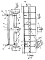
- the porous sandwich panel 1 is consisting of a closely perforated metal top sheet 2 and in a bottom filtering cloth 3 in moisture resisting synthetic fabric.
- This porous panel 1 is placed transversally, in a centered position, properly shimmed 4, resting on the frame of the separator so as to ensure a stable configuration.
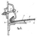
- the flanged panel edges are braced by stirrups 5 and turnbuckles 6 mounted on the side frames 7. This ensures a stable position of the perforated panel and its uniform vibratory motion.
- this sandwich panel has high strength and low permeability with respect to the fluidizing air flow.
- a closed chamber 8 is communicating at its lower end by means of an elastic coupling 9, with a high pressure fan 10 pressing the air through the porous panel.
- the tubular cross member 12, bearing the vibrators 11, is supported by U bolts 13 which can be moved along the sections 14, rigidly connected to the side frames 7.
- the vibrators 11 can rotate on the axis of the cross member 12 so that it will be possible to adjust the inclination angle ⁇ of the vibratory directions with respect to the longitudinal plane of the table 1 and the vibrators 11 can also be moved lengthwise forwards and backwards on the sections 14, so that the unidirectional vibrating force will pass through the center of gravity G of the vibrating part of the machine.
- This longitudinal traverse of the cross member 12 can be achieved, for example, by providing the section 14 with numerous holes in which the threaded ends of the U bolts 13 can be fitted.
- the pneumodensitometric table is supported by an appropriate mounting or frame 15 by means of flexible devices 16 such as cables, ropes, chains etc. secured to hooks 17 on the side frames 7.
- These flexible supporting means 16 are adjustable to ensure uniform distribution of the weight and position control of the table at its optimum longitudinal inclination angle ⁇ with respect to the horizontal plane.
- This angle ⁇ has the same direction as the angle ⁇ of the vibration forces with respect to the table plane.
- the unidirectional vibratory force has an ⁇ + ⁇ inclination with respect to the horizontal plane.
- An outlet 18 for the heavier particles B is provided in the upper section of the table while another outlet 19 in the lower table section discharges the finer and lighter particles C.
- the outlet 19 is fitted with an adjustable diaphragm 19 ⁇ determining the layer thickness of the material on the table.
- a feeder trough 10 delivers the product A on the pneumodensitometric table 1 for selection.
- the above explanations clearly illustrate the operation cycle.
- the product A to be sorted out is fed on the pneomodensitometric table 1 where it is fluidized by the air passing through the perforated plate. This will cause the broad or flat shaped light weight material having a low specific gravity, to be air entrained, without being effected by the vibratory impulses exerted on the table, while material having a high specific gravity will tend to settle on the vibrating surface and is thus moved forward under these pulse conditions.
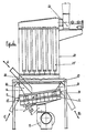
- a dust filter chamber 21 is located above the mounting 15 and is secured to the side frames of the pneumodensitometric table by means of a bellows 22.
- This filter chamber 21 is housing cloth tube filters 21 ⁇ . Dust is sucked through these cloth tubes by means of a suction fan 23.
- This configuration permits to combine the vibrating separator and dust filter in one single structure, thus offering additional functional advantages, since a spacious plenum chamber is available between the pneumodensitometric table and the dust filter, which is very useful for collection of coarse dust particles. Furthermore, any dust settling externally on the cloth tube filter 21 ⁇ will tend to agglomerate or felt and can be periodically discharged once more on the vibrating table. This will make a separate dust selection unnecessary, since the dust is mixed with the lighter products C.
- this patent presents a handy facility for separation and recovery of such air entrained waste.
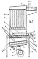
- This equipment is illustrated in Fig. n° 5 and n° 6 and is consisting of a loop shaped wire gauze or nylon belt 24 moving on two rolls or drums 25, 26, one of which 26 is motor-driven, acting as a tension roller and located at the back of the machine.
- This horizontal belt is intersecting the plenum chamber above the pneumodensitometric table and its lower leg moves towards the external roll 26.
- the lower outlet threshold 30 can be moved backward so that the air will prevailingly flow in direction of the arrow x with respect to y, to prevent the dust suction fan from generating excessive indraught in the machine which might detach the air entrained particles from the belt or prevent them from being externally discharged.
- the agglomerated dust when falling from the filter 21 will initially drop onto the upper belt section 24, to be conveyed to the roll 25 and from there dropped onto the pneumodensitometric table 1, to be subsequently discharged together with the lighter particles.
- the separator has therefore excellent operating features for sorting and classifying of heterogeneous material of any nature whatsoever; it has a built-in dust filter without separate dust recovery and also permits separation of air entrained matter which would be difficult to recover with existing separators.
Landscapes
- Combined Means For Separation Of Solids (AREA)
- Organic Low-Molecular-Weight Compounds And Preparation Thereof (AREA)
- Separation Of Solids By Using Liquids Or Pneumatic Power (AREA)
- Pharmaceuticals Containing Other Organic And Inorganic Compounds (AREA)
- Characterised By The Charging Evacuation (AREA)
- Seasonings (AREA)
- Fats And Perfumes (AREA)
- Physical Or Chemical Processes And Apparatus (AREA)
- Electrostatic Separation (AREA)
- Cleaning In General (AREA)
Abstract
Description
- This invention covers a pneumodensitometric vibrating separator table for separation of heterogeneous bulk products, in particular compost, i.e. to separate fertilizers obtained through aerobic biotransformation of putrescible organic solid domestic wastefractions, from other foreign matter not yet kept back during previous sorting.
- Pneumodensitometric vibrating separators are known in which the vibrating or oscillating table, provided with a permeable bottom or bed through which air flows so as to form an air stream fluidizing the heterogenous matter to be sorted out which is located above this air stream. Usually, this vibrating or oscillating motion is unidirectional according to pulses having a 20°-30° inclination with respect to the longitudinal sorting plane, this inclination being based upon the material to be treated; furthermore, the inclination angle of the separator table has the same direction as the vibration or oscillation pulse angle.
- The heterogeneous material on the table is thus separated by gravity due to the upwards penetrating air stream; the particulate matter having a higher specific gravity will tend to move downwards in touch with the table, while those with a lower specific gravity will tend to float.
- This means that the heavier components in touch with the table are exposed to the direct vibration or oscillation of the table and will move towards the top of the table where they are discharged, whereas lighter items will move downwards to be discharged there.
- A vibrating separator as described is known by EP-A-0081072 in which it is substantially foreseen an inclinated, oscillating and permeable table, on which the heterogeneous material is separated by gravity and by air stream fluidizing.
- This document aims to better the separation adopting on the table transversal plates, useful to detain the heterogeneous material over the heavier components.
- Besides there are known as technological background EP-A-0247423, DE-A-3606238, EP-A-0162014 and EP-A-0159050.
- These known pneumodensitometric tables for separation of heterogeneous bulk products, operating according to the above mentioned principle, have however various drawbacks which make them little selective and inefficient.
- A first drawback is caused by the fact that existing pneumodensitometric tables have a rather uneven vibrating or oscillating motion because of their poorly secured, scantily stretched, flat perforated bottom. As a result, the perforated plate will be subject to deformation, particularly during use, losing its stiffness and uniform movement, negatively affecting the sorting operation.
- A second drawback is due to the vibration and oscillation characteristics as currently used, which do not allow for adequate separation of very dense, tine particle layers such as for instance glass splinters, sand, porcelane or earthenware chips, small pieces of rigid plastic material etc.
- Another disadvantage lies in the fact that it is impossible with existing pneomodensitometric separators to change the direction of vibration or oscillation so that the operating conditions cannot be adjusted to the nature of the material to be treated.
- The non uniform fluidizing action of the air stream passing through the perforated bed is another drawback. Existing tables are in porous material (felt, unwoven fabric, perforated plate, wire cloth etc.) all having the aim to minimize air flow resistance for obvious energy saving reasons. At the same time, the pressure has to be reduced also because of the above mentioned mechanical fastening defects of the table. The rate of discharge will therefore vary according to the density of the material, since the air tends to penetrate through the thinner part of the layer and this may even cause the material upwards to be hurled upwards while resulting of course in an irregular and uneven fluidizing process, which jeopardizes the efficiency of the equipment.
- This patent has the aim to eliminate all above listed drawbacks of the known pneumodensitometric separators and to optimize sorting of heterogeneous bulk material. According to this Patent, the fluidizing bed is centered and is resting on intermediate supports.
- It is kept stretched by appropriate devices located on the side frames. In this way, the table is well secured and the vibratory motion over its whole surface is perfectly uniform. According to the patent, the vibratory or oscillating motion is directly and evenly transmitted to the sorting plane by means of stiffening side frames.
- According to the Patent, a rather high vibration frequency with low amplitude has been chosen so as to boost separation of even small sized high density matter. The unidirectional vibratory motion is indeed involving 1000 to 3000 vibrations per minute with a 0.5-4 mm amplitude.
- Furthermore, according to the Patent, unidirectional vibration is achieved by two vibrators or rotary propelling devices having controlled eccentric masses generating centrifugal forces by their identical and coplanar opposed rotation. The propelling assembly is rigidly connected to the side frames by means of sturdy links so that the two equal and opposed centrifugal forces, when combined, will provide the unidirectional reciprocating force necessary to impress the required motion. The system connecting the propelling devices to the side frames permits to vary the angle α resulting from the direction of the vibration force and the longitudinal plane of the separator and this system is also equipped with longitudinal conveyance facilities, so that the unidirectional vibratory forces are always passing through the center of gravity of the machine. It follows that the movement of the pneumodensitometric table can be adjusted based upon the quality of the material to be classified, in order to ensure its operation in optimum conditions.
- According to the Patent, the drawback regarding the non uniform fluidizing action of the air stream is obviated by using a special sandwich panel as a permeable bed, the top of which is consisting of a closely perforated metal sheet (with closely-spaced holes having a diameter ranging between 0.5 and 0.6 mm), while the bottom is consisting of a high strength but low permeability filter fabric (nylon, polyester or polyamide, etc.). This sandwich panel will require a high air generator pressure (about 450-550 mm w.c.) to obtain an adequate air flow for fluidizing of the material, while the down flow will be virtually independent from the height of the top layer of the material.
- Furthermore, the Patent also eliminates the trouble caused by the fact that dust raised during fluidizing of the material and now collected by dust collectors has to be conveyed to cyclones and separate dust catching filters. Indeed, in this Patent, the dust collecting system is an integrating part of the separator and is consisting of a filter mounted on the pneumodensitomteric table so as to create a plenum chamber from which coarser dust particles will fall back onto the table, whereas the finer particles are held back by the filter, there to felt up or agglomerate, until they are periodically returned to the fluidizing bed. This greatly simplifies dust catching equipment since a separate delivery system with all related handling problems is no longer necessary.
- According to the Patent, the system also includes facilities for processing of special materials containing shreds of plastics or other fibrous fabrics which tend to flutter during fluidizing.
- As already explained before, this problem is particularly felt when separating compost. To eliminate this trouble, a closed loop nylon or wire gauze belt or strip is mounted on two rolls or drums, between the table and the dust catcher. This rotating belt will catch these fluttering particles adhering to its lower leg, discharging them at one end by gravity and with the aid of special devices.
- In subordinate, the pneumodynamometric Table may perform an oscillating movement, i.e. a low frequency reciprocating movement (150-450 cycles/minute and high amplitude raging between 10 and 40 mm).
- The invention in question is illustrated in its practical and exemplifying implementation in the enclosed drawings, in which:
- Fig. 1 shows a cross section of the pneumodensitometric table;
- Fig. 2 shows a side view of the pneumodensitometric table illustrated in Fig. 1;
- Fig. 3 shows in detail how the porous panel is connected to one side frame;
- Fig. 4 shows a side view of a separator, complete with dust catcher;
- Fig. 5 shows a side view of the separator illustrated in Fig. 4, fitted with a dust catcher for air entrained particles;
- Fig. 6 shows a side view of the discharging end of the dust collecting belt.
- With reference to these Figures: the porous sandwich panel 1 is consisting of a closely perforated metal top sheet 2 and in a bottom filtering
cloth 3 in moisture resisting synthetic fabric. - This porous panel 1 is placed transversally, in a centered position, properly shimmed 4, resting on the frame of the separator so as to ensure a stable configuration. The flanged panel edges are braced by stirrups 5 and
turnbuckles 6 mounted on the side frames 7. This ensures a stable position of the perforated panel and its uniform vibratory motion. Furthermore, this sandwich panel has high strength and low permeability with respect to the fluidizing air flow. - A closed
chamber 8, is communicating at its lower end by means of anelastic coupling 9, with ahigh pressure fan 10 pressing the air through the porous panel. - The unidirectional vibratory motion applied to the pneumodensitometric table by two electric
rotary vibrators 11 having eccentric masses, mounted at the opposite ends of atubular cross member 12 of great thickness, so that the two axes of rotation are parallel and coplanar while the two equal and combined counter-rotating centrifugal forces are resulting in an unidirectional reciprocating force necessary for the vibratory motion of the separator. - The
tubular cross member 12, bearing thevibrators 11, is supported byU bolts 13 which can be moved along thesections 14, rigidly connected to the side frames 7. - The
vibrators 11 can rotate on the axis of thecross member 12 so that it will be possible to adjust the inclination angle α of the vibratory directions with respect to the longitudinal plane of the table 1 and thevibrators 11 can also be moved lengthwise forwards and backwards on thesections 14, so that the unidirectional vibrating force will pass through the center of gravity G of the vibrating part of the machine. This longitudinal traverse of thecross member 12 can be achieved, for example, by providing thesection 14 with numerous holes in which the threaded ends of theU bolts 13 can be fitted. - The pneumodensitometric table is supported by an appropriate mounting or
frame 15 by means offlexible devices 16 such as cables, ropes, chains etc. secured to hooks 17 on the side frames 7. - These
flexible supporting means 16 are adjustable to ensure uniform distribution of the weight and position control of the table at its optimum longitudinal inclination angle αʹ with respect to the horizontal plane. - This angle αʹ has the same direction as the angle α of the vibration forces with respect to the table plane. Hence, the unidirectional vibratory force has an α + αʹ inclination with respect to the horizontal plane.
- An
outlet 18 for the heavier particles B is provided in the upper section of the table while anotheroutlet 19 in the lower table section discharges the finer and lighter particles C. Theoutlet 19 is fitted with an adjustable diaphragm 19ʹ determining the layer thickness of the material on the table. Afeeder trough 10 delivers the product A on the pneumodensitometric table 1 for selection. - The above explanations clearly illustrate the operation cycle. The product A to be sorted out is fed on the pneomodensitometric table 1 where it is fluidized by the air passing through the perforated plate. This will cause the broad or flat shaped light weight material having a low specific gravity, to be air entrained, without being effected by the vibratory impulses exerted on the table, while material having a high specific gravity will tend to settle on the vibrating surface and is thus moved forward under these pulse conditions.
- Therefore, the lighter particles will flow downward (outlet 19) whereas the heavier products will move upwards towards the sorting table (outlet 18).
- According to this invention a
dust filter chamber 21 is located above the mounting 15 and is secured to the side frames of the pneumodensitometric table by means of a bellows 22. Thisfilter chamber 21 is housing cloth tube filters 21ʹ. Dust is sucked through these cloth tubes by means of asuction fan 23. - This configuration permits to combine the vibrating separator and dust filter in one single structure, thus offering additional functional advantages, since a spacious plenum chamber is available between the pneumodensitometric table and the dust filter, which is very useful for collection of coarse dust particles. Furthermore, any dust settling externally on the cloth tube filter 21ʹ will tend to agglomerate or felt and can be periodically discharged once more on the vibrating table. This will make a separate dust selection unnecessary, since the dust is mixed with the lighter products C.
- If the material to be sorted is not only containing hard and dense items (glass, stones, metals, pottery fragments etc.) but also shreds of air entrained plastic material, lint and the like, these would hinder efficient sorting and would rapidly clog the dust filters without adequate recovery. To obviate these drawbacks, this patent presents a handy facility for separation and recovery of such air entrained waste.
- This equipment is illustrated in Fig. n° 5 and n° 6 and is consisting of a loop shaped wire gauze or
nylon belt 24 moving on two rolls ordrums 25, 26, one of which 26 is motor-driven, acting as a tension roller and located at the back of the machine. This horizontal belt is intersecting the plenum chamber above the pneumodensitometric table and its lower leg moves towards theexternal roll 26. - The shreds, entrained by the air flowing towards the dust filters, will settle on the lower leg of the
belt 24 and are discharged outside the machine. Since the air is not flowing beyond the wall diaphragm 27, the discharged matter falls into a dust hopper D. - Falling is facilitated by the
air diffuser 28 detaching the air entrained particles from the belts, while arotary brush 29 will further clean thewire gauze 24. - The
lower outlet threshold 30 can be moved backward so that the air will prevailingly flow in direction of the arrow x with respect to y, to prevent the dust suction fan from generating excessive indraught in the machine which might detach the air entrained particles from the belt or prevent them from being externally discharged. - By this solution, the agglomerated dust when falling from the
filter 21, will initially drop onto theupper belt section 24, to be conveyed to the roll 25 and from there dropped onto the pneumodensitometric table 1, to be subsequently discharged together with the lighter particles. - Based upon this description, the separator has therefore excellent operating features for sorting and classifying of heterogeneous material of any nature whatsoever; it has a built-in dust filter without separate dust recovery and also permits separation of air entrained matter which would be difficult to recover with existing separators.
Claims (7)
- Vibrating pneumodensitometric separator for sorting and removal of heterogeneous bulk material, consisting of a vibrating or oscillating densitometric table equipped with a porous bed for air fluidizing of the product, the air being separated by a fan (10) while the table (1) is moved by an unidirectionally vibratory action at an angle α with respect to the table, the latter's longitudinal inclination angle αʹ having the same direction as the angle α, , so that this unidirectional vibratory action has an inclination angle α+ αʹ with respect to the horizontal plane and including dust catching facilities to collect the dust entrained by the fluidizing air stream, characterized by the following combined features:a) the porous table (1) is sandwich shaped, the upper layer (2) being in closely perforated metal sheet whereas the lower layer (3) is in moisture resisting man-made fabric; the table is transversally centered and supported by proper shims (4); it is strongly and evenly braced along its side frames (7) by tensioning devices (5, 6) so as to ensure great stiffness and low fluidizing air permeability,b) the vibratory motion is generated by two rotary electrovibrators (11) having counter-rotating eccentric masses which are secured at the opposite ends of a sturdy tubular cross member (12) so that the two vibrators are complanar and parallel and so that the two equal and opposed combined centrifugal actions will result in an unidirectional reciprocating force having an inclination angle (α) with respect to the longitudinal table plane,c) table (1) is mounted by means of deformable devices (16) on a frame (15), these deformable devices being lengthwise adjustable for a uniform positioning of the table and to permit variation of its inclination angle (αʹ);d) the cross member (12) bearing at its ends the electrovibrators (11) is secured to the side frames (7) of the table (1) by means of suitable devices (13, 14) which permit adjustment of the vibration force angle (α) with respect to the longitudinal table plane as well as lengthwise shifting of this cross member (12) and its electrovibrators (12) so that the vibratory force will pass through the center of gravity (G) of the vibrating part of the machine;e) a dust filter (21) complete with suction fan (21) and filter hoses (21ʹ) is mounted on the table frame (15), the filter (21) being connected to the side frames (7) of the table by means of bellows (22) delimiting a plenum chamber in which the coarse dust particles will fall so as to allow agglomeration of the collected dust which, after felting, will drop onto the table to be discharged together with the light-weight product (C) at the lower table end, thus eliminating the need for separate dust recovery;f) a special device to collect air entrained material such as plastic films, paper, sheets, lint etc. is lodged inside the plenum chamber between the table (1) and the filter (21);
this device is consisting of a closed loop wire gauze belt (24) wound around two rolls (25, 26), the external roll (26) being motor-driven and having a mobile lower leg running towards the external roll (26) so that the air entrained matter will stick to the lower belt leg because of the lifting force of the air flowing from the table (1) to the filter (21) then to be conveyed outside the machine and discharged by means of an air jet (28) and a rotary cleaning brush (29). - Separator as described in claim 1, characterized by the fact that the tensioning devices of the porous table (1) are stirrups (5) and turnbuckles (6) fitted on the side frames (7) and hooked to the flanged edges of the table (1).
- Separator as described in claim 1, characterized by the fact that the devices securing the tubular cross member (12) bearing the electrovibrators (11) to the side frames (7) of the table (1) are U bolts (13) lengthwise movable on section shapes (14) which, in turn, are secured to the side frames (7) so as to permit variation of the inclination angle (α) of the unidirectional vibratory force with respect to the longitudinal table plane, while this lengthwise movement will ensure that this unidirectional vibratory force is always passing through the center of gravity (G) of the vibrating machine section.
- Separator as described in claim 1, characterized by the fact that the movement generated by the electrovibrators (11) having eccentric masses, is a high frequency unidirectional vibratory motion of small amplitude ranging between 0.4 and 0.5 mm.
- Separator as described in claim 1, characterized by the fact that the electrofan (10) generating the fluidizing air has a very high head of about 450-500 mm water column.
- Separator as described in claim 1, characterized by the fact that the lower outlet threshold (30) is positioned backward and can be adjusted so that the air flowing through the belt will prevail on the air stream following the belt, so as to prevent indraught air from hindering conveyance of the air entrained matter sticking to the lower belt leg (24).
- Separator as described in claim 1, characterized by the fact that the separator can be driven by a reciprocating traverse oscillation at low frequency ranging between 150 and 450 cycles per minute and a 10-40 mm high amplitude range.
Priority Applications (1)
| Application Number | Priority Date | Filing Date | Title |
|---|---|---|---|
| AT88102053T ATE65719T1 (en) | 1987-02-27 | 1988-02-12 | VIBRATING WINDSIFTER FOR THE DENSITY-DEPENDENT SEPARATION OF HETEROGENOUS BULK GOODS. |
Applications Claiming Priority (2)
| Application Number | Priority Date | Filing Date | Title |
|---|---|---|---|
| IT8712428A IT1208249B (en) | 1987-02-27 | 1987-02-27 | VIBRATING TRICA PNEUMODENSIME TABLE SEPARATOR FOR THE SELECTION OF HETEROGENEOUS BULK PRODUCTS |
| IT1242887 | 1987-02-27 |
Publications (3)
| Publication Number | Publication Date |
|---|---|
| EP0280127A2 EP0280127A2 (en) | 1988-08-31 |
| EP0280127A3 EP0280127A3 (en) | 1989-06-07 |
| EP0280127B1 true EP0280127B1 (en) | 1991-07-31 |
Family
ID=11140041
Family Applications (1)
| Application Number | Title | Priority Date | Filing Date |
|---|---|---|---|
| EP88102053A Expired - Lifetime EP0280127B1 (en) | 1987-02-27 | 1988-02-12 | Pneumodensitometric vibrating separator for sorting of heterogeneous bulk products |
Country Status (5)
| Country | Link |
|---|---|
| EP (1) | EP0280127B1 (en) |
| AT (1) | ATE65719T1 (en) |
| DE (1) | DE3863938D1 (en) |
| ES (1) | ES2024561B3 (en) |
| IT (1) | IT1208249B (en) |
Cited By (1)
| Publication number | Priority date | Publication date | Assignee | Title |
|---|---|---|---|---|
| WO2022112657A1 (en) | 2020-11-26 | 2022-06-02 | Magsort Oy | Separation of stainless steel slag |
Families Citing this family (4)
| Publication number | Priority date | Publication date | Assignee | Title |
|---|---|---|---|---|
| DE19654255B4 (en) * | 1996-12-23 | 2007-08-30 | Herhof Verwaltungsgesellschaft Mbh | Method and device for treating waste or residual waste |
| CZ307269B6 (en) * | 2008-04-16 | 2018-05-09 | Psp Engineering A. S. | A sorting machine for loose materials |
| CN112619896B (en) * | 2020-11-27 | 2023-04-28 | 江苏宇星科技有限公司 | Ferric oxide slurry screening and iron removing system |
| CN117679950B (en) * | 2024-02-02 | 2024-06-11 | 北京中科润宇环保科技股份有限公司 | Anti-blocking dry deacidification ash circulating and returning device and working method |
Citations (1)
| Publication number | Priority date | Publication date | Assignee | Title |
|---|---|---|---|---|
| EP0081072A2 (en) * | 1981-12-09 | 1983-06-15 | Carl Schenck Ag | Vibrating trough with fluidising means for separating bulk material with different densities into fractions with essentially the same density |
Family Cites Families (4)
| Publication number | Priority date | Publication date | Assignee | Title |
|---|---|---|---|---|
| DE3148475A1 (en) * | 1981-02-23 | 1982-09-23 | Gebrüder Bühler AG, 9240 Uzwil | "SEPARATING DEVICE FOR CEREALS AND SIMILAR GRAIN GOODS" |
| JPH084780B2 (en) * | 1984-05-08 | 1996-01-24 | ビューラー・アクチェンゲゼルシャフト | Equipment for separating granular materials |
| DE3606238C2 (en) * | 1985-03-11 | 1997-05-07 | Gen Kinematics Corp | Vibrating separator |
| DE3616946A1 (en) * | 1986-05-20 | 1987-11-26 | Organ Faser Technology Co | METHOD FOR SEPARATING A HETEROGENIC QUANTITY OF SOLID MATERIAL IN FRACTIONS, AND DEVICE FOR CARRYING OUT THE METHOD |
-
1987
- 1987-02-27 IT IT8712428A patent/IT1208249B/en active
-
1988
- 1988-02-12 DE DE8888102053T patent/DE3863938D1/en not_active Expired - Lifetime
- 1988-02-12 EP EP88102053A patent/EP0280127B1/en not_active Expired - Lifetime
- 1988-02-12 AT AT88102053T patent/ATE65719T1/en not_active IP Right Cessation
- 1988-02-12 ES ES88102053T patent/ES2024561B3/en not_active Expired - Lifetime
Patent Citations (1)
| Publication number | Priority date | Publication date | Assignee | Title |
|---|---|---|---|---|
| EP0081072A2 (en) * | 1981-12-09 | 1983-06-15 | Carl Schenck Ag | Vibrating trough with fluidising means for separating bulk material with different densities into fractions with essentially the same density |
Cited By (1)
| Publication number | Priority date | Publication date | Assignee | Title |
|---|---|---|---|---|
| WO2022112657A1 (en) | 2020-11-26 | 2022-06-02 | Magsort Oy | Separation of stainless steel slag |
Also Published As
| Publication number | Publication date |
|---|---|
| IT1208249B (en) | 1989-06-12 |
| EP0280127A3 (en) | 1989-06-07 |
| ATE65719T1 (en) | 1991-08-15 |
| DE3863938D1 (en) | 1991-09-05 |
| IT8712428A0 (en) | 1987-02-27 |
| ES2024561B3 (en) | 1992-03-01 |
| EP0280127A2 (en) | 1988-08-31 |
Similar Documents
| Publication | Publication Date | Title |
|---|---|---|
| US5829597A (en) | Air density system with air recirculation and gyrating bar feeder | |
| JPH0659463B2 (en) | Apparatus and method for selectively removing heavy objects, especially stones, etc. from grains or other loose materials | |
| US3472379A (en) | Separation process | |
| US5103981A (en) | Particle separator/classification mechanism | |
| EP0280127A2 (en) | Pneumodensitometric vibrating separator for sorting of heterogeneous bulk products | |
| CN208960385U (en) | A kind of vibration based on density contrast and the compound screening installation of wind-force | |
| CN116213249B (en) | Conveying device for SG water-soluble granule processing | |
| JP2854894B2 (en) | Washing and sorting equipment | |
| EP0072590B1 (en) | Vibrating dewatering screen for an apparatus for recovery of particulate matter from suspension | |
| US20120199519A1 (en) | Waste screening apparatus and methods | |
| EP0628351B1 (en) | Method and device for separating a bulk material | |
| CN218014057U (en) | Ore dehydration shale shaker | |
| RU96795U1 (en) | DEVICE FOR SEPARATION OF RUBBER MIXTURES | |
| RU182574U1 (en) | MOBILE GRAIN CLEANING DEVICE | |
| CN209303180U (en) | A kind of moxa vibration sieve conveying device | |
| RU2142859C1 (en) | Device and method for pneumatic concentration of raw material containing heavy minerals and metals | |
| CN118491862B (en) | Vegetable winnowing equipment | |
| CN116175824B (en) | Multi-functional garrulous back membrane miscellaneous separator | |
| CN218554757U (en) | Automatic high-frequency vibration material sieve | |
| CN112547306A (en) | Strong magnetic iron-removing vibrating screen for improved plastic production | |
| US1136293A (en) | Process of and apparatus for classifying comminuted material. | |
| CN224183468U (en) | Agricultural film residue separation device | |
| CN219817071U (en) | Anti-blocking grading and selecting mechanism | |
| CN216226093U (en) | Garbage vibration dewatering screen for treating slag in garbage incineration power plant | |
| CN118491862A (en) | Vegetable winnowing equipment |
Legal Events
| Date | Code | Title | Description |
|---|---|---|---|
| PUAI | Public reference made under article 153(3) epc to a published international application that has entered the european phase |
Free format text: ORIGINAL CODE: 0009012 |
|
| AK | Designated contracting states |
Kind code of ref document: A2 Designated state(s): AT BE CH DE ES FR GB GR LI LU NL SE |
|
| PUAL | Search report despatched |
Free format text: ORIGINAL CODE: 0009013 |
|
| AK | Designated contracting states |
Kind code of ref document: A3 Designated state(s): AT BE CH DE ES FR GB GR LI LU NL SE |
|
| 17P | Request for examination filed |
Effective date: 19890724 |
|
| 17Q | First examination report despatched |
Effective date: 19900612 |
|
| GRAA | (expected) grant |
Free format text: ORIGINAL CODE: 0009210 |
|
| AK | Designated contracting states |
Kind code of ref document: B1 Designated state(s): AT BE CH DE ES FR GB GR LI LU NL SE |
|
| PG25 | Lapsed in a contracting state [announced via postgrant information from national office to epo] |
Ref country code: SE Effective date: 19910731 Ref country code: NL Effective date: 19910731 Ref country code: GR Free format text: LAPSE BECAUSE OF FAILURE TO SUBMIT A TRANSLATION OF THE DESCRIPTION OR TO PAY THE FEE WITHIN THE PRESCRIBED TIME-LIMIT Effective date: 19910731 Ref country code: BE Effective date: 19910731 Ref country code: AT Effective date: 19910731 |
|
| REF | Corresponds to: |
Ref document number: 65719 Country of ref document: AT Date of ref document: 19910815 Kind code of ref document: T |
|
| REF | Corresponds to: |
Ref document number: 3863938 Country of ref document: DE Date of ref document: 19910905 |
|
| ET | Fr: translation filed | ||
| NLV1 | Nl: lapsed or annulled due to failure to fulfill the requirements of art. 29p and 29m of the patents act | ||
| PG25 | Lapsed in a contracting state [announced via postgrant information from national office to epo] |
Ref country code: GB Effective date: 19920212 |
|
| PG25 | Lapsed in a contracting state [announced via postgrant information from national office to epo] |
Ref country code: LU Free format text: LAPSE BECAUSE OF NON-PAYMENT OF DUE FEES Effective date: 19920229 |
|
| REG | Reference to a national code |
Ref country code: ES Ref legal event code: FG2A Ref document number: 2024561 Country of ref document: ES Kind code of ref document: B3 |
|
| PLBE | No opposition filed within time limit |
Free format text: ORIGINAL CODE: 0009261 |
|
| STAA | Information on the status of an ep patent application or granted ep patent |
Free format text: STATUS: NO OPPOSITION FILED WITHIN TIME LIMIT |
|
| 26N | No opposition filed | ||
| GBPC | Gb: european patent ceased through non-payment of renewal fee | ||
| PGFP | Annual fee paid to national office [announced via postgrant information from national office to epo] |
Ref country code: CH Payment date: 19930217 Year of fee payment: 6 |
|
| PGFP | Annual fee paid to national office [announced via postgrant information from national office to epo] |
Ref country code: DE Payment date: 19930426 Year of fee payment: 6 |
|
| PGFP | Annual fee paid to national office [announced via postgrant information from national office to epo] |
Ref country code: ES Payment date: 19940211 Year of fee payment: 7 |
|
| PGFP | Annual fee paid to national office [announced via postgrant information from national office to epo] |
Ref country code: FR Payment date: 19940225 Year of fee payment: 7 |
|
| PG25 | Lapsed in a contracting state [announced via postgrant information from national office to epo] |
Ref country code: LI Effective date: 19940228 Ref country code: CH Effective date: 19940228 |
|
| REG | Reference to a national code |
Ref country code: CH Ref legal event code: PL |
|
| PG25 | Lapsed in a contracting state [announced via postgrant information from national office to epo] |
Ref country code: DE Effective date: 19941101 |
|
| PG25 | Lapsed in a contracting state [announced via postgrant information from national office to epo] |
Ref country code: ES Free format text: LAPSE BECAUSE OF NON-PAYMENT OF DUE FEES Effective date: 19950213 |
|
| PG25 | Lapsed in a contracting state [announced via postgrant information from national office to epo] |
Ref country code: FR Effective date: 19951031 |
|
| REG | Reference to a national code |
Ref country code: FR Ref legal event code: ST |
|
| REG | Reference to a national code |
Ref country code: ES Ref legal event code: FD2A Effective date: 19990201 |