EP0279834B1 - Vehicle locating system - Google Patents
Vehicle locating system Download PDFInfo
- Publication number
- EP0279834B1 EP0279834B1 EP87905681A EP87905681A EP0279834B1 EP 0279834 B1 EP0279834 B1 EP 0279834B1 EP 87905681 A EP87905681 A EP 87905681A EP 87905681 A EP87905681 A EP 87905681A EP 0279834 B1 EP0279834 B1 EP 0279834B1
- Authority
- EP
- European Patent Office
- Prior art keywords
- vehicle
- signals
- transmitters
- signal
- transmitter
- Prior art date
- Legal status (The legal status is an assumption and is not a legal conclusion. Google has not performed a legal analysis and makes no representation as to the accuracy of the status listed.)
- Expired - Lifetime
Links
Images


Classifications
-
- G—PHYSICS
- G01—MEASURING; TESTING
- G01S—RADIO DIRECTION-FINDING; RADIO NAVIGATION; DETERMINING DISTANCE OR VELOCITY BY USE OF RADIO WAVES; LOCATING OR PRESENCE-DETECTING BY USE OF THE REFLECTION OR RERADIATION OF RADIO WAVES; ANALOGOUS ARRANGEMENTS USING OTHER WAVES
- G01S19/00—Satellite radio beacon positioning systems; Determining position, velocity or attitude using signals transmitted by such systems
- G01S19/38—Determining a navigation solution using signals transmitted by a satellite radio beacon positioning system
-
- G—PHYSICS
- G01—MEASURING; TESTING
- G01S—RADIO DIRECTION-FINDING; RADIO NAVIGATION; DETERMINING DISTANCE OR VELOCITY BY USE OF RADIO WAVES; LOCATING OR PRESENCE-DETECTING BY USE OF THE REFLECTION OR RERADIATION OF RADIO WAVES; ANALOGOUS ARRANGEMENTS USING OTHER WAVES
- G01S19/00—Satellite radio beacon positioning systems; Determining position, velocity or attitude using signals transmitted by such systems
- G01S19/01—Satellite radio beacon positioning systems transmitting time-stamped messages, e.g. GPS [Global Positioning System], GLONASS [Global Orbiting Navigation Satellite System] or GALILEO
- G01S19/13—Receivers
- G01S19/24—Acquisition or tracking or demodulation of signals transmitted by the system
- G01S19/30—Acquisition or tracking or demodulation of signals transmitted by the system code related
-
- G—PHYSICS
- G01—MEASURING; TESTING
- G01S—RADIO DIRECTION-FINDING; RADIO NAVIGATION; DETERMINING DISTANCE OR VELOCITY BY USE OF RADIO WAVES; LOCATING OR PRESENCE-DETECTING BY USE OF THE REFLECTION OR RERADIATION OF RADIO WAVES; ANALOGOUS ARRANGEMENTS USING OTHER WAVES
- G01S19/00—Satellite radio beacon positioning systems; Determining position, velocity or attitude using signals transmitted by such systems
- G01S19/38—Determining a navigation solution using signals transmitted by a satellite radio beacon positioning system
- G01S19/39—Determining a navigation solution using signals transmitted by a satellite radio beacon positioning system the satellite radio beacon positioning system transmitting time-stamped messages, e.g. GPS [Global Positioning System], GLONASS [Global Orbiting Navigation Satellite System] or GALILEO
- G01S19/42—Determining position
- G01S19/48—Determining position by combining or switching between position solutions derived from the satellite radio beacon positioning system and position solutions derived from a further system
-
- G—PHYSICS
- G01—MEASURING; TESTING
- G01S—RADIO DIRECTION-FINDING; RADIO NAVIGATION; DETERMINING DISTANCE OR VELOCITY BY USE OF RADIO WAVES; LOCATING OR PRESENCE-DETECTING BY USE OF THE REFLECTION OR RERADIATION OF RADIO WAVES; ANALOGOUS ARRANGEMENTS USING OTHER WAVES
- G01S5/00—Position-fixing by co-ordinating two or more direction or position line determinations; Position-fixing by co-ordinating two or more distance determinations
- G01S5/0009—Transmission of position information to remote stations
-
- G—PHYSICS
- G01—MEASURING; TESTING
- G01S—RADIO DIRECTION-FINDING; RADIO NAVIGATION; DETERMINING DISTANCE OR VELOCITY BY USE OF RADIO WAVES; LOCATING OR PRESENCE-DETECTING BY USE OF THE REFLECTION OR RERADIATION OF RADIO WAVES; ANALOGOUS ARRANGEMENTS USING OTHER WAVES
- G01S5/00—Position-fixing by co-ordinating two or more direction or position line determinations; Position-fixing by co-ordinating two or more distance determinations
- G01S5/02—Position-fixing by co-ordinating two or more direction or position line determinations; Position-fixing by co-ordinating two or more distance determinations using radio waves
- G01S5/0205—Details
- G01S5/0221—Receivers
- G01S5/02213—Receivers arranged in a network for determining the position of a transmitter
-
- G—PHYSICS
- G01—MEASURING; TESTING
- G01S—RADIO DIRECTION-FINDING; RADIO NAVIGATION; DETERMINING DISTANCE OR VELOCITY BY USE OF RADIO WAVES; LOCATING OR PRESENCE-DETECTING BY USE OF THE REFLECTION OR RERADIATION OF RADIO WAVES; ANALOGOUS ARRANGEMENTS USING OTHER WAVES
- G01S5/00—Position-fixing by co-ordinating two or more direction or position line determinations; Position-fixing by co-ordinating two or more distance determinations
- G01S5/02—Position-fixing by co-ordinating two or more direction or position line determinations; Position-fixing by co-ordinating two or more distance determinations using radio waves
- G01S5/06—Position of source determined by co-ordinating a plurality of position lines defined by path-difference measurements
-
- G—PHYSICS
- G01—MEASURING; TESTING
- G01S—RADIO DIRECTION-FINDING; RADIO NAVIGATION; DETERMINING DISTANCE OR VELOCITY BY USE OF RADIO WAVES; LOCATING OR PRESENCE-DETECTING BY USE OF THE REFLECTION OR RERADIATION OF RADIO WAVES; ANALOGOUS ARRANGEMENTS USING OTHER WAVES
- G01S5/00—Position-fixing by co-ordinating two or more direction or position line determinations; Position-fixing by co-ordinating two or more distance determinations
- G01S5/02—Position-fixing by co-ordinating two or more direction or position line determinations; Position-fixing by co-ordinating two or more distance determinations using radio waves
- G01S5/0205—Details
- G01S5/021—Calibration, monitoring or correction
Definitions
- the present invention relates generally to apparatus and methods for remotely determining the location of such movable objects as automobiles, trucks, railway cars, ships and boats, (generically referred to as vehicles), and more particularly to apparatus and methods for determining the locations of such objects at a centralized control station by the processing of radio frequency transmissions from transmitters mounted on the objects.
- Land navigation has generally been easier than ocean and air navigation, at least after traveled regions of the earth were accurately mapped.
- Known landmarks could always be relied up in determining positional locations on land; in unmapped or unfamiliar regions, ocean navigation apparatus and methods have been used.
- Telephone communication of vehicle position on a periodic basis is, of course, possible and may, for example, be used by sales personnel who may otherwise routinely telephone their headquarters to report their activities and obtain messages. In many instances, however, frequent telephone communication is impractical and may, in any event, be very costly.
- Verbal communication from vehicle operators to a control center by use of on-board, short wave radio transmitters, is frequently used to provide local area positions of trucks, taxi cabs, police cars, ambulances and fire trucks to central dispatchers.
- radio communications are usually impractical for long ranges, are relatively costly on a per-vehicle basis and require operator intervention.
- the MacDoran patent discloses a vehicle locating system based upon the detection by several stations of radio signals transmitted from vehicles. Precise, time-formatted radio signal receptions from each station are retransmitted, after time-tagging, to a central station where the signals are cross correlated with all other signals to determine the time-differences-of-arrival from the vehicle for all possible station pairs. The central station processes the time differences of arrival data to locate the vehicle's position at the intersection of derived hyperboloids. As disclosed by MacDoran, noise characteristics of each transmitted pulse are utilized to determine the time differences of arrival from all pairs of receiving stations, the presence or absence of cross correlation signals being used for decoding the vehicle identity. All receiving stations must, however, be synchronized by a calibration beacon and the system is incapable of handling overlapping signals, the latter factor limiting the system, as stated in the disclosure, to no more than about 100 vehicles.
- a vehicle locating system for remotely determining the locations of a comparatively large number of vehicles operating within a specific geographical region, the vehicle locating system comprising:
- At least some of the transmitters include means for enabling the repetition rate of the signals to be varied to enable communication of messages from the transmitters to the central processing station by merely changing the signal repetition rate.
- motion sensing means may be associated with some of the transmitters. Responsive to the motion sensing means, the means for varying the signal repetition rate may cause the signals to be repeated at a first rate when the motion sensing means indicates that the transmitter is at rest and at a second repetition rate when the motion sensing means indicates that the transmitter is moving.
- the signal repetition rate associated with the transmitter being at rest may be substantially less than the repetition rate when the transmitter is moving so that signal traffic may be reduced over that which would otherwise occur if all the transmitters transmitted at the moving transmitter rate.
- Vehicle anti-theft means may be included for some vehicles whose transmitters have signal repetition rate varying capability. Responsive to electric signals from the vehicle anti-theft means, the transmitter may be caused to transmit signals at a predetermined repetition rate associated with a vehicle tampering situation so that such information can be provided by the central processing station to subscribers.
- crash sensing means may be provided on vehicles equipped with variable repetition rate transmitters. Responsive to an output from the crash sensing means that indicates the probability of a vehicle crash, the signal transmission rate is shifted to a predetermined rate associated with a crash situation.
- some transmitters may include means for selectively encoding preestablished messagecodes into the transmitted signals for decoding at the central processing station.
- the vehicle location system includes at least one benchmark transmitter mounted at a known, fixed location relative to the geographical region covered by the system.
- the benchmark transmitter is configured to transmit radio frequency signals similar to those transmitted by the vehicle-mounted transmitters, signals from the benchmark transmitter being processed in the same manner as those of the vehicle-mounted transmitters to determine the location of the benchmark transmitter. Differences between the actual, known location of the benchmark transmitter and the computed location thereof can be used to calibrate the system, including the locations of the relay stations.
- the per-vehicle procurement and operating costs of the system can be very low and, therefore, attractive to system subscribers.
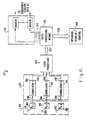
- VLS 20 A vehicle locating system (VSL) 20, in accordance with the present invention, is pictorially shown in FIG. 1.
- VLS 20 is operative over the entire Continental United States and may, therefore, be considered a nationwide vehicle locating system (NVSL).
- NVSL nationwide vehicle locating system
- VLS 20 is limited neither to the Continental United States nor to any other specific region and may be used to advantage in most geographical areas of the world, subject to certain limitations that will become apparent from the following description. Neither is VLS 20 limited to large, continental areas, but may be advantageously used in such smaller areas as states, counties and cities.
- VLS 20 is configured to provide vehicle location information at a remote, off-vehicle location, and does not specifically provide for vehicle location information to be made available to the vehicles associated with the VLS. Accordingly, a principal objective of the invention is to provide, at a comparatively low cost, location information regarding a large number of vehicles at a centralized control center from which the vehicle information can be communicated, by conventional, preexisting means, to such system subscribers as trucking, bus, vehicle rental and railroad companies or to other companies or individuals having an interest in being provided updated vehicle location information.
- VLS vehicle
- vehicle should be broadly construed to include not only automobiles, trucks and buses, but also virtually any type of movable object such as boats, ships, railroad engines, rolling stock, construction equipment, portable shelters and aircraft.
- present VLS is also adaptable for use with and by individuals.
- VLS 20 as described herein, importantly enables a relatively low per-vehicle implementing and operating cost by the use of small, low cost, standardized vehicle transmitters which randomly, with respect to each other (as opposed to synchronously), transmit radio frequency (RF) signals which are similar for each transmitter except for unique transmitter identification coding.
- RF radio frequency
- VLS 20 Illustrated in Fig. 1 as comprising VLS 20 is a central processing station or center 22 at which vehicle locations are computed from transmitted signal time differences of arrival (TDOA). Further comprising VLS 20 are at least first, second and third elevated radio signal relay stations 24, 26 and 28 which receive vehicle transmitter RF signals and relay or retransmitthese signals to processing center 22 for processing. Also comprising VLS 20 are a large number of what may be termed "vehicle transmitters", only three of which are shown in FIG. 1, being identified by the reference numbers 30, 32 and 34. The number of vehicle transmitters used in or accommodated by any specific VLS depends upon such factors as the size of the geographical region served by the VLS, the number of subscribers to the VLS service and the purpose and scope of the VLS involved. The number of vehicle transmitters may thus vary widely between, for example, a few hundred and several million. However, VLS 20 of the present invention is especially useful for very large numbers of vehicle transmitters because of its unique data handling capability.
- TDOA transmitted signal time differences of arrival
- VLS 20 Further comprising VLS 20 are one or more calibration or benchmark transmitters.
- Three such benchmark transmitters are depicted in Fig. 1, being identified by reference numbers 40, 42 and 44.
- These benchmark transmitters 40, 42 and 44 are ground-mounted in widely-spaced apart, fixed locations so as to cover the region served by VLS 20.
- benchmark transmitters 40, 42 and 44 are constructed similarly to vehicle transmitters 30, 32 and 34 and in any event transmit similar RF signals.
- These benchmark RF signals are relayed along with RF signals from vehicle transmitters 30, 32, 34 (etc.) by relay stations 24, 26 and 28 to processing station 22.
- the benchmark RF signals can be used to calibrate the system and to establish the exact locations of relay stations 24, 26 and 28 to enable compensation for any movement thereof from their "fixed" locations. It will, of course, be understood that knowledge of the precise locations of relaystations 24, 26 and 28 relative to control station 22 is necessary to enable accurate determination of the locations of the vehicle transmitters 30, 32, 34 (etc.) relative to a preestablished grid system or map.
- Vehicle transmitters 30, 32 and 34 are depicted, by way of example in FIG. 1, as being mounted on respective wheeled vehicles 30a, 32a and 34a. Also by way of example, relay stations 24, 26 and 28 are depicted in Fig. 1 as being mounted on respective artificial satellites 46, 48 and 50, which are in geosynchronous orbits above the region (for example, the Continental United States) served by VLS 20.
- relay stations 24, 26 and 28 on geosynchronous satellites 46, 48 and 50 (assuming proper satellite selection and positioning) advantageously enables each relay station 24, 26 and 28 to be in a line-of-sight relationship with processing station 22, with benchmark transmitters 40, 42 and 44 and ordinarily with all of vehicle transmitters 30, 32, 34 (etc.), thereby assuring good reception by the relay stations of signals transmitted by the benchmark and vehicle transmitters, and also ensuring good reception of the relayed signals by processing station 22.
- relay stations 24, 26 and 28 may be ground based, being, for example, installed in high mountain locations, atop tall buildings or on radio towers. Because relay stations 24, 26 and 28 are merely RF signal repeaters and perform no data processing, the stations are not large and, in the case of satellite mounting, do not require "dedicated" satellites, but can be carried aboard commercial satellites used principally for other purposes.
- FIG. 1 Also depicted in FIG. 1, but not comprising part of VLS 20, are two representative subscriber stations 60and 62 which are illustrated as being respectively connected, for communication purposes, to processing station 22 by preexisting telephone lines 64 and by a microwave or radio link 66. Ordinarily, many such subscriber stations would be connected by conventional communication links to processing station 22.
- Vehicle transmitters 30, 32, 34 are constructed as shown in FIG. 2, vehicle transmitter 30 being illustrated and described as representative of all vehicle transmitters and also of benchmark transmitters 40, 42 and 44.
- transmitter 30 Generally comprising transmitter 30 are a reference oscillator or "clock" 70, a sequencer or operation timer 72, memory means 74, a low pass filter 76, exciter means 78, a power amplifier 80, a pulse forming network 82 and an antenna 84.
- exciter means 78 are an L-band oscillator 86, a phase lock loop 88 and a summer 90.
- sequencer 72 such auxiliary equipment as a motion sensor 100, a crash sensor 102, vehicle anti-theft means 104 and manual message selecting means 106.
- Motion sensor 100 and crash sensor 102 preferably comprise conventional accelerometers which may be set or selected for different "g” levels of acceleration. Motion sensor 100 is preferably set for a much lower “g” level than crash sensor 102 so that a distinction can be made between normal "g” levels associated with vehicle movement and high "g” levels expected when a vehicle crashes.
- Anti-theft means 104 is any commercially available or custom vehicle anti-theft apparatus which provides an electric signal in response to vehicle intrusion, tampering or unauthorized movement.
- message selecting means 106 may comprise a conventional keyboard or switch (not shown) by means of which several prestored message codes may be selected for encoding in the RF transmission of associated vehicle transmitter 30.
- Sequencer 72 controls the RF signal repetition rate and the formatting of the RF signal.
- Memory means 74 which preferably comprises first and second PROMs (programmable read only memories) 110 and 112, respectively, and a data buffer 114, contains signal formatting information, including the transmitter identification code (stored in first PROM 110) and specific message codes (stored in second PROM 112). Codes for a limited number of such messages as “need assistance,” “accident,” and “out of service” may be stored in PROM 112 and may be automatically selected by signals from crash sensor 102, anti-theft means 104 or manually by manual message selecting means 106.
- Transmitter 30 is advantageously configured to provide an RF message signal 120 of the format depicted in Fig. 3.
- signal 120 may be 100 microseconds long and may include a 20 microsecond synchronization symbol 122 followed by six (6) data symbols 124, each of which may contain four (4) data bits or information and may be 10 microseconds long.
- Data symbols 124 are used to format the transmitter identification code or number, there being the possibility of 166 (16,777,216) possible vehicle identifications, which can be provided by data symbols 124.
- a four bit field symbol 126 also 10 microseconds long, follows the data symbols 124 and 16 codes are therefore available for message encoding. Some codes in field symbol 126 may alternatively be used for signal processing instructions. Following field symbol 126 may be a 10 microsecond processing symbol used for time tagging, as described below.
- signals 120 are preferably formatted by known “spreadspectrum” techniques. Such techniques, are, for example, described in "Spread Spectrum Systems” by R.C. Dixon, John Wiley and Sons, Publishers, 1976, and in the present case preferably provide a "chip” rate of about 6.4 million chips per second. Synchronization symbol 122 is thus sub-divided into 128 chips which comprise a pseudo-random pattern of binary ones and Zeros. By “pseudo-random” it is meant that the pattern of ones and zeros is quasi-random but the pattern is known.
- Each vehicle transmitter 30, 32, 34 (etc.) and each benchmark transmitter 40, 42 and 44 is configured to provide the same synchronization pattern of chips by which the beginning of each signal can be identified.
- Vehicle identification symbols 124 are similarly spread spectrum formatted, each being formed of 64 chips which are arranged in a specific pseudo-random manner of binary ones and zeros. Symbols 126 and 128 are similarly formatted.
- signal 120 transmitted by vehicle transmitter 30 is repeated at specific intervals (Fig. 4); however, field symbol 126 may be differently formatted to incorporate particular message codes, if provision is made for such coding.
- Signals 120 may, for example, be repeated at intervals of one minute so that the transmitter (vehicle) location information provided to system subscribers is always current.
- transmitters 30, 32, 34 (etc.) transmit signals 120 once every minute under normal "vehicle-in-motion" conditions, and that such signals are transmitted at times t1, t2, t3 and so forth, as is diagrammed in Fig. 4.
- Sequencer 70 is, however, also configured to provide a short initiating or control signal 138 at times t1- ⁇ t, t2- ⁇ t, t3- ⁇ t, and so forth.
- Theme control signals 138 are provided, over respective lines 140 and 142 (Fig.
- phase lock loop 88 and to pulse forming network 82 1), to phase lock loop 88 and to pulse forming network 82, and cause L-band oscillator 86 to attain the design frequency of operation (through operation of feed back loop 88) and cause pulse forming network 82 to be "fired” to provide (over a line 144) to power amplifier 80 a high power pulse of sufficient duration to enable outputting of signal 120. Due to this energy efficient configuration of transmitter 30, 32, 34 (etc.), a single alkaline battery of the D-cell type should operate the transmitter for about one year under normal conditions.
- Sequencer 72 may also be configured, in a manner known to those skilled in the art, to cause signals 120 to be transmitted at several different, predetermined repetition rates. As an illustration, provided an electric signal is input, over a line 146, by motion sensor 100 any time in the one minute interval between routinely-timed transmissions, sequencer 72 will continue transmitting signals 20 at a normal, exemplary once per minute rate. However, in the absence of any motion sensor signals, thereby indicating that the associated vehicle is not moving, sequencer 72 may automatically select a longer time interval (such as one hour) between signal transmissions, since less frequent vehicle location updating is required when the associated vehicle is not moving. Nevertheless, periodic updating of the vehicle location is still usually desirable to assure that the transmitter is properly functioning.
- a longer time interval such as one hour
- sequencer 72 could alternatively be configured to inhibit the transmission of any signal 120 when the vehicle is not in motion.
- Sequencer 72 may also be configured so that responsive to electronic signals, over lines 148 and 150, from crash sensor 102 and anti-theft means 104, the time intervals between transmission of signals 120 is reduced to less than one minute. Responsive to a crash indication, signals 120 might, for example, be transmitted every five seconds. Similarly, responsive to a vehicle tampering indication, the signal transmissions might be transmitted every ten seconds. When configured in this manner to provide different, preestablished transmission periods for different conditions, information as to vehicle status is effectively "encoded" into signals 120 without actually changing the format of the signals. Such repetition rate coding is advantageous if actual encoding of messages into signals 120 is not permitted by airwave regulating authorities, such as the F.C.C, or is otherwise not considered desirable.
- Transmitters 30, 32, 34 can, with known low-cost construction techniques be made sufficiently small to be installed in a package 150 (FIG. 5) only about five inches in diameter and only about one and one half inches thick.
- Antenna 84 may correspondingly comprise a short wire monopole antenna projecting from package 150.
- a narrow, apertured flange 152 around the base of package 150 enables convenient mounting of the package to a vehicle (or other object).
- transmitters 30, 32, 34 (etc.) can alternatively be mounted on (or concealed in) small objects such as shipping cartons, luggage and briefcases, and may even be carried by individuals on their person, if so desired.
- the size of package 150 may be further reduced.
- transmitters 30, 32, 34 (etc.) to be integrated into other electronic equipment, such as automobile AM/FM radios or CB radios.
- Relay stations 24, 26 and 28 relay signals 120 from vehicle transmitters 30, 32, 34, (etc.) and benchmark transmitters 40, 42 and 44 to processing station 22 for processing into vehicle location information.
- relay stations 24, 26 and 28 preferably comprise signal repeaters of conventional design, known in the art.
- the apparatus selected should be small and light in weight, should have low power consumption and should be especially reliable in operation. Because relay stations 24, 26 and 28 are of known, conventional configuration further description of these stations is neither considered necessary nor is provided herein.
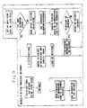
- Central processing station 22 comprises generally signal receiving means 160, signal correlating means 162, a time-delay-of-arrival (TDOA) processor 164, a data processor or data processing means 166, operator display and control means 168 and subscriber interfacing means 170.
- signal receiving means 160 are respective first, second and third directional antennas 178, 180 and 182, which are aimed towards corresponding relay stations 24, 26 and 28 (FIG. 1) for separately receiving relayed signals 120 therefrom.
- Respectively associated with antennas 178, 180 and 182 are similar first, second and third RF receivers 184, 186 and 188, each of which are of conventional design and therefore require no further description.
- first, second and third signal correlators 190, 192 and 194 comprise signal correlating means 162.
- Spread spectrum signals 120 received by first receiver 184, via first antenna 178, are serially fed into first signal correlator 190 over a correlator input line 196.
- second correlator 192 receives spread spectrum signals 120 from second receiver 198 over a signal correlator input line 186 and third signal correlator 194 receives signals 120 from third receiver 188 over line 200.
- Signal correlators 190, 192 and 194 are configured for sorting out signals 120 which may overlap one another due to near-simultaneous, random transmissions from different transmitters 30, 32, 34, (etc.) and 40, 42 and 44 so that corresponding time-differences-of-arrival can be determined by TDOA processor 164 and individual transmitter locations can be determined, in the manner described below.
- FIG. 7 illustrates, in functional block diagram form, one manner in which signal correlators 190, 192 and 194 may advantageously be implemented, first signal correlator 190 being shown as representative of all three signal correlators.
- signal correlator 190 as shown, are a synchronization correlator 210, a thresholder 212, first and second data correlators 214 and 216 and an Nth data correlator 218 (there being a total of N data correlators arranged in parallels only the first, second and Nth data correlators being shown).
- Signals, in spread spectrum format, which are received by first receiver 184 are fed, over line 196, to the inputs of synchronization correlator 210 and to first through Nth data correlators 214-218.
- Outputs from first through Nth data correlators 214-218 are fed, over a bus or multiple line 220, to an input of TDOA processor 164.
- Synchronization correlator 210 comprises, as shown in Fig. 8, an input register 230 and a store register 232; each such register has of a number of cells equal to the number of chips in signal synchronizing symbol 122 (FIG. 3). As above-described, the number of chips in synchronizing symbol 122 may be 168. Permanently stored in store register 232 is the specific pseudo-random synchronizing symbol code used by all signals 120.
- An RF signal 234 (which comprises a string of single or overlapped transmitter signals 120) received by receiver 184 from relay station 24 is provided over line 196 into input register 230.
- the content of each cell of the register is compared in a known manner by comparing means 236, with the content of each corresponding cell in store register 232.
- the thresholder outputs a correlation chip on a line 238 to data correlators 214-218.
- One such correlation chip is provided by thresholder 212 for each signal chip fed into input register 230.
- the string of correlation chips provided by thresholder 212 make up a thresholder output signal 240.
- a maximum value correlation chip will be provided by thresholder 212 when the contents of all cells of input register 230 correlate with the contents of all cells in store register 232. This occurs only when a complete synchronization symbol 122 has been input into register 230 and thereby indicates that the beginning of a signal 120 has been received.
- signal 234 provided through receiver 184 to input register 230 may frequently or occasionally comprise two or more overlapping signals 120 and may, at times, include overlapping synchronization symbols 122 from different transmitters. Typically, synchronization correlation will be poorer when overlapping synchronization symbols 122 are present than when only one such symbol is present. Synchronization symbol discrimination in the presence of overlapping signals 120 is preferably provided by conventional "thresholding" techniques. A correlation threshold 242 may thus be established against which correlation chips provided by thresholder 212 are tested.
- Threshold 242 is established at a level such that when the level is exceeded by a correlation chip output of thresholder 212, a high probability exists that a synchronization symbol has, in fact, been input into register 230. Similarly, a high probability exists that if the correlation chips are below threshold 242 a synchronization chip has not been input into input register 230. As in the case of other thresholding situations, if threshold 242 is set too high, synchronization symbols 122 may fail to be detected and some signals 120 may be missed; on the other hand, if threshold 242 is set too low, false indications of synchronization symbols having been received into input register 230 may be provided. In either event, however, frequent transmissions of signals 120 by each transmitter 30, 32, 34 (etc) should still enable accurate transmitter (vehicle) locations determinations to be made by processing station 22.
- Data correlators 214-218 are connected and configured for receiving signal 234 from receiver 184 in spread spectrum format and for outputting corresponding, non-spread spectrum signals 244 over bus 220 to TDOA processor 166 (FIG. 7). Towards this end, whenever a correlation chip provided by thresholder 212 exceeds threshold 242, the first available one of data correlators 214-218 is enabled to receive the rest of signal 120 that has just been identified by synchronization symbol correlation in synchronization correlator 210. A sufficient number of data correlators 214-218 are provided to accommodate the maximum number of overlapping signals 120 that are expected to occur in correlator 190. If, however, no data correlator is available to accept a signal 120, the signal is automatically discarded. Again, because of the frequent repetition of signal transmissions from each transmitter 30, 32, 34 (etc.) an occasional discarding of a signal 120 is not considered to significantly affect operation of VLS 20.
- each identification symbol 126 of each transmitted signal 120 comprises four binary bits
- sixteen possible bit patterns (0000, 0001, 0010...1111) exist for each such symbol.
- the correlation is checked between the contents of an input register (similar to input register 130) and the contents of sixteen store registers (each similar to store register 232) in which the sixteen different binary arrangements are stored.
- the store register "number" is output over bus 220 to TDOA processor 164
- a hexadecimal system is conveniently used, the hexadecimal representations being as shown in Table 1, below.
- data correlations 214-218 identify and decode message codes (if any) encoded into the four bits of message symbol 126, and include such message information in output signal 244 to TDOA processor 164.
- all 166 (16,777,216) possible transmitter identification numbers permitted by six symbols 124, each having four bits, can be represented by six hexadecimal "digits".
- the decimal number 10,705,823 can be represented hexadecimally as "A35B9F".
- Data correlators 214-218 provide such processed signals, in non-spread spectrum format, over bus 242 to TDOA processor 166 (FIG. 7).
- data correlators 214-218 encode time of signal arrival information into signal symbol 126.
- a clock 246 provides clock signals (ck) to each of data correlators 214-218.
- second correlator 192 operates on signals 120 received from second relay station 26 by receiver 186 and provides time-tagged, decoded signals to TDOA processor 164 over a bus 248 and third correlator 194 operates on signals 120 received from relay station 26 by receiver 188 and provides time-tagged signals to the TDOA processor over a bus 250 (FIG. 6).
- TDOA processor 164 sorts the time-tagged signals from first, second and third correlators 190, 192 and 194 according to transmitter identification number and time of arrival.
- a set of three time-tagged signals which represent the same signal 120 separately relayed by stations 24, 26 and 28, and thus arriving at three different times in correlators 190, 192 and 194, are found and the times of arrival are within a specific time range assuring that the signals all originated at the same time and are not from different transmissions, pairs of time differences of arrival are computed by considering different pairs of signals in each set. This time difference of arrival data is provided by TDOA processor 164 to data processor 166 over a bus 252.
- data processing means 166 which may comprise a general purpose computer, computes the location of the corresponding transmitter 30, 32, 34 (etc.) in accordance with known techniques. These known techniques compute the intersections of two hyperbolic surfaces of revolution with the transmitter location being on the line of intersection of such surfaces; in the described embodiment having three relay stations 24, 26 and 28, separate altitude information is required to establish a point on the intersection line. For surface vehicles, such altitude is assumed, for example, to be zero feet. To establish the three dimensional coordinates for non-surface vehicles (e.g. aircraft) a fourth relay station, similar to stations 24-28, may be provided.
- the transmitter identification is cross-checked with stored transmitter-vehicle identification and vehicle location information is provided, through a bus 254 and interface means 170, to appropriate system subscriber stations 60 and 62.
- vehicle location information may be provided, over a bus 256, to operator display means 168 (FIG. 6).
- Data processing means 166 further enable the counting of the repetition rate at which signals are transmitted by individual ones of transmitters 30, 32, 34 (etc.), "decoding" of signal repetition rate messages (such as “vehicle-not-in-motion,” “vehicle crash” and “vehicle intrusion/theft") and providing this information to system subscribers 60 and 62. Likewise, data processing means 166 decode messages (if any) encoded into signal symbols 126 and provides such information to subscribers 60 and 62.
- benchmark transmitters 40, 42 and 44 importantly provides calibration information for VLS 20.
- the locations of benchmark transmitters 40, 42 and 44 are determined in the manner described for obtaining the locations of vehicle transmitters 30, 32, 34 (etc.).
- the computed benchmark locations are correlated, by data processing means 166, with benchmark transmitter surveyed location information stored in the data processing means.
- benchmark transmitters 40, 42 and 44 have not been moved,
- relay stations 24, 26 and 28, whose locations are used in computing transmitter locations have not moved relative to the geographical region covered, and
- data processing portions of VLS 20 are properly functioning.
- three relay stations 24, 26 and 28 have hereinabove been described, three such relay stations being sufficient to provide two dimensional, ground-level location information, as is usually satisfactory for ground vehicles. However, for vehicles in mountainous regions and for aircraft, three dimensional location information is, or may be, required.
- VLS 20 can then be expanded, and it is within the scope of the invention to so expand the VLS, to incorporate a fourth relay station similar to relay stations 24, 26 and 28 and to include corresponding receiving antenna, similar to antennas 178, 180 and 182; a corresponding receiver, similar to receivers 184, 186 and 188 and a corresponding, fourth correlator similar to correlators 190, 192 and 194 and to expand the TDOA and data processing capabilities to handle additional computations necessary for determining a third location coordinate.
- a fourth relay station similar to relay stations 24, 26 and 28 and to include corresponding receiving antenna, similar to antennas 178, 180 and 182; a corresponding receiver, similar to receivers 184, 186 and 188 and a corresponding, fourth correlator similar to correlators 190, 192 and 194 and to expand the TDOA and data processing capabilities to handle additional computations necessary for determining a third location coordinate.
- correlation means 162, TDOA processor 164 and data processing means 166 have been illustrated in the Figures and have been described as being separate. In practice, however, all such portions of processing station 22 may be combined and may comprise a general purpose computer.
- the present inventors have estimated that the individual cost of transmitters 30, 32, 34, (etc.) and 40, 42 and 44, in production quantities, will be less than 100 dollars, that the cost of central processing station 22 will be about three million dollars, (exclusive of property and buildings) and that the per-year cost of relay stations 24, 26 and 28 will be about sixteen million dollars. From these cost estimates, it is evident that the per-transmitter cost (that is, per-vehicle cost) is very small provided a sufficiently large number of vehicles are covered by VLS 20. It is this unique ability of the present VLS 20 to handle very large numbers of transmitters that importantly permits the system to be economically attractive to subscribers.
Landscapes
- Engineering & Computer Science (AREA)
- Radar, Positioning & Navigation (AREA)
- Remote Sensing (AREA)
- Physics & Mathematics (AREA)
- General Physics & Mathematics (AREA)
- Computer Networks & Wireless Communication (AREA)
- Mobile Radio Communication Systems (AREA)
Abstract
Description
- The present invention relates generally to apparatus and methods for remotely determining the location of such movable objects as automobiles, trucks, railway cars, ships and boats, (generically referred to as vehicles), and more particularly to apparatus and methods for determining the locations of such objects at a centralized control station by the processing of radio frequency transmissions from transmitters mounted on the objects.
- Information concerning the location of surface vehicles, ships, airplanes and the like is important for many reasons, including business, safety and security reasons. As is well known, the apparatus and methods used to determine the location of such objects have varied greatly over the centuries and have been greatly improved in accuracy and sophistication during the past several decades.
- Historically, for example, early ocean navigators relied upon often extensive knowledge of ocean currents, prevailing wind directions and the positions of stars in the sky to determine their locations when out of sight of familiar landmarks, and to thereby chart their paths to intended destinations. Subsequent navigators had available chronographs, compasses, astrolabes and sextants by which to determine their approximate positions. Still more recently, ocean and air navigation has benefited from various types of radio location apparatus, including LORAN and variations thereof. Modern ships and aircraft may presently rely upon radar, inertial navigation apparatus and satellite navigation systems by which positional information can usually be determined with great precision.
- Land navigation has generally been easier than ocean and air navigation, at least after traveled regions of the earth were accurately mapped. Known landmarks could always be relied up in determining positional locations on land; in unmapped or unfamiliar regions, ocean navigation apparatus and methods have been used.
- Presently, at least under normal circumstances, the knowledge of one's location in most habited regions of the world is relatively easy for a vehicle operator to determine from available maps or by inquiry from local inhabitants. It is, however, generally a more difficult and costly problem for control centers remote from the vehicles to determine, at all practical times, the location of a number of vehicles which may be under direct or indirect supervision by the control center. Even assuming that the vehicle operators themselves know their vehicle locations, difficulties exist in continually providing such location information to a control center which may be responsible for supervising a great many vehicles.
- Telephone communication of vehicle position on a periodic basis is, of course, possible and may, for example, be used by sales personnel who may otherwise routinely telephone their headquarters to report their activities and obtain messages. In many instances, however, frequent telephone communication is impractical and may, in any event, be very costly. Verbal communication from vehicle operators to a control center, by use of on-board, short wave radio transmitters, is frequently used to provide local area positions of trucks, taxi cabs, police cars, ambulances and fire trucks to central dispatchers. However, such radio communications are usually impractical for long ranges, are relatively costly on a per-vehicle basis and require operator intervention.
- Various vehicle location systems of a more sophisticated nature have been disclosed, for example, In US-A-3568161, US-A-3646580, US-A-3714573, US-A-4215345 (MacDoran) and US-A-4359733 (O'Neill). The O'Neill patent discloses a satellite-based vehicle position determining system which utilizes coded radio signals from transponders carried aboard land vehicles and aircraft. Relay stations on artificial satellites are used to relay the radio signals from the vehicles and/or aircraft to a remote control station which uses time of signal arrival to determine vehicle or aircraft position. The radio signals from the vehicles or aircraft are, however, provided only in response to an interrogation signal sent to transponders on the vehicle and aircraft. Thus, in such systems, two-way communication with the vehicles and aircraft is required and each vehicle and aircraft thus requires both a transmitter and a receiver. When such equipment is already available for other purposes on the vehicles and aircraft, low vehicle location equipment costs may result. However, in most instances involving land vehicles, appropriate radio communication receivers and transmitters are not already provided and the cost of adding such equipment must accordingly be borne by the vehicle location system as part of the overall system cost.
- The MacDoran patent discloses a vehicle locating system based upon the detection by several stations of radio signals transmitted from vehicles. Precise, time-formatted radio signal receptions from each station are retransmitted, after time-tagging, to a central station where the signals are cross correlated with all other signals to determine the time-differences-of-arrival from the vehicle for all possible station pairs. The central station processes the time differences of arrival data to locate the vehicle's position at the intersection of derived hyperboloids. As disclosed by MacDoran, noise characteristics of each transmitted pulse are utilized to determine the time differences of arrival from all pairs of receiving stations, the presence or absence of cross correlation signals being used for decoding the vehicle identity. All receiving stations must, however, be synchronized by a calibration beacon and the system is incapable of handling overlapping signals, the latter factor limiting the system, as stated in the disclosure, to no more than about 100 vehicles.
- There exists, therefore, a need for a comparatively low cost vehicle locating system that has the capability for handling many thousands or millions of vehicles, as well as for a vehicle locating system that does not require special synchronisation and does not require costly two-way communication apparatus.
- According to the present invention, there is provided a vehicle locating system for remotely determining the locations of a comparatively large number of vehicles operating within a specific geographical region, the vehicle locating system comprising:
- a. a number of similar, automated radio frequency transmitters adapted for mounting on vehicles for transmitting radio frequency signals;
- b. first, second and third elevated radio signal relay stations for receiving the radio frequency signals from said transmitters and for relaying said received signals, the relay stations being spaced apart from one another in known locations relative to said geographical region covered by the vehicle locating system; and
- c. a central processing station having means for separately receiving the relayed radio frequency signals from each of the relay stations, means for maintaining the separation of the relayed signals from one another, means for establishing the time of arrival and identity of each signal at said processing station and means for determining from time differences of arrival (TDOA) arrival of the signals from the relay stations a location of each transmitter that is transmitting signals;
characterised in that each of said transmitters is configured for transmitting radio frequency signals that are all similar for all of said transmitters except that each transmitter has means for encoding onto the signal transmitted thereby a unique transmitter identification code, each of the transmitters including means for encoding a spread spectrum synchronization code into each transmitted signal, the spread spectrum synchronisation code being the same for each transmitter, each of the transmitters having means for causing the transmitted signals to be repeated at predetermined intervals, each of the transmitters operating independently of one another and hence in a random manner relative to one another, and
the central processing station means for maintaining the separation of the relayed signals from one another includes means for correlating the spread spectrum synchronization code with a corresponding stored synchronization code in a manner enabling individual signals to be identified even in the presence of overlapping signals. - In an embodiment of the invention, at least some of the transmitters include means for enabling the repetition rate of the signals to be varied to enable communication of messages from the transmitters to the central processing station by merely changing the signal repetition rate. In such case, motion sensing means may be associated with some of the transmitters. Responsive to the motion sensing means, the means for varying the signal repetition rate may cause the signals to be repeated at a first rate when the motion sensing means indicates that the transmitter is at rest and at a second repetition rate when the motion sensing means indicates that the transmitter is moving. The signal repetition rate associated with the transmitter being at rest may be substantially less than the repetition rate when the transmitter is moving so that signal traffic may be reduced over that which would otherwise occur if all the transmitters transmitted at the moving transmitter rate.
- Vehicle anti-theft means may be included for some vehicles whose transmitters have signal repetition rate varying capability. Responsive to electric signals from the vehicle anti-theft means, the transmitter may be caused to transmit signals at a predetermined repetition rate associated with a vehicle tampering situation so that such information can be provided by the central processing station to subscribers. In addition, or alternatively, according to an embodiment of the invention, crash sensing means may be provided on vehicles equipped with variable repetition rate transmitters. Responsive to an output from the crash sensing means that indicates the probability of a vehicle crash, the signal transmission rate is shifted to a predetermined rate associated with a crash situation. Still further, some transmitters may include means for selectively encoding preestablished messagecodes into the transmitted signals for decoding at the central processing station.
- It is still further preferred that the vehicle location system includes at least one benchmark transmitter mounted at a known, fixed location relative to the geographical region covered by the system. The benchmark transmitter is configured to transmit radio frequency signals similar to those transmitted by the vehicle-mounted transmitters, signals from the benchmark transmitter being processed in the same manner as those of the vehicle-mounted transmitters to determine the location of the benchmark transmitter. Differences between the actual, known location of the benchmark transmitter and the computed location thereof can be used to calibrate the system, including the locations of the relay stations.
- Because a very large number of vehicles can be accommodated by the vehicle locating system of the present invention, the per-vehicle procurement and operating costs of the system can be very low and, therefore, attractive to system subscribers.
- The present invention can be better understood by a consideration of the drawings in which:
- FIG. 1 is a pictorial drawing depicting a vehicle locating system (VLS) in accordance with the present invention, showing, by way of illustrative example, a nationwide VLS covering the Continental United States:
- FIG. 2 is a functional block diagram of a representative radio frequency (RF) transmitter used in the VLS of FIG. 1 showing major parts of the transmitter;
- FIG. 3 is a diagram of the RF signal transmitted by the transmitter of FIG. 2 showing the signal divided into its various symbols and showing the manner in whichspread spectrum techniques are applied to represent the synchronization symbol of the signal by a large number of signal elements, called chips;
- FIG. 4 is a diagram depicting the typical output of a sequencer portion of the transmitter;
- FIG. 5 is a perspective drawing of a short, cylindrical package in which the transmitter of FIG. 2 can be mounted and by means of which the transmitter can be mounted on a vehicle or other object;
- FIG. 6 is a functional block diagram of the central data processing station at which transmitter (vehicle) location determinations are made;
- FIG. 7 is a functional block diagram of a representative signal correlator used in the central data processing station;
- FIG. 8 is a functional block diagram of a signal synchronization correlator portion of the correlator of FIG. 7; and
- FIG. 9 is a flow diagram of the operation of the central processing station.
- A vehicle locating system (VSL) 20, in accordance with the present invention, is pictorially shown in FIG. 1. As depicted, and by way of illustrative example of the invention, VLS 20 is operative over the entire Continental United States and may, therefore, be considered a nationwide vehicle locating system (NVSL). However, VLS 20 is limited neither to the Continental United States nor to any other specific region and may be used to advantage in most geographical areas of the world, subject to certain limitations that will become apparent from the following description. Neither is VLS 20 limited to large, continental areas, but may be advantageously used in such smaller areas as states, counties and cities.
- As more particularly described below, VLS 20 is configured to provide vehicle location information at a remote, off-vehicle location, and does not specifically provide for vehicle location information to be made available to the vehicles associated with the VLS. Accordingly, a principal objective of the invention is to provide, at a comparatively low cost, location information regarding a large number of vehicles at a centralized control center from which the vehicle information can be communicated, by conventional, preexisting means, to such system subscribers as trucking, bus, vehicle rental and railroad companies or to other companies or individuals having an interest in being provided updated vehicle location information.
- It is emphasized that the term "vehicle" as used herein should be broadly construed to include not only automobiles, trucks and buses, but also virtually any type of movable object such as boats, ships, railroad engines, rolling stock, construction equipment, portable shelters and aircraft. Moreover, the present VLS is also adaptable for use with and by individuals.
-
VLS 20, as described herein, importantly enables a relatively low per-vehicle implementing and operating cost by the use of small, low cost, standardized vehicle transmitters which randomly, with respect to each other (as opposed to synchronously), transmit radio frequency (RF) signals which are similar for each transmitter except for unique transmitter identification coding. - Illustrated in Fig. 1 as comprising
VLS 20 is a central processing station orcenter 22 at which vehicle locations are computed from transmitted signal time differences of arrival (TDOA). Further comprisingVLS 20 are at least first, second and third elevated radiosignal relay stations 24, 26 and 28 which receive vehicle transmitter RF signals and relay or retransmitthese signals toprocessing center 22 for processing. Also comprisingVLS 20 are a large number of what may be termed "vehicle transmitters", only three of which are shown in FIG. 1, being identified by thereference numbers VLS 20 of the present invention is especially useful for very large numbers of vehicle transmitters because of its unique data handling capability. - Further comprising
VLS 20 are one or more calibration or benchmark transmitters. Three such benchmark transmitters are depicted in Fig. 1, being identified byreference numbers benchmark transmitters VLS 20. Preferably, but not necessarily,benchmark transmitters vehicle transmitters vehicle transmitters relay stations 24, 26 and 28 toprocessing station 22. Because the locations ofbenchmark transmitters relay stations 24, 26 and 28 to enable compensation for any movement thereof from their "fixed" locations. It will, of course, be understood that knowledge of the precise locations ofrelaystations 24, 26 and 28 relative to controlstation 22 is necessary to enable accurate determination of the locations of thevehicle transmitters -
Vehicle transmitters wheeled vehicles 30a, 32a and 34a. Also by way of example,relay stations 24, 26 and 28 are depicted in Fig. 1 as being mounted on respectiveartificial satellites VLS 20. The mounting ofrelay stations 24, 26 and 28 ongeosynchronous satellites relay station 24, 26 and 28 to be in a line-of-sight relationship withprocessing station 22, withbenchmark transmitters vehicle transmitters station 22. - However, for more localized VLS's all or some of
relay stations 24, 26 and 28 may be ground based, being, for example, installed in high mountain locations, atop tall buildings or on radio towers. Becauserelay stations 24, 26 and 28 are merely RF signal repeaters and perform no data processing, the stations are not large and, in the case of satellite mounting, do not require "dedicated" satellites, but can be carried aboard commercial satellites used principally for other purposes. - Also depicted in FIG. 1, but not comprising part of
VLS 20, are two representativesubscriber stations 60and 62 which are illustrated as being respectively connected, for communication purposes, toprocessing station 22 by preexistingtelephone lines 64 and by a microwave orradio link 66. Ordinarily, many such subscriber stations would be connected by conventional communication links toprocessing station 22. -
Vehicle transmitters vehicle transmitter 30 being illustrated and described as representative of all vehicle transmitters and also ofbenchmark transmitters transmitter 30 are a reference oscillator or "clock" 70, a sequencer oroperation timer 72, memory means 74, alow pass filter 76, exciter means 78, apower amplifier 80, apulse forming network 82 and anantenna 84. In turn, shown comprising exciter means 78 are an L-band oscillator 86, aphase lock loop 88 and asummer 90. There may be connected tosequencer 72 such auxiliary equipment as amotion sensor 100, acrash sensor 102, vehicle anti-theft means 104 and manualmessage selecting means 106. -
Motion sensor 100 andcrash sensor 102 preferably comprise conventional accelerometers which may be set or selected for different "g" levels of acceleration.Motion sensor 100 is preferably set for a much lower "g" level thancrash sensor 102 so that a distinction can be made between normal "g" levels associated with vehicle movement and high "g" levels expected when a vehicle crashes. Anti-theft means 104 is any commercially available or custom vehicle anti-theft apparatus which provides an electric signal in response to vehicle intrusion, tampering or unauthorized movement. In turn, message selecting means 106 may comprise a conventional keyboard or switch (not shown) by means of which several prestored message codes may be selected for encoding in the RF transmission of associatedvehicle transmitter 30. -
Sequencer 72 controls the RF signal repetition rate and the formatting of the RF signal. Memory means 74, which preferably comprises first and second PROMs (programmable read only memories) 110 and 112, respectively, and adata buffer 114, contains signal formatting information, including the transmitter identification code (stored in first PROM 110) and specific message codes (stored in second PROM 112). Codes for a limited number of such messages as "need assistance," "accident," and "out of service" may be stored inPROM 112 and may be automatically selected by signals fromcrash sensor 102, anti-theft means 104 or manually by manualmessage selecting means 106. -
Transmitter 30 is advantageously configured to provide an RF message signal 120 of the format depicted in Fig. 3. As so depicted, signal 120 may be 100 microseconds long and may include a 20microsecond synchronization symbol 122 followed by six (6)data symbols 124, each of which may contain four (4) data bits or information and may be 10 microseconds long.Data symbols 124 are used to format the transmitter identification code or number, there being the possibility of 16⁶ (16,777,216) possible vehicle identifications, which can be provided bydata symbols 124. - A four
bit field symbol 126, also 10 microseconds long, follows thedata symbols 124 and 16 codes are therefore available for message encoding. Some codes infield symbol 126 may alternatively be used for signal processing instructions. Followingfield symbol 126 may be a 10 microsecond processing symbol used for time tagging, as described below. - To enable processing a large number of transmitter signals which may be only slightly separated in time, signals 120 are preferably formatted by known "spreadspectrum" techniques. Such techniques, are, for example, described in "Spread Spectrum Systems" by R.C. Dixon, John Wiley and Sons, Publishers, 1976, and in the present case preferably provide a "chip" rate of about 6.4 million chips per second.
Synchronization symbol 122 is thus sub-divided into 128 chips which comprise a pseudo-random pattern of binary ones and Zeros. By "pseudo-random" it is meant that the pattern of ones and zeros is quasi-random but the pattern is known. Eachvehicle transmitter benchmark transmitter Vehicle identification symbols 124 are similarly spread spectrum formatted, each being formed of 64 chips which are arranged in a specific pseudo-random manner of binary ones and zeros.Symbols - In the preferred embodiment described herein, signal 120 transmitted by
vehicle transmitter 30 is repeated at specific intervals (Fig. 4); however,field symbol 126 may be differently formatted to incorporate particular message codes, if provision is made for such coding.Signals 120 may, for example, be repeated at intervals of one minute so that the transmitter (vehicle) location information provided to system subscribers is always current. - Assuming, by way of example, a nominal repetition rate of one
signal 120 per minute per transmitter, it is evident that for signals having a length of 100 microseconds, 600,000 non-overlapping signals can be transmitted each minute. However, becausesynchronization symbol 122 is only 20 microseconds long, 3 million non-overlapping synchronization symbol portions ofsignals 120 can be transmitted each minute and, because of the ability to data discriminate, it is estimated that at least about 6 milliontransmitters single VLS 20. - For purposes of illustrating the present invention, it may be assumed that
transmitters signals 120 once every minute under normal "vehicle-in-motion" conditions, and that such signals are transmitted at times t₁, t₂, t₃ and so forth, as is diagrammed in Fig. 4.Sequencer 70 is, however, also configured to provide a short initiating or control signal 138 at times t₁-Δt, t₂-Δt, t₃-Δt, and so forth. Theme control signals 138 are provided, overrespective lines 140 and 142 (Fig. 1), to phaselock loop 88 and topulse forming network 82, and cause L-band oscillator 86 to attain the design frequency of operation (through operation of feed back loop 88) and causepulse forming network 82 to be "fired" to provide (over a line 144) to power amplifier 80 a high power pulse of sufficient duration to enable outputting ofsignal 120. Due to this energy efficient configuration oftransmitter -
Sequencer 72 may also be configured, in a manner known to those skilled in the art, to causesignals 120 to be transmitted at several different, predetermined repetition rates. As an illustration, provided an electric signal is input, over aline 146, bymotion sensor 100 any time in the one minute interval between routinely-timed transmissions,sequencer 72 will continue transmittingsignals 20 at a normal, exemplary once per minute rate. However, in the absence of any motion sensor signals, thereby indicating that the associated vehicle is not moving,sequencer 72 may automatically select a longer time interval (such as one hour) between signal transmissions, since less frequent vehicle location updating is required when the associated vehicle is not moving. Nevertheless, periodic updating of the vehicle location is still usually desirable to assure that the transmitter is properly functioning. This reduced transmission rate by transmitters mounted on non-moving vehicles reduces overall transmission traffic, thereby enabling a greater number of vehicles to be included in VLS20 than might otherwise be possible. Of course,sequencer 72 could alternatively be configured to inhibit the transmission of anysignal 120 when the vehicle is not in motion. -
Sequencer 72 may also be configured so that responsive to electronic signals, overlines crash sensor 102 and anti-theft means 104, the time intervals between transmission ofsignals 120 is reduced to less than one minute. Responsive to a crash indication, signals 120 might, for example, be transmitted every five seconds. Similarly, responsive to a vehicle tampering indication, the signal transmissions might be transmitted every ten seconds. When configured in this manner to provide different, preestablished transmission periods for different conditions, information as to vehicle status is effectively "encoded" intosignals 120 without actually changing the format of the signals. Such repetition rate coding is advantageous if actual encoding of messages intosignals 120 is not permitted by airwave regulating authorities, such as the F.C.C, or is otherwise not considered desirable. -
Transmitters Antenna 84 may correspondingly comprise a short wire monopole antenna projecting frompackage 150. A narrow,apertured flange 152 around the base ofpackage 150 enables convenient mounting of the package to a vehicle (or other object). Because of its small package size,transmitters package 150 may be further reduced. Moreover, it is within the scope of the present invention, fortransmitters -
Relay stations 24, 26 and 28 relay signals 120 fromvehicle transmitters benchmark transmitters processing station 22 for processing into vehicle location information. Accordingly,relay stations 24, 26 and 28 preferably comprise signal repeaters of conventional design, known in the art. When, however,relay stations 24, 26 and 28 are to be mounted onto satellites, the apparatus selected should be small and light in weight, should have low power consumption and should be especially reliable in operation. Becauserelay stations 24, 26 and 28 are of known, conventional configuration further description of these stations is neither considered necessary nor is provided herein. -
Central processing station 22, as shown in block diagram form in FIG. 6, comprises generally signal receiving means 160, signal correlating means 162, a time-delay-of-arrival (TDOA)processor 164, a data processor or data processing means 166, operator display and control means 168 and subscriber interfacing means 170. In turn comprising signal receiving means 160 are respective first, second and thirddirectional antennas relay stations 24, 26 and 28 (FIG. 1) for separately receiving relayedsignals 120 therefrom. Respectively associated withantennas third RF receivers - Similar, first, second and
third signal correlators first receiver 184, viafirst antenna 178, are serially fed intofirst signal correlator 190 over acorrelator input line 196. Similarly,second correlator 192 receives spread spectrum signals 120 fromsecond receiver 198 over a signalcorrelator input line 186 andthird signal correlator 194 receivessignals 120 fromthird receiver 188 overline 200.Signal correlators signals 120 which may overlap one another due to near-simultaneous, random transmissions fromdifferent transmitters TDOA processor 164 and individual transmitter locations can be determined, in the manner described below. - FIG. 7 illustrates, in functional block diagram form, one manner in which signal
correlators first signal correlator 190 being shown as representative of all three signal correlators. Comprisingsignal correlator 190, as shown, are asynchronization correlator 210, athresholder 212, first and second data correlators 214 and 216 and an Nth data correlator 218 (there being a total of N data correlators arranged in parallels only the first, second and Nth data correlators being shown). - Signals, in spread spectrum format, which are received by
first receiver 184 are fed, overline 196, to the inputs ofsynchronization correlator 210 and to first through Nth data correlators 214-218. Outputs from first through Nth data correlators 214-218 are fed, over a bus ormultiple line 220, to an input ofTDOA processor 164. -
Synchronization correlator 210 comprises, as shown in Fig. 8, aninput register 230 and a store register 232; each such register has of a number of cells equal to the number of chips in signal synchronizing symbol 122 (FIG. 3). As above-described, the number of chips in synchronizingsymbol 122 may be 168. Permanently stored in store register 232 is the specific pseudo-random synchronizing symbol code used by allsignals 120. - An RF signal 234 (which comprises a string of single or overlapped transmitter signals 120) received by
receiver 184 fromrelay station 24 is provided overline 196 intoinput register 230. As each chip ofsignal 234 is fed intoregister 230, the content of each cell of the register is compared in a known manner by comparingmeans 236, with the content of each corresponding cell in store register 232. As each set of 168 correlating inputs are received bythresholder 212, the thresholder outputs a correlation chip on aline 238 to data correlators 214-218. One such correlation chip is provided bythresholder 212 for each signal chip fed intoinput register 230. The string of correlation chips provided bythresholder 212 make up athresholder output signal 240. - A maximum value correlation chip will be provided by
thresholder 212 when the contents of all cells ofinput register 230 correlate with the contents of all cells in store register 232. This occurs only when acomplete synchronization symbol 122 has been input intoregister 230 and thereby indicates that the beginning of asignal 120 has been received. - When
VLS 20 includes a very large number oftransmitters receiver 184 to input register 230 may frequently or occasionally comprise two or more overlappingsignals 120 and may, at times, include overlappingsynchronization symbols 122 from different transmitters. Typically, synchronization correlation will be poorer when overlappingsynchronization symbols 122 are present than when only one such symbol is present. Synchronization symbol discrimination in the presence of overlappingsignals 120 is preferably provided by conventional "thresholding" techniques. Acorrelation threshold 242 may thus be established against which correlation chips provided bythresholder 212 are tested.Threshold 242 is established at a level such that when the level is exceeded by a correlation chip output ofthresholder 212, a high probability exists that a synchronization symbol has, in fact, been input intoregister 230. Similarly, a high probability exists that if the correlation chips are below threshold 242 a synchronization chip has not been input intoinput register 230. As in the case of other thresholding situations, ifthreshold 242 is set too high,synchronization symbols 122 may fail to be detected and somesignals 120 may be missed; on the other hand, ifthreshold 242 is set too low, false indications of synchronization symbols having been received intoinput register 230 may be provided. In either event, however, frequent transmissions ofsignals 120 by eachtransmitter station 22. - Data correlators 214-218 are connected and configured for receiving
signal 234 fromreceiver 184 in spread spectrum format and for outputting corresponding, non-spread spectrum signals 244 overbus 220 to TDOA processor 166 (FIG. 7). Towards this end, whenever a correlation chip provided bythresholder 212 exceedsthreshold 242, the first available one of data correlators 214-218 is enabled to receive the rest ofsignal 120 that has just been identified by synchronization symbol correlation insynchronization correlator 210. A sufficient number of data correlators 214-218 are provided to accommodate the maximum number of overlappingsignals 120 that are expected to occur incorrelator 190. If, however, no data correlator is available to accept asignal 120, the signal is automatically discarded. Again, because of the frequent repetition of signal transmissions from eachtransmitter signal 120 is not considered to significantly affect operation ofVLS 20. - The configuration and operation of data correlators 214-218 are substantially the same as described above for
synchronisation correlator 210. Continuing with the assumption that eachidentification symbol 126 of each transmittedsignal 120 comprises four binary bits, sixteen possible bit patterns (0000, 0001, 0010...1111) exist for each such symbol. As each chip of eachidentification symbol 126 is received into the available data correlator 214-218, the correlation is checked between the contents of an input register (similar to input register 130) and the contents of sixteen store registers (each similar to store register 232) in which the sixteen different binary arrangements are stored. When a correlation is found, in the manner above-described for synchronization symbol correlation, with a particular one of the store registers, the store register "number" is output overbus 220 toTDOA processor 164 For such purposes a hexadecimal system is conveniently used, the hexadecimal representations being as shown in Table 1, below. In a similar manner, data correlations 214-218 identify and decode message codes (if any) encoded into the four bits ofmessage symbol 126, and include such message information inoutput signal 244 toTDOA processor 164.Table 1 Decimal Binary Hexadecimal 0 0000 0 1 0001 1 2 0010 2 3 0011 3 4 0100 4 5 0101 5 6 0110 6 7 0111 7 8 1000 8 9 1001 9 10 1010 A 11 1011 B 12 1100 C 13 1101 D 14 1110 E 15 1111 F - Accordingly, all 16⁶ (16,777,216) possible transmitter identification numbers permitted by six
symbols 124, each having four bits, can be represented by six hexadecimal "digits". As an illustrative example, the decimal number 10,705,823 can be represented hexadecimally as "A35B9F". - Data correlators 214-218 provide such processed signals, in non-spread spectrum format, over
bus 242 to TDOA processor 166 (FIG. 7). In addition, data correlators 214-218 encode time of signal arrival information intosignal symbol 126. To enable time tagging of thesignals 120, aclock 246 provides clock signals (ck) to each of data correlators 214-218. - In the same manner,
second correlator 192 operates onsignals 120 received from second relay station 26 byreceiver 186 and provides time-tagged, decoded signals toTDOA processor 164 over a bus 248 andthird correlator 194 operates onsignals 120 received from relay station 26 byreceiver 188 and provides time-tagged signals to the TDOA processor over a bus 250 (FIG. 6). -
TDOA processor 164 sorts the time-tagged signals from first, second andthird correlators same signal 120 separately relayed bystations 24, 26 and 28, and thus arriving at three different times incorrelators TDOA processor 164 todata processor 166 over abus 252. - From the time-difference-of-arrival data provided by
TDOA processor 164, data processing means 166, which may comprise a general purpose computer, computes the location of the correspondingtransmitter relay stations 24, 26 and 28, separate altitude information is required to establish a point on the intersection line. For surface vehicles, such altitude is assumed, for example, to be zero feet. To establish the three dimensional coordinates for non-surface vehicles (e.g. aircraft) a fourth relay station, similar to stations 24-28, may be provided. In such case, three hyperbolic surfaces of revolution are derived and a common, intersection point (x,y,z) is determined as the transmitter coordinates. Such a technique of location determination is, for example, described in the above-referencedpatent number 4, 215, 345 to MacDoran. - After the transmitter location information has been obtained in the above-described manner, the transmitter identification is cross-checked with stored transmitter-vehicle identification and vehicle location information is provided, through a
bus 254 and interface means 170, to appropriatesystem subscriber stations bus 256, to operator display means 168 (FIG. 6). - Data processing means 166 further enable the counting of the repetition rate at which signals are transmitted by individual ones of
transmitters system subscribers signal symbols 126 and provides such information tosubscribers - As mentioned above, computed location information relating to
benchmark transmitters VLS 20. In this regard, the locations ofbenchmark transmitters vehicle transmitters benchmark transmitters relay stations 24, 26 and 28, whose locations are used in computing transmitter locations, have not moved relative to the geographical region covered, and (iii) data processing portions ofVLS 20 are properly functioning. - If, however, none of the benchmark computed and surveyed locations correlate within allowable limits of error, and if
relay stations 24, 26 and 28 are satellite mounted, the possibility exists that one or more of the relay stations has moved due to satellite movement relative tocentral processing station 22. If it is determined thatbenchmark transmitters VLS 20 are determined to be properly functioning, the differences between the computed and surveyed locations ofbenchmark transmitters 24, 26 and 28 can then be used for recalibrating the locations ofrelay stations 24, 26 and 28. These recalibrated positions ofrelay stations 24, 26 and 28 can subsequently be used in future computations of vehicle transmitter locations. - The use of three
relay stations 24, 26 and 28 has hereinabove been described, three such relay stations being sufficient to provide two dimensional, ground-level location information, as is usually satisfactory for ground vehicles. However, for vehicles in mountainous regions and for aircraft, three dimensional location information is, or may be, required.VLS 20 can then be expanded, and it is within the scope of the invention to so expand the VLS, to incorporate a fourth relay station similar to relaystations 24, 26 and 28 and to include corresponding receiving antenna, similar toantennas receivers correlators - It is further to be understood that for purposes of description, correlation means 162,
TDOA processor 164 and data processing means 166 have been illustrated in the Figures and have been described as being separate. In practice, however, all such portions ofprocessing station 22 may be combined and may comprise a general purpose computer. - The present inventors have estimated that the individual cost of
transmitters central processing station 22 will be about three million dollars, (exclusive of property and buildings) and that the per-year cost ofrelay stations 24, 26 and 28 will be about sixteen million dollars. From these cost estimates, it is evident that the per-transmitter cost (that is, per-vehicle cost) is very small provided a sufficiently large number of vehicles are covered byVLS 20. It is this unique ability of thepresent VLS 20 to handle very large numbers of transmitters that importantly permits the system to be economically attractive to subscribers.
Claims (12)
- A vehicle locating system (20) for remotely determining the locations of a comparatively large number of vehicles operating within a specific geographical region, the vehicle locating system comprising:a. a number of similar, automated radio frequency transmitters (30,32,34) adapted for mounting on vehicles (30a,32a,34a) for transmitting radio frequency signals (120);b. first, second and third elevated radio signal relay stations (24,26,28) for receiving the radio frequency signals (120) from said transmitters (30,32,34) and for relaying said received signals, the relay stations (24,26,28) being spaced apart from one another in known locations relative to said geographical region covered by the vehicle locating system (20); andc. a central processing station (22) having means (160) for separately receiving the relayed radio frequency signals from each of the relay stations (24,26,28), means (184,186,188) for maintaining the separation of the relayed signals from one another, means (162) for establishing the time of arrival and identity of each signal at said processing station (22) and means (164) for determining from time differences of arrival (TDOA) arrival of the signals from the relay stations a location of each transmitter (30,32,34) that is transmitting signals;
characterised in that each of said transmitters (30,32,34) is configured for transmitting radio frequency signals (120) that are all similar for all of said transmitters except that each transmitter has means (110) for encoding onto the signal (120) transmitted thereby a unique transmitter identification code (124), each of the transmitters including means for encoding a spread spectrum synchronisation code (122) into each transmitted signal, the spread spectrum synchronization code (122) being the same for each transmitter, each of the transmitters having means (72) for causing the transmitted signals to be repeated at predetermined intervals, each of the transmitters operating independently of one another and hence in a random manner relative to one another, and
the central processing station means (190,192,194) for maintaining the separation of the relayed signals (234) from one another includes means (210) for correlating the spread spectrum synchronization code (122) with a corresponding stored synchronization code (232) in a manner enabling individual signals to be identified even in the presence of overlapping signals. - A vehicle locating system as claimed in claim 1 wherein the signal (120) is approximately one hundred microseconds in length, the synchronisation code is about twenty microseconds in length, and the transmitter identification code is about sixty microseconds in length, with twenty microseconds reserved for message processing.
- A vehicle locating system as claimed in Claim 2 wherein the synchronisation symbol (122) is at the beginning of each signal (120) so as to enable identification of the precise time of arrival of each signal received by the central processing station (22).
- A vehicle locating system as claimed in any preceding claim wherein at least some of the transmitters (30,32,34) include means for enabling the signal repetition rate to be varied so as to enable the communication of messages from the transmitter to the central processing station (22) by changing the signal repetition rate.
- A vehicle locating system as claimed in Claim 4 including motion sensing means (100) associated with said at least some of the transmitters (30,32,34) and wherein the means (72) for enabling the signal repetition rate to be varied causes the transmitter to transmit signals at a first repetition rate when the motion sensing means (100) senses that the transmitter is at rest and at a second repetition rate when the motion sensing means senses that the transmitter is in motion.
- A vehicle locating system as claimed in Claim 5 wherein the first signal repetition rate is substantially less than the second signal transmission rate so that fewer signals are transmitted by those transmitters (30,32,34) that are at rest than by those transmitters that are in motion, signal traffic begin thereby reduced over that which would otherwise occur if all transmitters transmitted signals at the second rate.
- A vehicle locating system as claimed in Claim 4 including vehicle anti-theft means (104) adapted for installation on vehicles to which said at least some of the transmitters (30,32,34) are mounted, said anti-theft means (104) providing an electric signal in response to tampering of the vehicle in which the anti-theft means (104) are installed, and wherein said means (72) for enabling the repetition rate of the signal to be varied is responsive to the electric signal from the anti-theft means (104) for causing the signal repetition rate to be increased from the normal transmitting rate to a preselected transmission rate associated with a vehicle tampering situation.
- A vehicle locating system as claimed in Claim 4 including vehicle crash sensing means (102) adapted for installing on vehicles to which said at least some of the transmitters (30,32,34) are mounted and wherein the means (72) for enabling the signal repetition rate to be varied is responsive to the vehicle crash sensing means (102) for causing the signal transmission rate to be increased from the normal transmitting rate to a preselected transmitting rate associated with a vehicle crash situation.
- A vehicle locating system as claimed in any preceding claim including at least one benchmark transmitter (40,42,44) adapted for being mounted at a known, fixed location relative to said geographical region.
- A vehicle locating system as claimed in Claim 9 wherein the benchmark transmitter (40,42,44) is configured to transmit radio frequency signals similar to those transmitted by the transmitters (30,32,34) that are adapted for vehicle mounting.
- A vehicle locating system as claimed in Claim 9 wherein the central processing station (22) includes means for determining the location of the relay stations (24,26,28) from the time differences of arrival (TDOA) information relating to the signals transmitted by the benchmark transmitter (40,42,44), system calibration being thereby enabled.
- A vehicle locating system as claimed in any preceding claim including means (106) associated with at least some of the transmitters (30,32,34) for storing preselected message codes and means for enabling said message codes to be selectively encoded into signals transmitted by said at least some of the transmitters.
Applications Claiming Priority (2)
| Application Number | Priority Date | Filing Date | Title |
|---|---|---|---|
| US06/901,086 US4740792A (en) | 1986-08-27 | 1986-08-27 | Vehicle location system |
| US901086 | 1986-08-27 |
Publications (2)
| Publication Number | Publication Date |
|---|---|
| EP0279834A1 EP0279834A1 (en) | 1988-08-31 |
| EP0279834B1 true EP0279834B1 (en) | 1993-11-18 |
Family
ID=25413580
Family Applications (1)
| Application Number | Title | Priority Date | Filing Date |
|---|---|---|---|
| EP87905681A Expired - Lifetime EP0279834B1 (en) | 1986-08-27 | 1987-07-29 | Vehicle locating system |
Country Status (9)
| Country | Link |
|---|---|
| US (1) | US4740792A (en) |
| EP (1) | EP0279834B1 (en) |
| JP (1) | JPH0731239B2 (en) |
| KR (1) | KR920007613B1 (en) |
| CN (1) | CN1005594B (en) |
| CA (1) | CA1298903C (en) |
| DE (1) | DE3788219T2 (en) |
| IL (1) | IL83457A (en) |
| WO (1) | WO1988001750A1 (en) |
Cited By (1)
| Publication number | Priority date | Publication date | Assignee | Title |
|---|---|---|---|---|
| EP1221684A1 (en) | 2000-12-05 | 2002-07-10 | Siemens Aktiengesellschaft | A method, system and portable device for locating a vehicle |
Families Citing this family (268)
| Publication number | Priority date | Publication date | Assignee | Title |
|---|---|---|---|---|
| US4965586A (en) * | 1984-08-16 | 1990-10-23 | Geostar Corporation | Position determination and message transfer system employing satellites and stored terrain map |
| US4888595A (en) * | 1986-11-13 | 1989-12-19 | The United States Of America As Represented By The Administrator Of The National Aeronautics And Space Administration | Acquisition signal transmitter |
| US4812852A (en) * | 1987-02-20 | 1989-03-14 | Scientific Development Corporation | Locating system and method |
| JPS6488273A (en) * | 1987-09-30 | 1989-04-03 | Nec Corp | Communication/position-measurement system of moving body by satellites |
| US5099245A (en) * | 1987-10-23 | 1992-03-24 | Hughes Aircraft Company | Vehicle location system accuracy enhancement for airborne vehicles |
| US5055851A (en) * | 1988-05-16 | 1991-10-08 | Trackmobile, Inc. | Vehicle location system |
| US4891650A (en) * | 1988-05-16 | 1990-01-02 | Trackmobile Inc. | Vehicle location system |
| US5014206A (en) * | 1988-08-22 | 1991-05-07 | Facilitech International Incorporated | Tracking system |
| US4888591A (en) * | 1988-10-06 | 1989-12-19 | Amtech Technology Corporation | Signal discrimination system |
| US5025253A (en) * | 1988-10-14 | 1991-06-18 | Secura Corporation | System and method for remotely monitoring the connect/disconnect status of a multiple part vehicle |
| US4897642A (en) * | 1988-10-14 | 1990-01-30 | Secura Corporation | Vehicle status monitor and management system employing satellite communication |
| US4943974A (en) * | 1988-10-21 | 1990-07-24 | Geostar Corporation | Detection of burst signal transmissions |
| US5684828A (en) * | 1988-12-09 | 1997-11-04 | Dallas Semiconductor Corp. | Wireless data module with two separate transmitter control outputs |
| US4943973A (en) * | 1989-03-31 | 1990-07-24 | At&T Company | Spread-spectrum identification signal for communications system |
| US5280498A (en) * | 1989-06-29 | 1994-01-18 | Symbol Technologies, Inc. | Packet data communication system |
| US5157687A (en) * | 1989-06-29 | 1992-10-20 | Symbol Technologies, Inc. | Packet data communication network |
| US5029183A (en) * | 1989-06-29 | 1991-07-02 | Symbol Technologies, Inc. | Packet data communication network |
| US5528621A (en) * | 1989-06-29 | 1996-06-18 | Symbol Technologies, Inc. | Packet data communication system |
| US5142550A (en) | 1989-06-29 | 1992-08-25 | Symbol Technologies, Inc. | Packet data communication system |
| US5265121A (en) * | 1989-10-17 | 1993-11-23 | Juanita H. Stewart | Spread spectrum coherent processor |
| US5016256A (en) * | 1989-10-17 | 1991-05-14 | Stewart Clarence H | Spread spectrum intercept apparatus and method |
| US5103460A (en) * | 1989-10-17 | 1992-04-07 | Clarence H. Stewart | Spread spectrum intercept apparatus and method |
| US5113409A (en) * | 1989-10-17 | 1992-05-12 | Stewart Clarence H | Spread spectrum intercept apparatus and method |
| GB8924743D0 (en) * | 1989-11-02 | 1989-12-20 | Security Alert Ltd | Electronic systems for the protection of articles |
| FR2656133B1 (en) * | 1989-12-14 | 1994-04-01 | Bernard Hernandez | METHOD OF CONTINUOUS LOCATION IN THE SPACE AND TIME OF A VECTOR SUCH AS AN OBJECT, ANIMAL, OR PERSON, FIXED OR MOBILE, IN PARTICULAR A VEHICLE, AND SYSTEM FOR IMPLEMENTING THE METHOD. |
| US5030807A (en) * | 1990-01-16 | 1991-07-09 | Amtech Corporation | System for reading and writing data from and into remote tags |
| US5032845A (en) * | 1990-02-08 | 1991-07-16 | D.G.R., Inc. | Vehicle locating system with Loran-C |
| US5073900A (en) * | 1990-03-19 | 1991-12-17 | Mallinckrodt Albert J | Integrated cellular communications system |
| SE466376B (en) * | 1990-09-13 | 1992-02-03 | Televerket | PROCEDURES FOR LOCALIZATION IN MOBILE RADIO SYSTEM |
| US5218618A (en) * | 1990-11-07 | 1993-06-08 | Hughes Aircraft Company | Cellular telephone service using spread spectrum transmission |
| US5393965A (en) * | 1990-11-13 | 1995-02-28 | Symbol Technologies, Inc. | Flexible merchandise checkout and inventory management system |
| US5401944A (en) * | 1990-11-20 | 1995-03-28 | Symbol Technologies, Inc. | Traveler security and luggage control system |
| US5734981A (en) * | 1991-01-17 | 1998-03-31 | Highwaymaster Communications, Inc. | Method and apparatus for call delivery to a mobile unit |
| US5155689A (en) * | 1991-01-17 | 1992-10-13 | By-Word Technologies, Inc. | Vehicle locating and communicating method and apparatus |
| KR930009458B1 (en) * | 1991-01-25 | 1993-10-04 | 삼성전자 주식회사 | Transmission message signal generating method and circuit in automobile tracing device |
| WO1992016907A1 (en) * | 1991-03-20 | 1992-10-01 | Global Vehicle Tracking Systems Inc. | Tracking system |
| US5159344A (en) * | 1991-03-22 | 1992-10-27 | North Atlantic Air, Inc. | Aircraft theft detection and location system |
| GB2255250A (en) * | 1991-04-09 | 1992-10-28 | Marconi Gec Ltd | Location determining arrangement |
| GB2256106B (en) * | 1991-05-22 | 1995-10-11 | Cossor Electronics Ltd | Vehicle position monitoring |
| US5365516A (en) * | 1991-08-16 | 1994-11-15 | Pinpoint Communications, Inc. | Communication system and method for determining the location of a transponder unit |
| US5166694A (en) * | 1991-08-20 | 1992-11-24 | Hughes Aircraft Company | Vehicle location system having enhanced position location processing |
| US10361802B1 (en) | 1999-02-01 | 2019-07-23 | Blanding Hovenweep, Llc | Adaptive pattern recognition based control system and method |
| US8352400B2 (en) | 1991-12-23 | 2013-01-08 | Hoffberg Steven M | Adaptive pattern recognition based controller apparatus and method and human-factored interface therefore |
| US5454027A (en) * | 1992-01-27 | 1995-09-26 | Hm Holding Corporation | Phantom mobile identification number method and apparatus |
| US6295449B1 (en) | 1992-01-27 | 2001-09-25 | @Track Communications, Inc. | Data messaging in a communications network using a feature request |
| US5983108A (en) * | 1992-01-27 | 1999-11-09 | Highwaymaster Communications, Inc. | Method and apparatus for a nation-wide cellular telephone network |
| US5539810A (en) * | 1992-01-27 | 1996-07-23 | Highwaymaster Communications, Inc. | Data messaging in a communications network |
| US6009330A (en) * | 1992-01-27 | 1999-12-28 | Highwaymaster Communications, Inc. | Method and apparatus for call delivery to a mobile unit |
| US5264854A (en) * | 1992-03-12 | 1993-11-23 | Spiess Newton E | Multiple vehicle identification and classification system |
| US5218367A (en) * | 1992-06-01 | 1993-06-08 | Trackmobile | Vehicle tracking system |
| US5430759A (en) * | 1992-08-20 | 1995-07-04 | Nexus 1994 Limited | Low-power frequency-hopped spread spectrum reverse paging system |
| US5335246A (en) * | 1992-08-20 | 1994-08-02 | Nexus Telecommunication Systems, Ltd. | Pager with reverse paging facility |
| IL104264A (en) * | 1992-08-20 | 1996-07-23 | Nexus Telecomm Syst | Remote position detrmination system |
| US5592180A (en) * | 1992-08-20 | 1997-01-07 | Nexus1994 Limited | Direction finding and mobile location system for trunked mobile radio systems |
| US5583517A (en) * | 1992-08-20 | 1996-12-10 | Nexus 1994 Limited | Multi-path resistant frequency-hopped spread spectrum mobile location system |
| US5278563A (en) * | 1992-09-08 | 1994-01-11 | Spiess Newton E | Vehicle identification and classification systems |
| US5596330A (en) * | 1992-10-15 | 1997-01-21 | Nexus Telecommunication Systems Ltd. | Differential ranging for a frequency-hopped remote position determination system |
| US5311197A (en) * | 1993-02-01 | 1994-05-10 | Trimble Navigation Limited | Event-activated reporting of vehicle location |
| US5317323A (en) * | 1993-03-05 | 1994-05-31 | E-Systems, Inc. | Passive high accuracy geolocation system and method |
| US5587715A (en) * | 1993-03-19 | 1996-12-24 | Gps Mobile, Inc. | Method and apparatus for tracking a moving object |
| US5375663A (en) * | 1993-04-01 | 1994-12-27 | Spectra-Physics Laserplane, Inc. | Earthmoving apparatus and method for grading land providing continuous resurveying |
| US5327144A (en) * | 1993-05-07 | 1994-07-05 | Associated Rt, Inc. | Cellular telephone location system |
| US5420883A (en) * | 1993-05-17 | 1995-05-30 | Hughes Aircraft Company | Train location and control using spread spectrum radio communications |
| AU7054794A (en) * | 1993-06-10 | 1995-01-03 | Direkt, Inc. | Preselected distance monitoring and locating system |
| US5530452A (en) * | 1993-10-21 | 1996-06-25 | Nexus Telecommunication Systems Ltd. | Method of synchronizing spread spectrum radio transmitters |
| US5453748A (en) * | 1993-11-15 | 1995-09-26 | Westinghouse Norden Systems | Method and apparatus for responding to an interrogation signal |
| US5629693A (en) * | 1993-11-24 | 1997-05-13 | Trimble Navigation Limited | Clandestine location reporting by a missing vehicle |
| SI9300634A (en) * | 1993-12-03 | 1995-06-30 | Ivan Stern | Safety preventive method and coresponding device |
| US5554993A (en) * | 1994-01-04 | 1996-09-10 | Panasonic Technologies, Inc. | Global position determining system and method |
| US5508705A (en) * | 1994-01-10 | 1996-04-16 | Spiess; Newton E. | Vehicle identification classification and communication system |
| US7765039B1 (en) | 1994-02-15 | 2010-07-27 | Hagenbuch Leroy G | Apparatus for tracking and recording vital signs and task-related information of a vehicle to identify operating patterns |
| US5469409A (en) * | 1994-03-14 | 1995-11-21 | Motorola, Inc. | Method for clock calibration in a position determination system |
| US5512902A (en) * | 1994-04-18 | 1996-04-30 | Northrop Grumman Corporation | Stock locator system using GPS translator |
| US5491486A (en) * | 1994-04-25 | 1996-02-13 | General Electric Company | Mobile tracking units employing motion sensors for reducing power consumption therein |
| US5913170A (en) * | 1994-11-16 | 1999-06-15 | Highwaymaster Communications, Inc. | Locating system and method using a mobile communications network |
| US5594452A (en) * | 1994-12-01 | 1997-01-14 | Interferometrics, Inc. | Method and system for locating an unknown transmitter using calibrated oscillator phases |
| US5576716A (en) * | 1994-12-07 | 1996-11-19 | Sadler; Kermit M. | Owner oriented system for locating lost or stolen property |
| US5724243A (en) * | 1995-02-10 | 1998-03-03 | Highwaymaster Communications, Inc. | Method and apparatus for determining expected time of arrival |
| DE19508369C2 (en) * | 1995-03-10 | 1998-01-29 | Daimler Benz Ag | Procedure for securing vehicles against unauthorized use |
| US5699275A (en) * | 1995-04-12 | 1997-12-16 | Highwaymaster Communications, Inc. | System and method for remote patching of operating code located in a mobile unit |
| US5694322A (en) * | 1995-05-09 | 1997-12-02 | Highwaymaster Communications, Inc. | Method and apparatus for determining tax of a vehicle |
| BR9606663A (en) * | 1995-05-17 | 1997-09-16 | Chamberlain Group Inc | Transmitter to send an encrypted signal to control a receiver actuator to receive an encrypted signal from a transmitter and to generate an actuation signal and receiver to receive an encrypted radio frequency signal from a transmitter and to generate an actuation signal |
| US7492905B2 (en) | 1995-05-17 | 2009-02-17 | The Chamberlain Group, Inc. | Rolling code security system |
| US6980655B2 (en) * | 2000-01-21 | 2005-12-27 | The Chamberlain Group, Inc. | Rolling code security system |
| US6690796B1 (en) * | 1995-05-17 | 2004-02-10 | The Chamberlain Group, Inc. | Rolling code security system |
| AU705213B2 (en) * | 1995-06-06 | 1999-05-20 | Terion, Inc. | Determining propagating and clear frequency in wireless data communications network |
| US5734963A (en) * | 1995-06-06 | 1998-03-31 | Flash Comm, Inc. | Remote initiated messaging apparatus and method in a two way wireless data communications network |
| US5765112A (en) * | 1995-06-06 | 1998-06-09 | Flash Comm. Inc. | Low cost wide area network for data communication using outbound message specifying inbound message time and frequency |
| US5589844A (en) * | 1995-06-06 | 1996-12-31 | Flash Comm, Inc. | Automatic antenna tuner for low-cost mobile radio |
| US5592175A (en) * | 1995-08-25 | 1997-01-07 | Motorola, Inc. | Location determination method and apparatus for a communication unit |
| US5802454A (en) * | 1995-12-15 | 1998-09-01 | Teletrac, Inc. | Remotely distributed location and messaging system |
| US7358857B1 (en) | 1996-03-27 | 2008-04-15 | Symbol Technologies, Inc. | Global positioning systems applications |
| US5894266A (en) * | 1996-05-30 | 1999-04-13 | Micron Technology, Inc. | Method and apparatus for remote monitoring |
| DE19632798C2 (en) * | 1996-08-14 | 2000-01-27 | Hermos Ges Fuer Tech Informati | Transponder reading device and control system for controlling the transport of objects carrying transponders by means of a transponder reading device |
| US6249252B1 (en) | 1996-09-09 | 2001-06-19 | Tracbeam Llc | Wireless location using multiple location estimators |
| US7274332B1 (en) | 1996-09-09 | 2007-09-25 | Tracbeam Llc | Multiple evaluators for evaluation of a purality of conditions |
| US9134398B2 (en) | 1996-09-09 | 2015-09-15 | Tracbeam Llc | Wireless location using network centric location estimators |
| US7903029B2 (en) | 1996-09-09 | 2011-03-08 | Tracbeam Llc | Wireless location routing applications and architecture therefor |
| US7714778B2 (en) | 1997-08-20 | 2010-05-11 | Tracbeam Llc | Wireless location gateway and applications therefor |
| US6236365B1 (en) | 1996-09-09 | 2001-05-22 | Tracbeam, Llc | Location of a mobile station using a plurality of commercial wireless infrastructures |
| GB2337386B (en) | 1996-09-09 | 2001-04-04 | Dennis J Dupray | Location of a mobile station |
| GB2320385B (en) * | 1996-12-14 | 2001-06-06 | Ico Services Ltd | Satellite communication system and method |
| US5973643A (en) * | 1997-04-11 | 1999-10-26 | Corsair Communications, Inc. | Method and apparatus for mobile emitter location |
| AU7359398A (en) | 1997-04-17 | 1998-11-11 | Stage Iii Technologies, L.C. | Vehicle crash data recorder, locator and communicator |
| GB9720255D0 (en) * | 1997-09-24 | 1998-02-11 | Roke Manor Research | Vehicle guidance system |
| US6154657A (en) * | 1997-10-21 | 2000-11-28 | Telefonaktiebolaget Lm Ericsson | Smart subdivision of base station candidates for position location accuracy |
| AU1452199A (en) | 1997-11-07 | 1999-05-31 | Hill-Rom, Inc. | Medical equipment controller |
| US7268700B1 (en) | 1998-01-27 | 2007-09-11 | Hoffberg Steven M | Mobile communication device |
| US6201499B1 (en) | 1998-02-03 | 2001-03-13 | Consair Communications | Time difference of arrival measurement system |
| US6349201B1 (en) | 1998-02-25 | 2002-02-19 | Sean Ford | Bullet-proof vest with distress signaling system |
| US6061551A (en) | 1998-10-21 | 2000-05-09 | Parkervision, Inc. | Method and system for down-converting electromagnetic signals |
| US7515896B1 (en) | 1998-10-21 | 2009-04-07 | Parkervision, Inc. | Method and system for down-converting an electromagnetic signal, and transforms for same, and aperture relationships |
| DE69939875D1 (en) * | 1998-09-03 | 2008-12-18 | Wherenet Inc | MULTIPLE LATERAL NETWORK WITH CIRCULAR POLARIZED ANTENNA |
| US6813485B2 (en) * | 1998-10-21 | 2004-11-02 | Parkervision, Inc. | Method and system for down-converting and up-converting an electromagnetic signal, and transforms for same |
| US7039372B1 (en) | 1998-10-21 | 2006-05-02 | Parkervision, Inc. | Method and system for frequency up-conversion with modulation embodiments |
| US7236754B2 (en) | 1999-08-23 | 2007-06-26 | Parkervision, Inc. | Method and system for frequency up-conversion |
| US6370371B1 (en) | 1998-10-21 | 2002-04-09 | Parkervision, Inc. | Applications of universal frequency translation |
| US8135413B2 (en) | 1998-11-24 | 2012-03-13 | Tracbeam Llc | Platform and applications for wireless location and other complex services |
| US20030146871A1 (en) * | 1998-11-24 | 2003-08-07 | Tracbeam Llc | Wireless location using signal direction and time difference of arrival |
| US6765531B2 (en) | 1999-01-08 | 2004-07-20 | Trueposition, Inc. | System and method for interference cancellation in a location calculation, for use in a wireless location system |
| US7783299B2 (en) | 1999-01-08 | 2010-08-24 | Trueposition, Inc. | Advanced triggers for location-based service applications in a wireless location system |
| US6184829B1 (en) * | 1999-01-08 | 2001-02-06 | Trueposition, Inc. | Calibration for wireless location system |
| US6646604B2 (en) | 1999-01-08 | 2003-11-11 | Trueposition, Inc. | Automatic synchronous tuning of narrowband receivers of a wireless location system for voice/traffic channel tracking |
| US6782264B2 (en) | 1999-01-08 | 2004-08-24 | Trueposition, Inc. | Monitoring of call information in a wireless location system |
| US6873290B2 (en) * | 1999-01-08 | 2005-03-29 | Trueposition, Inc. | Multiple pass location processor |
| US7904187B2 (en) | 1999-02-01 | 2011-03-08 | Hoffberg Steven M | Internet appliance system and method |
| US8364136B2 (en) | 1999-02-01 | 2013-01-29 | Steven M Hoffberg | Mobile system, a method of operating mobile system and a non-transitory computer readable medium for a programmable control of a mobile system |
| US6853690B1 (en) | 1999-04-16 | 2005-02-08 | Parkervision, Inc. | Method, system and apparatus for balanced frequency up-conversion of a baseband signal and 4-phase receiver and transceiver embodiments |
| US6879817B1 (en) * | 1999-04-16 | 2005-04-12 | Parkervision, Inc. | DC offset, re-radiation, and I/Q solutions using universal frequency translation technology |
| US7110435B1 (en) * | 1999-03-15 | 2006-09-19 | Parkervision, Inc. | Spread spectrum applications of universal frequency translation |
| US7065162B1 (en) | 1999-04-16 | 2006-06-20 | Parkervision, Inc. | Method and system for down-converting an electromagnetic signal, and transforms for same |
| US7110444B1 (en) | 1999-08-04 | 2006-09-19 | Parkervision, Inc. | Wireless local area network (WLAN) using universal frequency translation technology including multi-phase embodiments and circuit implementations |
| US7693230B2 (en) | 1999-04-16 | 2010-04-06 | Parkervision, Inc. | Apparatus and method of differential IQ frequency up-conversion |
| US6300904B1 (en) * | 1999-06-09 | 2001-10-09 | Honeywell International Inc. | Narrowband based navigation scheme |
| FR2795043B1 (en) * | 1999-06-21 | 2001-10-19 | Cit Alcatel | HIGH ALTITUDE FLYING VEHICLE AS A RADIUS RELAY AND METHOD FOR MOUNTING THE VEHICLE |
| US6243648B1 (en) * | 1999-07-12 | 2001-06-05 | Eagle Eye, Inc. | Fast acquisition position reporting system |
| US8295406B1 (en) | 1999-08-04 | 2012-10-23 | Parkervision, Inc. | Universal platform module for a plurality of communication protocols |
| FR2797365B1 (en) * | 1999-08-06 | 2002-03-22 | Matra Nortel Communications | RADIOCOMMUNICATION PROCESS BETWEEN A BASE STATION AND MOBILE TERMINALS, BASE STATIONS AND MOBILE TERMINALS FOR THE IMPLEMENTATION OF SUCH A PROCESS |
| AU1367101A (en) | 1999-09-24 | 2002-01-08 | Dennis J. Dupray | Geographically constrained network services |
| US7010286B2 (en) | 2000-04-14 | 2006-03-07 | Parkervision, Inc. | Apparatus, system, and method for down-converting and up-converting electromagnetic signals |
| US9875492B2 (en) | 2001-05-22 | 2018-01-23 | Dennis J. Dupray | Real estate transaction system |
| US10684350B2 (en) | 2000-06-02 | 2020-06-16 | Tracbeam Llc | Services and applications for a communications network |
| US10641861B2 (en) | 2000-06-02 | 2020-05-05 | Dennis J. Dupray | Services and applications for a communications network |
| US7216109B1 (en) | 2000-07-24 | 2007-05-08 | Donner Irah H | System and method for reallocating and/or upgrading and/or selling tickets, other event admittance means, goods and/or services |
| US7562028B1 (en) | 2000-07-24 | 2009-07-14 | Donner Irah H | System and method for determining and/or transmitting and/or establishing communication with a mobile device user for providing, for example, concessions, tournaments, competitions, matching, reallocating, upgrading, selling tickets, and other event admittance mean |
| US7386517B1 (en) | 2000-07-24 | 2008-06-10 | Donner Irah H | System and method for determining and/or transmitting and/or establishing communication with a mobile device user for providing, for example, concessions, tournaments, competitions, matching, reallocating, upgrading, selling tickets, other event admittance means, goods and/or services |
| US7031945B1 (en) | 2000-07-24 | 2006-04-18 | Donner Irah H | System and method for reallocating and/or upgrading and/or rewarding tickets, other event admittance means, goods and/or services |
| US7562051B1 (en) | 2000-07-24 | 2009-07-14 | Donner Irah H | System and method for reallocating and/or upgrading and/or selling tickets, other event admittance means, goods and/or services |
| US7162454B1 (en) | 2000-07-24 | 2007-01-09 | Donner Irah H | System and method for reallocating and/or upgrading and/or selling tickets, other even admittance means, goods and/or services |
| US7280975B1 (en) | 2000-07-24 | 2007-10-09 | Donner Irah H | System and method for determining and/or transmitting and/or establishing communication with a mobile device user for providing, for example, concessions, tournaments, competitions, matching, reallocating, upgrading, selling tickets, other event admittance means, goods and/or services |
| AU2001296968A1 (en) * | 2000-09-29 | 2002-04-08 | Varitek | Telematics system |
| US7454453B2 (en) | 2000-11-14 | 2008-11-18 | Parkervision, Inc. | Methods, systems, and computer program products for parallel correlation and applications thereof |
| US7010559B2 (en) * | 2000-11-14 | 2006-03-07 | Parkervision, Inc. | Method and apparatus for a parallel correlator and applications thereof |
| CA2429178A1 (en) * | 2000-11-15 | 2002-05-23 | Racetrace Inc. | Tag tracking |
| US7024331B2 (en) * | 2000-11-15 | 2006-04-04 | Scientific Generics Limited | Tag tracking |
| US7039418B2 (en) * | 2000-11-16 | 2006-05-02 | Qualcomm Incorporated | Position determination in a wireless communication system with detection and compensation for repeaters |
| EP1386285A1 (en) * | 2001-05-08 | 2004-02-04 | Hill-Rom Services, Inc. | Article locating and tracking system |
| US7242306B2 (en) * | 2001-05-08 | 2007-07-10 | Hill-Rom Services, Inc. | Article locating and tracking apparatus and method |
| US8082096B2 (en) | 2001-05-22 | 2011-12-20 | Tracbeam Llc | Wireless location routing applications and architecture therefor |
| US7030731B2 (en) * | 2001-06-14 | 2006-04-18 | Rf Code, Inc. | Wireless identification systems and protocols |
| AU2002320745A1 (en) * | 2001-07-12 | 2003-01-29 | Ivo Van Ginderachter | Transportation system for passengers and goods or containers |
| US6772086B2 (en) * | 2001-08-30 | 2004-08-03 | Vibe-Tech Solutions, Inc. | Process to determine impact location |
| US6882315B2 (en) * | 2001-10-18 | 2005-04-19 | Multispectral Solutions, Inc. | Object location system and method |
| US7072427B2 (en) | 2001-11-09 | 2006-07-04 | Parkervision, Inc. | Method and apparatus for reducing DC offsets in a communication system |
| US20030114170A1 (en) * | 2001-12-14 | 2003-06-19 | Rick Roland R. | Position determination system that uses a cellular communication system |
| WO2003063103A1 (en) | 2002-01-18 | 2003-07-31 | Georgia Tech Research Corporation | Monitoring and tracking of assets by utilizing wireless communications |
| AUPS123202A0 (en) * | 2002-03-15 | 2002-04-18 | Australian Arrow Pty Ltd | Vehicle automatic emergency response system |
| WO2012125726A1 (en) * | 2011-03-14 | 2012-09-20 | Intelligent Technologies International, Inc. | Cargo theft prevention system and method |
| JP2004023556A (en) * | 2002-06-18 | 2004-01-22 | Seiko Epson Corp | Electronic apparatus |
| US7379883B2 (en) | 2002-07-18 | 2008-05-27 | Parkervision, Inc. | Networking methods and systems |
| US7460584B2 (en) | 2002-07-18 | 2008-12-02 | Parkervision, Inc. | Networking methods and systems |
| US7295808B2 (en) | 2002-09-05 | 2007-11-13 | Soliman Samir S | Method of and system for calibrating a repeater |
| GB2408607A (en) * | 2002-09-27 | 2005-06-01 | Hill Rom Services Inc | Universal communications monitoring tracking and control system for a healthcare facility |
| US8601606B2 (en) | 2002-11-25 | 2013-12-03 | Carolyn W. Hafeman | Computer recovery or return |
| US7116986B2 (en) * | 2002-11-27 | 2006-10-03 | U-Nav Microelectronics Corporation | System and method for providing secure communication between network nodes |
| US20050059405A1 (en) * | 2003-09-17 | 2005-03-17 | Trapeze Networks, Inc. | Simulation driven wireless LAN planning |
| US20050059406A1 (en) * | 2003-09-17 | 2005-03-17 | Trapeze Networks, Inc. | Wireless LAN measurement feedback |
| WO2005045461A1 (en) * | 2003-10-16 | 2005-05-19 | Hill-Rom Services, Inc. | Universal communications, monitoring, tracking, and control system for a healthcare facility |
| US7221927B2 (en) * | 2004-02-13 | 2007-05-22 | Trapeze Networks, Inc. | Station mobility between access points |
| US8422667B2 (en) | 2005-01-27 | 2013-04-16 | The Chamberlain Group, Inc. | Method and apparatus to facilitate transmission of an encrypted rolling code |
| US9148409B2 (en) | 2005-06-30 | 2015-09-29 | The Chamberlain Group, Inc. | Method and apparatus to facilitate message transmission and reception using different transmission characteristics |
| CA2600830A1 (en) | 2005-03-15 | 2006-09-21 | Trapeze Networks, Inc. | System and method for distributing keys in a wireless network |
| US7304609B2 (en) * | 2005-03-25 | 2007-12-04 | Harris Corporation | Hybrid wireless ranging system and associated methods |
| US7551574B1 (en) * | 2005-03-31 | 2009-06-23 | Trapeze Networks, Inc. | Method and apparatus for controlling wireless network access privileges based on wireless client location |
| US7710322B1 (en) | 2005-05-10 | 2010-05-04 | Multispectral Solutions, Inc. | Extensible object location system and method using multiple references |
| US20070008108A1 (en) * | 2005-07-07 | 2007-01-11 | Schurig Alma K | Unsynchronized beacon location system and method |
| US7330122B2 (en) | 2005-08-10 | 2008-02-12 | Remotemdx, Inc. | Remote tracking and communication device |
| US20070038351A1 (en) * | 2005-08-15 | 2007-02-15 | Larschan Bradley R | Driver activity and vehicle operation logging and reporting |
| US20070038338A1 (en) * | 2005-08-15 | 2007-02-15 | Larschan Bradley R | Driver activity and vehicle operation logging and reporting |
| US9818120B2 (en) | 2015-02-20 | 2017-11-14 | Innovative Global Systems, Llc | Automated at-the-pump system and method for managing vehicle fuel purchases |
| US20070038353A1 (en) * | 2005-08-15 | 2007-02-15 | Larschan Bradley R | Driver activity and vehicle operation logging and reporting |
| US8626377B2 (en) | 2005-08-15 | 2014-01-07 | Innovative Global Systems, Llc | Method for data communication between a vehicle and fuel pump |
| US7117075B1 (en) * | 2005-08-15 | 2006-10-03 | Report On Board Llc | Driver activity and vehicle operation logging and reporting |
| US9784583B2 (en) | 2005-09-12 | 2017-10-10 | Skybitz, Inc. | System and method for reporting a status of an asset |
| US7498925B2 (en) * | 2005-09-12 | 2009-03-03 | Skybitz, Inc. | System and method for reporting a status of an asset |
| US7486174B2 (en) | 2005-09-12 | 2009-02-03 | Skybitz, Inc. | System and method for adaptive motion sensing with location determination |
| WO2007044986A2 (en) * | 2005-10-13 | 2007-04-19 | Trapeze Networks, Inc. | System and method for remote monitoring in a wireless network |
| US7551619B2 (en) | 2005-10-13 | 2009-06-23 | Trapeze Networks, Inc. | Identity-based networking |
| US7573859B2 (en) | 2005-10-13 | 2009-08-11 | Trapeze Networks, Inc. | System and method for remote monitoring in a wireless network |
| US7724703B2 (en) | 2005-10-13 | 2010-05-25 | Belden, Inc. | System and method for wireless network monitoring |
| US8638762B2 (en) | 2005-10-13 | 2014-01-28 | Trapeze Networks, Inc. | System and method for network integrity |
| US8250587B2 (en) * | 2005-10-27 | 2012-08-21 | Trapeze Networks, Inc. | Non-persistent and persistent information setting method and system for inter-process communication |
| US20070106998A1 (en) * | 2005-10-27 | 2007-05-10 | Zeldin Paul E | Mobility system and method for messaging and inter-process communication |
| US8594933B2 (en) * | 2006-02-09 | 2013-11-26 | Sap Ag | Transmission of sensor data based on geographical navigation data |
| US7570212B2 (en) * | 2006-04-07 | 2009-08-04 | The Boeing Company | Reference beacon methods and apparatus for TDOA/FDOA geolocation |
| US7411548B2 (en) * | 2006-04-12 | 2008-08-12 | The Boeing Company | Reference beacon identification using transmission sequence characteristics |
| US20070260720A1 (en) * | 2006-05-03 | 2007-11-08 | Morain Gary E | Mobility domain |
| US7558266B2 (en) * | 2006-05-03 | 2009-07-07 | Trapeze Networks, Inc. | System and method for restricting network access using forwarding databases |
| US20070268516A1 (en) * | 2006-05-19 | 2007-11-22 | Jamsheed Bugwadia | Automated policy-based network device configuration and network deployment |
| US20070268506A1 (en) * | 2006-05-19 | 2007-11-22 | Paul Zeldin | Autonomous auto-configuring wireless network device |
| US8966018B2 (en) | 2006-05-19 | 2015-02-24 | Trapeze Networks, Inc. | Automated network device configuration and network deployment |
| US20070268515A1 (en) * | 2006-05-19 | 2007-11-22 | Yun Freund | System and method for automatic configuration of remote network switch and connected access point devices |
| US20070268514A1 (en) * | 2006-05-19 | 2007-11-22 | Paul Zeldin | Method and business model for automated configuration and deployment of a wireless network in a facility without network administrator intervention |
| US7577453B2 (en) * | 2006-06-01 | 2009-08-18 | Trapeze Networks, Inc. | Wireless load balancing across bands |
| US7912982B2 (en) * | 2006-06-09 | 2011-03-22 | Trapeze Networks, Inc. | Wireless routing selection system and method |
| US8917178B2 (en) | 2006-06-09 | 2014-12-23 | Dominic M. Kotab | RFID system and method for storing information related to a vehicle or an owner of the vehicle |
| US9191799B2 (en) | 2006-06-09 | 2015-11-17 | Juniper Networks, Inc. | Sharing data between wireless switches system and method |
| US9258702B2 (en) * | 2006-06-09 | 2016-02-09 | Trapeze Networks, Inc. | AP-local dynamic switching |
| US8818322B2 (en) | 2006-06-09 | 2014-08-26 | Trapeze Networks, Inc. | Untethered access point mesh system and method |
| US7844298B2 (en) * | 2006-06-12 | 2010-11-30 | Belden Inc. | Tuned directional antennas |
| US7737841B2 (en) | 2006-07-14 | 2010-06-15 | Remotemdx | Alarm and alarm management system for remote tracking devices |
| US7936262B2 (en) | 2006-07-14 | 2011-05-03 | Securealert, Inc. | Remote tracking system with a dedicated monitoring center |
| US8797210B2 (en) | 2006-07-14 | 2014-08-05 | Securealert, Inc. | Remote tracking device and a system and method for two-way voice communication between the device and a monitoring center |
| US7724704B2 (en) * | 2006-07-17 | 2010-05-25 | Beiden Inc. | Wireless VLAN system and method |
| US7724145B2 (en) * | 2006-07-20 | 2010-05-25 | Intelleflex Corporation | Self-charging RFID tag with long life |
| US8340110B2 (en) | 2006-09-15 | 2012-12-25 | Trapeze Networks, Inc. | Quality of service provisioning for wireless networks |
| US8072952B2 (en) | 2006-10-16 | 2011-12-06 | Juniper Networks, Inc. | Load balancing |
| US20080107077A1 (en) * | 2006-11-03 | 2008-05-08 | James Murphy | Subnet mobility supporting wireless handoff |
| WO2008083339A2 (en) * | 2006-12-28 | 2008-07-10 | Trapeze Networks, Inc. | Application-aware wireless network system and method |
| US7873061B2 (en) | 2006-12-28 | 2011-01-18 | Trapeze Networks, Inc. | System and method for aggregation and queuing in a wireless network |
| KR100886683B1 (en) * | 2007-02-09 | 2009-03-04 | 한국위치정보 주식회사 | Super-Proximity Location Tracing Terminal for Vehicle Loading |
| GB0704398D0 (en) | 2007-03-07 | 2007-04-11 | Selex Sensors & Airborne Sys | Surveillance system and method |
| US7667640B2 (en) | 2007-04-13 | 2010-02-23 | Glowlink Communications Technology, Inc. | Determining a geolocation solution of an emitter on earth using satellite signals |
| US7825867B2 (en) * | 2007-04-26 | 2010-11-02 | Round Rock Research, Llc | Methods and systems of changing antenna polarization |
| US7936268B2 (en) * | 2007-08-31 | 2011-05-03 | Round Rock Research, Llc | Selectively coupling to feed points of an antenna system |
| US8902904B2 (en) | 2007-09-07 | 2014-12-02 | Trapeze Networks, Inc. | Network assignment based on priority |
| US8509128B2 (en) * | 2007-09-18 | 2013-08-13 | Trapeze Networks, Inc. | High level instruction convergence function |
| US8238942B2 (en) | 2007-11-21 | 2012-08-07 | Trapeze Networks, Inc. | Wireless station location detection |
| MX2010009680A (en) | 2008-03-07 | 2011-02-23 | Securealert Inc | A system and method for monitoring individuals using a beacon and intelligent remote tracking device. |
| US8150357B2 (en) | 2008-03-28 | 2012-04-03 | Trapeze Networks, Inc. | Smoothing filter for irregular update intervals |
| US8474023B2 (en) | 2008-05-30 | 2013-06-25 | Juniper Networks, Inc. | Proactive credential caching |
| US8115637B2 (en) | 2008-06-03 | 2012-02-14 | Micron Technology, Inc. | Systems and methods to selectively connect antennas to receive and backscatter radio frequency signals |
| US8978105B2 (en) * | 2008-07-25 | 2015-03-10 | Trapeze Networks, Inc. | Affirming network relationships and resource access via related networks |
| US20100033379A1 (en) * | 2008-08-11 | 2010-02-11 | Lommen Layne D | Reference beacon identification using transmission sequence characteristics |
| US8238298B2 (en) | 2008-08-29 | 2012-08-07 | Trapeze Networks, Inc. | Picking an optimal channel for an access point in a wireless network |
| KR101742583B1 (en) | 2009-01-27 | 2017-06-01 | 엑스와이지 인터랙티브 테크놀로지스 아이엔씨. | A method and apparatus for ranging finding, orienting, and/or positioning of single and/or multiple devices |
| US8213957B2 (en) | 2009-04-22 | 2012-07-03 | Trueposition, Inc. | Network autonomous wireless location system |
| US8354951B2 (en) * | 2009-05-07 | 2013-01-15 | Intelligent Sciences, Ltd. | Short baseline helicopter positioning radar for low visibility |
| US8855101B2 (en) * | 2010-03-09 | 2014-10-07 | The Nielsen Company (Us), Llc | Methods, systems, and apparatus to synchronize actions of audio source monitors |
| US8514070B2 (en) | 2010-04-07 | 2013-08-20 | Securealert, Inc. | Tracking device incorporating enhanced security mounting strap |
| US9538493B2 (en) | 2010-08-23 | 2017-01-03 | Finetrak, Llc | Locating a mobile station and applications therefor |
| US8542836B2 (en) | 2010-12-01 | 2013-09-24 | Juniper Networks, Inc. | System, apparatus and methods for highly scalable continuous roaming within a wireless network |
| CA2833005A1 (en) * | 2012-11-27 | 2014-05-27 | Eutelsat Sa | Method of geo localization of a terminal sending a single signal to a satellite system |
| CN103696427B (en) * | 2013-12-26 | 2016-06-01 | 中国电建集团成都勘测设计研究院有限公司 | Artificial vibrating spear Real-Time Monitoring station-keeping system |
| US10452157B2 (en) | 2014-10-07 | 2019-10-22 | Xyz Interactive Technologies Inc. | Device and method for orientation and positioning |
| US10725150B2 (en) * | 2014-12-23 | 2020-07-28 | Infineon Technologies Ag | System and method for radar |
| KR101708199B1 (en) * | 2015-12-24 | 2017-02-20 | 한국항공우주연구원 | System for estimating the lacation of radio source |
| CN106093850A (en) * | 2016-06-04 | 2016-11-09 | 四川中电昆辰科技有限公司 | Timing acquisition device and positioner thereof and method |
| EP3279688B1 (en) * | 2016-08-01 | 2021-03-17 | Continental Teves AG & Co. OHG | Method for monitoring the position of a mobile radio interface by means of a vehicle and vehicle |
| CN110462418B (en) * | 2017-02-02 | 2024-02-06 | 弗劳恩霍夫应用研究促进协会 | Positioning of drones using millimeter wave beam infrastructure |
| UA116610C2 (en) * | 2017-11-30 | 2018-04-10 | Товариство З Обмеженою Відповідальністю Науково-Виробничий Комплекс Скб "Таргет" | RADIATION SOURCE IDENTIFICATION COMPLEX |
| US10652743B2 (en) | 2017-12-21 | 2020-05-12 | The Chamberlain Group, Inc. | Security system for a moveable barrier operator |
| US11074773B1 (en) | 2018-06-27 | 2021-07-27 | The Chamberlain Group, Inc. | Network-based control of movable barrier operators for autonomous vehicles |
| CA3107457A1 (en) | 2018-08-01 | 2020-02-06 | The Chamberlain Group, Inc. | Movable barrier operator and transmitter pairing over a network |
| US10997810B2 (en) | 2019-05-16 | 2021-05-04 | The Chamberlain Group, Inc. | In-vehicle transmitter training |
| US11418965B2 (en) | 2020-05-04 | 2022-08-16 | T-Mobile Usa, Inc. | Hybrid mesh of licensed and unlicensed wireless frequency bands |
| CN113031093A (en) * | 2021-03-09 | 2021-06-25 | 清华大学 | Gravity measurement system, method, apparatus, computer device and storage medium |
| US20230413012A1 (en) * | 2022-06-21 | 2023-12-21 | Qualcomm Incorporated | Measurement of sounding reference signal via uplink relay |
Family Cites Families (26)
| Publication number | Priority date | Publication date | Assignee | Title |
|---|---|---|---|---|
| US2470787A (en) * | 1944-05-04 | 1949-05-24 | Paul W Nosker | System for determining the position or path of an object in space |
| GB880310A (en) * | 1958-11-06 | 1961-10-18 | Telefunken Gmbh | Improvements in or relating to traffic control systems |
| US3206605A (en) * | 1961-02-23 | 1965-09-14 | Baird Atomic Inc | Object location system |
| US3248734A (en) * | 1963-08-30 | 1966-04-26 | Motorola Inc | Electronic triangulation system |
| US3445847A (en) * | 1964-12-23 | 1969-05-20 | Hammack Calvin M | Method and apparatus for geometrical determinations |
| US3384891A (en) * | 1965-02-11 | 1968-05-21 | Gen Electric | Method and system for long distance navigation and communication |
| US3419865A (en) * | 1967-05-10 | 1968-12-31 | John P. Chisholm | Mobile emergency unit locating system |
| US3531801A (en) * | 1968-05-29 | 1970-09-29 | Hazeltine Corp | Signal processing apparatus |
| US3568161A (en) * | 1968-09-04 | 1971-03-02 | Elwyn Raymond Knickel | Vehicle locator system |
| US3518674A (en) * | 1969-02-13 | 1970-06-30 | Urban Scient Corp | Mobile unit locating system |
| US3646580A (en) * | 1969-07-18 | 1972-02-29 | Raytheon Co | Surface vehicle fleet command and control system |
| US3659085A (en) * | 1970-04-30 | 1972-04-25 | Sierra Research Corp | Computer determining the location of objects in a coordinate system |
| US3714573A (en) * | 1970-05-06 | 1973-01-30 | Hazeltine Corp | Spread-spectrum position monitoring system |
| DE2460645A1 (en) * | 1971-07-28 | 1976-06-24 | Siemens Ag | Location method for surface vehicles - involves receiving radio signals from vehicle by several separate receiving stations |
| AT330845B (en) * | 1971-07-28 | 1976-07-26 | Siemens Ag | PROCEDURES FOR THE LOCATION OF VEHICLES |
| US3918056A (en) * | 1971-11-04 | 1975-11-04 | Del Norte Technology | Radar trilateralization position locators |
| DE2256880A1 (en) * | 1972-11-20 | 1974-05-22 | Siemens Ag | FACILITY FOR CARRYING OUT A PROCEDURE FOR THE LOCATION OF AREA-BONDED VEHICLES |
| US3864681A (en) * | 1973-02-28 | 1975-02-04 | George A Olive | System and process for locating sources of radiation |
| US3889264A (en) * | 1973-05-21 | 1975-06-10 | Nasa | Vehicle locating system utilizing AM broadcasting station carriers |
| US3980948A (en) * | 1974-06-17 | 1976-09-14 | Olive George A | System and process for locating sources of radiation |
| US4161734A (en) * | 1977-10-17 | 1979-07-17 | General Electric Company | Position surveillance using one active ranging satellite and time of arrival of a signal from an independent satellite |
| US4215345A (en) * | 1978-08-31 | 1980-07-29 | Nasa | Interferometric locating system |
| US4283726A (en) * | 1978-09-05 | 1981-08-11 | Lewis C. Spence | Dual frequency distance measuring system |
| FR2443727A1 (en) * | 1978-12-07 | 1980-07-04 | Siclos Gmbh | Antitheft alarm for motor vehicle - uses inertial sensor coupled to transmit to receiver carried by owner |
| US4359733A (en) * | 1980-09-23 | 1982-11-16 | Neill Gerard K O | Satellite-based vehicle position determining system |
| US4454583A (en) * | 1981-06-30 | 1984-06-12 | Signal Scanning Products, Inc. | Navigation system |
-
1986
- 1986-08-27 US US06/901,086 patent/US4740792A/en not_active Expired - Lifetime
-
1987
- 1987-07-29 EP EP87905681A patent/EP0279834B1/en not_active Expired - Lifetime
- 1987-07-29 WO PCT/US1987/001828 patent/WO1988001750A1/en active IP Right Grant
- 1987-07-29 KR KR1019880700442A patent/KR920007613B1/en not_active IP Right Cessation
- 1987-07-29 DE DE3788219T patent/DE3788219T2/en not_active Expired - Fee Related
- 1987-07-29 JP JP62505220A patent/JPH0731239B2/en not_active Expired - Lifetime
- 1987-08-06 IL IL83457A patent/IL83457A/en unknown
- 1987-08-24 CA CA000545134A patent/CA1298903C/en not_active Expired - Lifetime
- 1987-08-26 CN CN87105803.0A patent/CN1005594B/en not_active Expired
Cited By (1)
| Publication number | Priority date | Publication date | Assignee | Title |
|---|---|---|---|---|
| EP1221684A1 (en) | 2000-12-05 | 2002-07-10 | Siemens Aktiengesellschaft | A method, system and portable device for locating a vehicle |
Also Published As
| Publication number | Publication date |
|---|---|
| KR880701888A (en) | 1988-11-05 |
| CN87105803A (en) | 1988-06-29 |
| IL83457A0 (en) | 1988-01-31 |
| WO1988001750A1 (en) | 1988-03-10 |
| EP0279834A1 (en) | 1988-08-31 |
| DE3788219T2 (en) | 1994-06-09 |
| JPH0731239B2 (en) | 1995-04-10 |
| DE3788219D1 (en) | 1993-12-23 |
| CA1298903C (en) | 1992-04-14 |
| KR920007613B1 (en) | 1992-09-08 |
| IL83457A (en) | 1991-05-12 |
| CN1005594B (en) | 1989-10-25 |
| JPH01500691A (en) | 1989-03-09 |
| US4740792A (en) | 1988-04-26 |
Similar Documents
| Publication | Publication Date | Title |
|---|---|---|
| EP0279834B1 (en) | Vehicle locating system | |
| US5099245A (en) | Vehicle location system accuracy enhancement for airborne vehicles | |
| US4819053A (en) | Single-point locating system | |
| US4751512A (en) | Differential navigation system for remote mobile users | |
| US5311197A (en) | Event-activated reporting of vehicle location | |
| US5751245A (en) | Vehicle route and schedule exception reporting system | |
| US5682139A (en) | Railcar location using mutter networks and locomotive transmitter during transit | |
| CA1249033A (en) | Satellite-based position determination and message transfer system with monitoring of link quality | |
| CA1333197C (en) | Vehicle location system accuracy enhancement for airborne vehicles | |
| US5574469A (en) | Locomotive collision avoidance method and system | |
| US5519403A (en) | Global positioning system communications multi-interface | |
| US3384891A (en) | Method and system for long distance navigation and communication | |
| EP0133378B1 (en) | Distress radiolocation method and system | |
| US3714650A (en) | Vehicle command and control system | |
| US5515285A (en) | System for monitoring vehicles during a crisis situation | |
| US6314366B1 (en) | Satellite based collision avoidance system | |
| US8072382B2 (en) | Method and apparatus for ADS-B validation, active and passive multilateration, and elliptical surveillance | |
| JPS60205800A (en) | Monitoring for moveent of vehicle from central station | |
| US20030061002A1 (en) | System and method for measuring short distances | |
| EP0245714A2 (en) | A single-point locating system | |
| Chambers et al. | A comparison of automatic vehicle tracking systems | |
| WO1999034632A1 (en) | Method and system for locating a signal transmitting device | |
| Murphy | Tracking and location technologies for the criminal justice system | |
| Anderson et al. | Position Surveillance Using One Active Ranging Satellite and Time‐of‐Arrival of a Signal From An Independent Satellite. | |
| de Montigny | Tracking vehicles using GPS and packet radio |
Legal Events
| Date | Code | Title | Description |
|---|---|---|---|
| PUAI | Public reference made under article 153(3) epc to a published international application that has entered the european phase |
Free format text: ORIGINAL CODE: 0009012 |
|
| 17P | Request for examination filed |
Effective date: 19880326 |
|
| AK | Designated contracting states |
Kind code of ref document: A1 Designated state(s): DE FR GB IT |
|
| 17Q | First examination report despatched |
Effective date: 19900913 |
|
| GRAA | (expected) grant |
Free format text: ORIGINAL CODE: 0009210 |
|
| AK | Designated contracting states |
Kind code of ref document: B1 Designated state(s): DE FR GB IT |
|
| PG25 | Lapsed in a contracting state [announced via postgrant information from national office to epo] |
Ref country code: IT Free format text: LAPSE BECAUSE OF FAILURE TO SUBMIT A TRANSLATION OF THE DESCRIPTION OR TO PAY THE FEE WITHIN THE PRE;WARNING: LAPSES OF ITALIAN PATENTS WITH EFFECTIVE DATE BEFORE 2007 MAY HAVE OCCURRED AT ANY TIME BEFORE 2007. THE CORRECT EFFECTIVE DATE MAY BE DIFFERENT FROM THE ONE RECORDED.SCRIBED TIME-LIMIT Effective date: 19931118 |
|
| REF | Corresponds to: |
Ref document number: 3788219 Country of ref document: DE Date of ref document: 19931223 |
|
| ET | Fr: translation filed | ||
| PLBE | No opposition filed within time limit |
Free format text: ORIGINAL CODE: 0009261 |
|
| STAA | Information on the status of an ep patent application or granted ep patent |
Free format text: STATUS: NO OPPOSITION FILED WITHIN TIME LIMIT |
|
| 26N | No opposition filed | ||
| REG | Reference to a national code |
Ref country code: GB Ref legal event code: 732E |
|
| REG | Reference to a national code |
Ref country code: FR Ref legal event code: TP Ref country code: FR Ref legal event code: CA Ref country code: FR Ref legal event code: CD |
|
| PGFP | Annual fee paid to national office [announced via postgrant information from national office to epo] |
Ref country code: DE Payment date: 20000703 Year of fee payment: 14 Ref country code: GB Payment date: 20000703 Year of fee payment: 14 |
|
| PGFP | Annual fee paid to national office [announced via postgrant information from national office to epo] |
Ref country code: FR Payment date: 20000706 Year of fee payment: 14 |
|
| PG25 | Lapsed in a contracting state [announced via postgrant information from national office to epo] |
Ref country code: GB Free format text: LAPSE BECAUSE OF NON-PAYMENT OF DUE FEES Effective date: 20010729 |
|
| GBPC | Gb: european patent ceased through non-payment of renewal fee |
Effective date: 20010729 |
|
| PG25 | Lapsed in a contracting state [announced via postgrant information from national office to epo] |
Ref country code: FR Free format text: LAPSE BECAUSE OF NON-PAYMENT OF DUE FEES Effective date: 20020329 |
|
| PG25 | Lapsed in a contracting state [announced via postgrant information from national office to epo] |
Ref country code: DE Free format text: LAPSE BECAUSE OF NON-PAYMENT OF DUE FEES Effective date: 20020501 |
|
| REG | Reference to a national code |
Ref country code: FR Ref legal event code: ST |