EP0279768B1 - Capacity control for integrated furnace - Google Patents
Capacity control for integrated furnace Download PDFInfo
- Publication number
- EP0279768B1 EP0279768B1 EP88630024A EP88630024A EP0279768B1 EP 0279768 B1 EP0279768 B1 EP 0279768B1 EP 88630024 A EP88630024 A EP 88630024A EP 88630024 A EP88630024 A EP 88630024A EP 0279768 B1 EP0279768 B1 EP 0279768B1
- Authority
- EP
- European Patent Office
- Prior art keywords
- hot water
- loop
- burner
- domestic hot
- fluid
- Prior art date
- Legal status (The legal status is an assumption and is not a legal conclusion. Google has not performed a legal analysis and makes no representation as to the accuracy of the status listed.)
- Expired - Lifetime
Links
Images


Classifications
-
- F—MECHANICAL ENGINEERING; LIGHTING; HEATING; WEAPONS; BLASTING
- F23—COMBUSTION APPARATUS; COMBUSTION PROCESSES
- F23N—REGULATING OR CONTROLLING COMBUSTION
- F23N1/00—Regulating fuel supply
- F23N1/002—Regulating fuel supply using electronic means
Definitions
- This invention relates generally to a method of controlling the capacity of an integrated heating system and to an integrated heating system for space heating and domestic hot water heating and concerns more particularly a capacity control system for an infrared burner module of an integrated space heating and hot water heating system.
- Air for a space to be heated circulates through a closed system generally comprising sheet metal ductwork, and is heated either as it passes through a heat exchanger in contact with a burning fuel, or as it passes in contact with a secondary fluid which has been heated by a burning fuel. Since burning the fuel results in the production of noxious combustion gases having exhaust temperatures which can exceed 260°C (500°F), it is necessary to exhaust the combustion gases through a chimney or flue to the atmosphere. These systems are relatively inefficient as evidenced by the high exhaust temperatures of the flue gases, and costly due to the construction of the necessary flue or chimney.
- Indirect fired furnaces ones in which the air being heated is not contacted directly by the combustion gases generated, are generally used in both forced air systems and hydronic systems.
- a forced air system consists primarily of a heat exchanger having combustion chambers arranged in relation to the flow of air to be heated such that fuel is introduced at one end of a chamber where a flame causes heat to be generated.
- the heat passes through a series of internal baffles before exiting through the other end of the combustion chamber into the flue or chimney. Simultaneously, circulated space air passes around the outside of the heat exchangers to absorb heat through conduction and convection.
- a hydronic system consists primarily of a firebox having a heat exchanger therein.
- the heat exchanger is in a closed loop for continuously circulating water, a water glycol solution or other suitable heat exchange medium from the heat exchanger to a remote radiator in the space to be heated.
- this system is also relatively inefficient and expensive due to the combustion gas temperatures at the outlet of the firebox and the cost of the chimney.
- the inefficient home heating system is generally the largest consumer of energy with the domestic hot water system being the second largest consumer of energy.
- potable hot water systems with ordinary glass-lined, hot water storage tanks are generally used. It is common for these systems to have an enclosed water tank in which are spiraled coils of tubing through which flows the water to be heated. At the lowermost portion of the tank there is normally a burner whose heat is allowed to pass over the coils, thereby heating the water in the tank for use within the home or building.
- heat exchanger coils have been installed in the flue of a furnace to transfer some of the waste heat to domestic hot water heaters, thus recovering some usually wasted heat.
- a drawback to conserving energy by reclaiming reject heat from a furnace for use by domestic hot water heaters is that both systems are controlled independently, and the energy saved is limited by the temperature of the water in the hot water tank for potable use and typically maintained between 49° C (120 ° F) and 71° C (160° F), the average being at or above the flue gas condensing temperature therefore limiting the efficiency of recovery at or up to a maximum threshold of the product of 88 % to 90 %.
- the necessity for dual control schemes for semi-integrated furnaces and hot water heaters is due to the blue flame burners used by both systems. In semi-integrated appliances dual controls are necessary because there is not true integration of a common heating loop that provides capacity at different required temperatures for both heating and hot water.
- JP-A-60 82 716 and JP-A-60 117 046 both of which disclosing intermittently feeding fuel gas to a blue flame burner so that the gas is intermittently burnt.
- the object of the invention is to provide a method for efficiently controlling the capacity of an integrated heating system having a radiant burner, and an integrated heating system having a liquid-backed gas-fired heating module with a radiant burner which will control the heat output of the burner to match the rate at which energy is required for either space heating or domestic water heating, or both.
- a method of controlling the capacity of an integrated heating system for space heating and domestic hot water heating comprising the steps of using an infrared burner for supplying heat directly to a primary heating fluid loop having a space heating coil therein, and transferring heat from said primary heating fluid loop to a secondary domestic hot water loop, characterized by providing a tankless heat exchange relation between said primary and secondary loops, sensing the presence of domestic hot water flow in the secondary domestic hot water loop, sensing the temperature of the fluid in the primary heating fluid loop; and controlling a pulse width of an "on" pulse of a constant pulse period of said burner to maintain the temperature of the fluid in said primary heating fluid loop within desired limits in response to the sensed domestic hot water flow and the temperature of the fluid in the primary heating fluid loop.
- an integrated heating system for space heating and domestic hot water heating having an infrared burner, a coil for receiving heat from the burner, a primary heating fluid loop connected to the coil and having a first heat exchanger for transferring heat to a space and a second heat exchanger for transferring heat from the primary heating fluid loop to a secondary domestic hot water loop, characterized in that the coil for receiving heat from the burner, the first heat exchanger and the second heat exchanger are serially connected in the primary heating fluid loop, that the second heat exchanger is a tankless tube-in-tube heat exchanger, and that there is provided a capacity control system for said burner, said capacity control system having a burner flame control system for controlling the pulsing of repeated ignition and combustion termination of the burner, said burner flame control system including a flow switch for detecting absolute fluid flow in the secondary domestic hot water loop and providing a first signal to a microcomputer means indicative of presence of hot water flow in the secondary domestic hot water loop, and a temperature sensor means for detecting the temperature of the fluid in
- the object of the invention is attained by providing a capacity modulated control for a heating system for heating a space in a building and domestic hot water.
- the heating system having a liquid-backed heating module with a quick response and a tankless domestic hot water system, permits maximum radiant heat transfer capacity to be reached quickly, thus allowing pulsing of the burner to maintain heating module liquid temperatures within desired limits.
- FIG. 1 there may be seen a schematic view of residential heating system 10 using a liquid-backed heating module 12 for supplying energy to a primary or series heating fluid loop including a tube-in-tube heat exchanger 50 and a fan coil 14 forming a further heat exchanger for transferring heat to a space.
- the fluid loop further includes a liquid pump 16 for circulating fluid therethrough and an expansion tank 28 to provide for the volume increase of the heated fluid and for dampening any pressure surges in the fluid loop.
- the fluid loop arrangement consists of discharge pipe 52 which extracts hot fluid from heating module 12 on demand.
- the heated fluid flows through the tube-in-tube heat exchanger 50 of conventional construction.
- the fluid then flows through pipe 54 and through a three-way diverting valve 56.
- the three-way valve 56 In a first position the three-way valve 56 allows the fluid to flow directly to the liquid pump 16 through pipe 55 and back to the heating module 12 through pipe 57. In a second position the three-way valve 56 allows the fluid in the loop to flow through pipe 58 into fan coil 14 and through pipe 59 back to the suction side of liquid pump 16.
- the secondary domestic hot water loop includes cold water inlet pipe 62 connected to the inlet of tube-in-tube heat exchanger 50 and outlet pipe 64 which discharges hot domestic water to tap 43 after passing through flow switch 66.
- a mixing valve 60 connects pipe 64 to bypass pipe 65.
- Mixing valve 60 is preferably a temperature responsive valve which mixes the hot water flowing through the heat exchanger 50 and the cold water flowing through the bypass pipe 65 to ensure that the hot water flowing from the tap 43 is at a desired set temperature.
- the heating module 12 includes a gas line 30 having a regulator 32 for supplying fuel to the module. Further, air is supplied to the module through line 34. The air/fuel mixture is ignited and burned on the infrared burner 18 located centrally within housing 20. The air/fuel is 100% premixed, thus, no secondary combustion occurs.
- the heat exchange means 17 is located in spaced relation to the infrared burner 18 to receive heat from the infrared burner.
- the heat exchange means is generally in the form of a helical coil and has the fluid flowing therethrough which absorbs heat from the infrared burner, which in turn transfers this heat to the domestic hot water and the space to be heated.
- FIG. 1 illustrates the integrated domestic hot water/space heating system having a control system in accordance with the principles of the present invention.
- This control system comprises a microcomputer system 80, a system interface board 82, and a power supply 83.
- the microcomputer system 80 may be any device, or combination of devices, suitable for receiving input signals, for processing the received input signals according to preprogrammed procedures, and for generating control signals in response to the processed input signals.
- the control signals generated by the microcomputer system 80 are supplied to control devices which control operation of the integrated heating system in response to control signals provided to the control devices from the microcomputer system 80.
- the system interface board 82 is connected by ribbon cable 89 to the microcomputer system 80.
- the system interface board 82 includes switching devices for controlling electrical power flow from the main power supply 83 to three-way valve 56, liquid pump 16, inducer blower (not shown), gas valve 32, and ignition device 40.
- the switching devices are electronic components, such as relays, which are controlled in response to control signals from the microcomputer system 80 which are supplied through the ribbon cable 89 to the electronic components on the system interface board 82.
- the control system determines when to operate the integrated heating system to satisfy the need for space heat and/or domestic hot water.
- pulse shall mean turning the infrared burner on and off repeatedly while the inducer fan runs continuously during the pulse period.
- pulse period shall mean the sum of one "on” and one "off” pulse.
- the infrared burner 18 of the module 12 has the unique feature that it has a-quick response time which allows the maximum radiant heat transfer capacity to be reached quickly, e.g. in about one second, thus transferring its entire output energy to the liquid loop in a short period.
- the temperature of the space to be heated is sensed by a thermostat 85 and a signal indicative of this temperature is provided by way of electrical line 91 to the microcomputer system 80.
- the flow of domestic hot water flowing through tap 43 is sensed by flow switch 66 and a signal indicative of this flow is provided by way of electrical line 29 to the microcomputer system 80.
- the temperature of the series fluid loop is sensed by temperature sensor 68 at the outlet of the heat exchange means 17 and a signal indicative of this temperature is provided by way of an electrical line 26 to the microcomputer system 80.
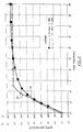
- curve 70 indicates the water temperature with respect to time for a 3.8 l/min (one GPM) flow through tap 43 while curve 70' indicates the temperature per time for a 7.6 l/min (2 GPM) flow.
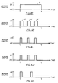
- Figures 4 A-E there is shown the output capacity of a burner from a first time (T1) at which demand was initiated and a second time (T2) at which time demand was terminated.
- Figure 4A shows a burner at 100 % capacity, Q, from initiation time to termination time, without modulation.
- Figure 4C there is shown a burner at 25% capacity using pulse width capacity modulation of the present invention. Accordingly, the pulse period is maintained constant while the "on" pulse of the burner is modulated to vary the capacity.
- the microcomputer system 80 provides another control signal by way of the ribbon cable 89 to the appropriate switching device on the system interface board 82 to supply power from the power supply 83 through the system interface board 82 to the ignition device 40.
- the microcomputer system determines the domestic hot water demand as a function of the temperature of the closed loop liquid leaving the module 12 and adjusts the pulse period of the infrared burner so that the domestic hot water is maintained at a desired temperature. Moreover, if the demand at the tap 43 is decreased then the on-pulse may decrease from that shown in Figure 4B to that shown in Figure 4C.
- flow sensor 66 could be located in line 62 or 64.
Description
- This invention relates generally to a method of controlling the capacity of an integrated heating system and to an integrated heating system for space heating and domestic hot water heating and concerns more particularly a capacity control system for an infrared burner module of an integrated space heating and hot water heating system.
- In heating systems for homes and commercial buildings, central furnaces to heat a space all operate on the same general principle. Air for a space to be heated circulates through a closed system generally comprising sheet metal ductwork, and is heated either as it passes through a heat exchanger in contact with a burning fuel, or as it passes in contact with a secondary fluid which has been heated by a burning fuel. Since burning the fuel results in the production of noxious combustion gases having exhaust temperatures which can exceed 260°C (500°F), it is necessary to exhaust the combustion gases through a chimney or flue to the atmosphere. These systems are relatively inefficient as evidenced by the high exhaust temperatures of the flue gases, and costly due to the construction of the necessary flue or chimney.
- Indirect fired furnaces, ones in which the air being heated is not contacted directly by the combustion gases generated, are generally used in both forced air systems and hydronic systems.
- A forced air system consists primarily of a heat exchanger having combustion chambers arranged in relation to the flow of air to be heated such that fuel is introduced at one end of a chamber where a flame causes heat to be generated. The heat passes through a series of internal baffles before exiting through the other end of the combustion chamber into the flue or chimney. Simultaneously, circulated space air passes around the outside of the heat exchangers to absorb heat through conduction and convection.
- A hydronic system consists primarily of a firebox having a heat exchanger therein. The heat exchanger is in a closed loop for continuously circulating water, a water glycol solution or other suitable heat exchange medium from the heat exchanger to a remote radiator in the space to be heated. However, this system is also relatively inefficient and expensive due to the combustion gas temperatures at the outlet of the firebox and the cost of the chimney.
- Thus, the inefficient home heating system is generally the largest consumer of energy with the domestic hot water system being the second largest consumer of energy. In supplying domestic hot water for homes and commercial buildings, potable hot water systems with ordinary glass-lined, hot water storage tanks are generally used. It is common for these systems to have an enclosed water tank in which are spiraled coils of tubing through which flows the water to be heated. At the lowermost portion of the tank there is normally a burner whose heat is allowed to pass over the coils, thereby heating the water in the tank for use within the home or building. Again, as in the space heating systems for homes and buildings, the heat which is not transferred to the heat exchanger during demand "on-time" and also during standby "off-time", is exhausted at the top of the tank into a flue or chimney to the atmosphere as well as being lost through the tank jacket. Thus, a domestic hot water system is also inefficient because a great portion of the heat is lost directly up the chimney to the atmosphere.
- Because of the rising costs of energy, the incentives to conserve energy are increasing. Consequently, there is currently considerable interest in recovering energy, such as waste heat from combustion heaters which is usually injected into the atmosphere without recovery.
- In an attempt to reclaim reject heat, heat exchanger coils have been installed in the flue of a furnace to transfer some of the waste heat to domestic hot water heaters, thus recovering some usually wasted heat.
- However, a drawback to conserving energy by reclaiming reject heat from a furnace for use by domestic hot water heaters is that both systems are controlled independently, and the energy saved is limited by the temperature of the water in the hot water tank for potable use and typically maintained between 49° C (120 ° F) and 71° C (160° F), the average being at or above the flue gas condensing temperature therefore limiting the efficiency of recovery at or up to a maximum threshold of the product of 88 % to 90 %. The necessity for dual control schemes for semi-integrated furnaces and hot water heaters is due to the blue flame burners used by both systems. In semi-integrated appliances dual controls are necessary because there is not true integration of a common heating loop that provides capacity at different required temperatures for both heating and hot water. This requires a rapid on-off response with modulation of input and flow controls and blue-frame burners by nature are not capable of controlling modulation this way effectively and therefore are limited to operation at some fraction of full input during continuous operation. Capacity of these burners cannot be reduced as demand for hot water is reduced but are fired at full capacity under all operating conditions.
- An integrated heating system according to the precharacterizing portion of
independent method claim 1 orindependent apparatus claim 2 is disclosed in GB-A-2 160 967. In the known heating unit the space heating coil and the domestic water heating coil are connected in parallel. The domestic water heating coil heats the domestic water contained in a tank. - Reference is also made to JP-A-60 82 716 and JP-A-60 117 046 both of which disclosing intermittently feeding fuel gas to a blue flame burner so that the gas is intermittently burnt.
- The object of the invention is to provide a method for efficiently controlling the capacity of an integrated heating system having a radiant burner, and an integrated heating system having a liquid-backed gas-fired heating module with a radiant burner which will control the heat output of the burner to match the rate at which energy is required for either space heating or domestic water heating, or both.
- According to the invention, to achieve this, there is provided a method of controlling the capacity of an integrated heating system for space heating and domestic hot water heating, comprising the steps of using an infrared burner for supplying heat directly to a primary heating fluid loop having a space heating coil therein, and transferring heat from said primary heating fluid loop to a secondary domestic hot water loop, characterized by providing a tankless heat exchange relation between said primary and secondary loops, sensing the presence of domestic hot water flow in the secondary domestic hot water loop, sensing the temperature of the fluid in the primary heating fluid loop; and controlling a pulse width of an "on" pulse of a constant pulse period of said burner to maintain the temperature of the fluid in said primary heating fluid loop within desired limits in response to the sensed domestic hot water flow and the temperature of the fluid in the primary heating fluid loop.
- In further accordance with the invention, there is provided an integrated heating system for space heating and domestic hot water heating having an infrared burner, a coil for receiving heat from the burner, a primary heating fluid loop connected to the coil and having a first heat exchanger for transferring heat to a space and a second heat exchanger for transferring heat from the primary heating fluid loop to a secondary domestic hot water loop, characterized in that the coil for receiving heat from the burner, the first heat exchanger and the second heat exchanger are serially connected in the primary heating fluid loop, that the second heat exchanger is a tankless tube-in-tube heat exchanger, and that there is provided a capacity control system for said burner, said capacity control system having a burner flame control system for controlling the pulsing of repeated ignition and combustion termination of the burner, said burner flame control system including a flow switch for detecting absolute fluid flow in the secondary domestic hot water loop and providing a first signal to a microcomputer means indicative of presence of hot water flow in the secondary domestic hot water loop, and a temperature sensor means for detecting the temperature of the fluid in the primary heating fluid loop at an outlet of the coil receiving heat from the burner and providing a second signal to the microcomputer means indicative of the temperature of the fluid in the primary heating fluid loop whereby said microcomputer provides an output signal to control the pulsing of said repeated ignition and combustion termination of the burner so that the fluid in the primary heating fluid loop is maintained at a desired temperature.
- Accordingly, the object of the invention is attained by providing a capacity modulated control for a heating system for heating a space in a building and domestic hot water. The heating system having a liquid-backed heating module with a quick response and a tankless domestic hot water system, permits maximum radiant heat transfer capacity to be reached quickly, thus allowing pulsing of the burner to maintain heating module liquid temperatures within desired limits.
- For a better understanding of the invention, its operation and specific advantages attained by its use, reference should be had to the accompanying drawings and descriptive matter in which there is illustrated and described a preferred embodiment of the invention.
- In the accompanying drawings forming a part of the specification, and in which reference numerals shown in the drawings designate like or corresponding parts throughout the same,
- Figure 1 is a schematic diagram of an integrated space heating and hot water system embodying the control of the present invention;
- Figure 2 is a graph of the transient domestic hot water temperature response to a call for domestic hot water in an integrated space heating and domestic hot water system;
- Figure 3 is a graph of the percentage output capacity versus the percentage of the on time of the pulse period of an integrated space heating and hot water system embodying the control of the present invention; and
- Figure 4 A-E is a comparison of full capacity control with the pulsed control of the present invention.
- Referring now to Figure 1 there may be seen a schematic view of
residential heating system 10 using a liquid-backedheating module 12 for supplying energy to a primary or series heating fluid loop including a tube-in-tube heat exchanger 50 and afan coil 14 forming a further heat exchanger for transferring heat to a space. The fluid loop further includes aliquid pump 16 for circulating fluid therethrough and anexpansion tank 28 to provide for the volume increase of the heated fluid and for dampening any pressure surges in the fluid loop. The fluid loop arrangement consists ofdischarge pipe 52 which extracts hot fluid fromheating module 12 on demand. The heated fluid flows through the tube-in-tube heat exchanger 50 of conventional construction. The fluid then flows throughpipe 54 and through a three-way diverting valve 56. In a first position the three-way valve 56 allows the fluid to flow directly to theliquid pump 16 throughpipe 55 and back to theheating module 12 throughpipe 57. In a second position the three-way valve 56 allows the fluid in the loop to flow throughpipe 58 intofan coil 14 and throughpipe 59 back to the suction side ofliquid pump 16. - Further, as shown, the secondary domestic hot water loop includes cold
water inlet pipe 62 connected to the inlet of tube-in-tube heat exchanger 50 andoutlet pipe 64 which discharges hot domestic water to tap 43 after passing throughflow switch 66. Amixing valve 60 connectspipe 64 tobypass pipe 65.Mixing valve 60 is preferably a temperature responsive valve which mixes the hot water flowing through theheat exchanger 50 and the cold water flowing through thebypass pipe 65 to ensure that the hot water flowing from thetap 43 is at a desired set temperature. - As further illustrated, the
heating module 12 includes agas line 30 having aregulator 32 for supplying fuel to the module. Further, air is supplied to the module throughline 34. The air/fuel mixture is ignited and burned on theinfrared burner 18 located centrally withinhousing 20. The air/fuel is 100% premixed, thus, no secondary combustion occurs. The heat exchange means 17 is located in spaced relation to theinfrared burner 18 to receive heat from the infrared burner. The heat exchange means is generally in the form of a helical coil and has the fluid flowing therethrough which absorbs heat from the infrared burner, which in turn transfers this heat to the domestic hot water and the space to be heated. - Further, Figure 1 illustrates the integrated domestic hot water/space heating system having a control system in accordance with the principles of the present invention. This control system comprises a
microcomputer system 80, asystem interface board 82, and apower supply 83. Themicrocomputer system 80 may be any device, or combination of devices, suitable for receiving input signals, for processing the received input signals according to preprogrammed procedures, and for generating control signals in response to the processed input signals. The control signals generated by themicrocomputer system 80 are supplied to control devices which control operation of the integrated heating system in response to control signals provided to the control devices from themicrocomputer system 80. - As shown in Figure 1, the
system interface board 82 is connected byribbon cable 89 to themicrocomputer system 80. Thesystem interface board 82 includes switching devices for controlling electrical power flow from themain power supply 83 to three-way valve 56,liquid pump 16, inducer blower (not shown),gas valve 32, andignition device 40. Preferably, the switching devices are electronic components, such as relays, which are controlled in response to control signals from themicrocomputer system 80 which are supplied through theribbon cable 89 to the electronic components on thesystem interface board 82. - The control system determines when to operate the integrated heating system to satisfy the need for space heat and/or domestic hot water. For the purpose of this disclosure "pulsing" shall mean turning the infrared burner on and off repeatedly while the inducer fan runs continuously during the pulse period. Further, "pulse period" shall mean the sum of one "on" and one "off" pulse. The
infrared burner 18 of themodule 12 has the unique feature that it has a-quick response time which allows the maximum radiant heat transfer capacity to be reached quickly, e.g. in about one second, thus transferring its entire output energy to the liquid loop in a short period. More specifically, the temperature of the space to be heated is sensed by athermostat 85 and a signal indicative of this temperature is provided by way of electrical line 91 to themicrocomputer system 80. Further, the flow of domestic hot water flowing throughtap 43 is sensed byflow switch 66 and a signal indicative of this flow is provided by way ofelectrical line 29 to themicrocomputer system 80. Still further, the temperature of the series fluid loop is sensed bytemperature sensor 68 at the outlet of the heat exchange means 17 and a signal indicative of this temperature is provided by way of anelectrical line 26 to themicrocomputer system 80. - Turning now to Figures 2 and 3, there is exemplified the quick response time which allows continuous use of domestic hot water and the output capacity of the infrared burner as a percentage of "on" time.
- In Figure 2,
curve 70 indicates the water temperature with respect to time for a 3.8 l/min (one GPM) flow throughtap 43 while curve 70' indicates the temperature per time for a 7.6 l/min (2 GPM) flow. - In Figure 3, the output capacity of the
infrared burner 18 is shown as a percentage of the burner on time. - Turning now to Figures 4 A-E, there is shown the output capacity of a burner from a first time (T₁) at which demand was initiated and a second time (T₂) at which time demand was terminated. Thus, Figure 4A shows a burner at 100 % capacity, Q, from initiation time to termination time, without modulation. Specifically, Figure 4B shows a 50 % capacity, 0.5Q, made up of three normally equal capacities Q', Q'' and Q''' where


- Each time it is desired to energize the heating module, for example, when the
flow sensor 66 detects flow throughtap 43, themicrocomputer system 80 provides another control signal by way of theribbon cable 89 to the appropriate switching device on thesystem interface board 82 to supply power from thepower supply 83 through thesystem interface board 82 to theignition device 40. The microcomputer system determines the domestic hot water demand as a function of the temperature of the closed loop liquid leaving themodule 12 and adjusts the pulse period of the infrared burner so that the domestic hot water is maintained at a desired temperature. Moreover, if the demand at thetap 43 is decreased then the on-pulse may decrease from that shown in Figure 4B to that shown in Figure 4C. - While the preferred embodiment of the present invention has been depicted and described, it will be appreciated by those skilled in the art that many modifications, substitutions, and changes may be made thereto without departing from the scope of the claims. For example, flow
sensor 66 could be located inline
Claims (3)
- Method of controlling the capacity of an integrated heating system for space heating and domestic hot water heating, comprising the steps of:
using an infrared burner (18) for supplying heat directly to a primary heating fluid loop (52-59) having a space heating coil (14) therein, and
transferring heat from said primary heating fluid loop to a secondary domestic hot water loop, (62,64,43)
characterized by:
providing a tankless heat exchange relation (50) between said primary and secondary loops,
sensing (66) the presence of domestic hot water flow in the secondary domestic hot water loop,
sensing (68) the temperature of the fluid in the primary heating fluid loop; and
controlling a pulse width of an "on" pulse of a constant pulse period of said burner (18) to maintain the temperature of the fluid in said primary heating fluid loop within desired limits in response to the sensed domestic hot water flow and the temperature of the fluid in the primary heating fluid loop. - Integrated heating system for space heating and domestic hot water heating having an infrared burner (18), a coil (17) for receiving heat from the burner (18), a primary heating fluid loop (52-57) connected to the coil (17) and having a first heat exchanger (14) for transferring heat to a space and a second heat exchanger (50) for transferring heat from the primary heating fluid loop to a secondary domestic hot water loop (62,64,43),
characterized in that the coil (17) for receiving heat from the burner (18), the first heat exchanger (14) and the second heat exchanger (50) are serially connected in the primary heating fluid loop (52-57), that the second heat exchanger (50) is a tankless tube-in-tube heat exchanger (50), and that there is provided a capacity control system for said burner (18), said capacity control system having a burner flame control system for controlling the pulsing of repeated ignition and combustion termination of the burner (18), said burner flame control system including a flow switch (66) for detecting absolute fluid flow in the secondary domestic hot water loop and providing a first signal to a microcomputer means (80) indicative of presence of hot water flow in the secondary domestic hot water loop, and a temperature sensor means (68) for detecting the temperature of the fluid in the primary heating fluid loop at an outlet of the coil (17) receiving heat from the burner (18) and providing a second signal to the microcomputer means (80) indicative of the temperature of the fluid in the primary heating fluid loop whereby said microcomputer provides an output signal responsive to said first and second signals to control the pulsing of said repeated ignition and combustion termination of the burner (18) so that the fluid in the primary heating fluid loop is maintained at a desired temperature. - Integrated heating system according to claim 2, characterized in that the secondary domestic hot water loop further includes a thermal mixing valve (60) provided to control the domestic hot water temperature at the desired temperature and that said flow switch (66) is located between the outlet of the tube-in-tube heat exchanger (50) and a hot water tap (43) in the secondary domestic hot water loop.
Applications Claiming Priority (2)
| Application Number | Priority Date | Filing Date | Title |
|---|---|---|---|
| US1730287A | 1987-02-20 | 1987-02-20 | |
| US17302 | 1987-02-20 |
Publications (2)
| Publication Number | Publication Date |
|---|---|
| EP0279768A1 EP0279768A1 (en) | 1988-08-24 |
| EP0279768B1 true EP0279768B1 (en) | 1993-12-08 |
Family
ID=21781849
Family Applications (1)
| Application Number | Title | Priority Date | Filing Date |
|---|---|---|---|
| EP88630024A Expired - Lifetime EP0279768B1 (en) | 1987-02-20 | 1988-02-08 | Capacity control for integrated furnace |
Country Status (5)
| Country | Link |
|---|---|
| EP (1) | EP0279768B1 (en) |
| JP (1) | JPS63210559A (en) |
| CA (1) | CA1286388C (en) |
| DE (1) | DE3886065T2 (en) |
| ES (1) | ES2063059T3 (en) |
Citations (2)
| Publication number | Priority date | Publication date | Assignee | Title |
|---|---|---|---|---|
| GB2160967A (en) * | 1984-06-28 | 1986-01-02 | Thermocatalytic Corp | Gas-fired space heating unit |
| EP0222972A2 (en) * | 1985-07-15 | 1987-05-27 | Toto Ltd. | A multiple-purpose instantaneous gas water heater |
Family Cites Families (2)
| Publication number | Priority date | Publication date | Assignee | Title |
|---|---|---|---|---|
| FR1497608A (en) * | 1966-08-31 | 1967-10-13 | Method of regulating the flow rate of a fluid and a device for carrying out the method | |
| JPS56146948A (en) * | 1980-04-14 | 1981-11-14 | Kubota Ltd | Instantaneous hot water supply unit |
-
1988
- 1988-01-25 CA CA000557264A patent/CA1286388C/en not_active Expired - Lifetime
- 1988-02-08 ES ES88630024T patent/ES2063059T3/en not_active Expired - Lifetime
- 1988-02-08 EP EP88630024A patent/EP0279768B1/en not_active Expired - Lifetime
- 1988-02-08 DE DE19883886065 patent/DE3886065T2/en not_active Expired - Fee Related
- 1988-02-17 JP JP3494688A patent/JPS63210559A/en active Pending
Patent Citations (2)
| Publication number | Priority date | Publication date | Assignee | Title |
|---|---|---|---|---|
| GB2160967A (en) * | 1984-06-28 | 1986-01-02 | Thermocatalytic Corp | Gas-fired space heating unit |
| EP0222972A2 (en) * | 1985-07-15 | 1987-05-27 | Toto Ltd. | A multiple-purpose instantaneous gas water heater |
Also Published As
| Publication number | Publication date |
|---|---|
| JPS63210559A (en) | 1988-09-01 |
| CA1286388C (en) | 1991-07-16 |
| ES2063059T3 (en) | 1995-01-01 |
| EP0279768A1 (en) | 1988-08-24 |
| DE3886065D1 (en) | 1994-01-20 |
| DE3886065T2 (en) | 1994-04-07 |
Similar Documents
| Publication | Publication Date | Title |
|---|---|---|
| EP0279767B1 (en) | Integral liquid-backed gas-fired space heating and hot water system | |
| US5076494A (en) | Integrated hot water supply and space heating system | |
| EP3418649B1 (en) | Hot water appliance and hot water system using the same | |
| US4350144A (en) | Hot water heating system | |
| US4251028A (en) | Energy recovery system for boiler and domestic water | |
| US4880157A (en) | Capacity control for integrated furnace | |
| US5881952A (en) | Heater for liquids | |
| US4106692A (en) | Heating system with reserve thermal storage capacity | |
| US4122999A (en) | Forced air heating system | |
| EP0279768B1 (en) | Capacity control for integrated furnace | |
| US2540055A (en) | Heating system | |
| US6672255B1 (en) | Flue gas energy transfer system | |
| KR0148211B1 (en) | Hot water auto distrirutor of a boiler | |
| EP0635683B1 (en) | High-efficiency combined boiler | |
| EP0146264B1 (en) | Control of a central heating system | |
| US4487361A (en) | Heat exchanger flame control | |
| KR100212512B1 (en) | Heating control method for large volume gas boiler | |
| EP1135653B1 (en) | Apparatus for regulating heater cycles to improve forced-air heating system efficiency | |
| KR100422867B1 (en) | Optimization Method For Tapping Temperature Of Initial Hot-Water In Condensing Boiler | |
| JP3172014B2 (en) | Solar water heater compatible type water heater | |
| JPH0960974A (en) | Heat exchanger for hot water supply device | |
| EP0445889B1 (en) | Combined central-heating and water-heating boiler | |
| GB2286654A (en) | Apparatus for providing hot water and/or central heating | |
| JPH08219549A (en) | Multi-can installation type hot water supply system of gas boiling warm water boiler | |
| KR0126592Y1 (en) | Apparatus of hot water for a gas boiler |
Legal Events
| Date | Code | Title | Description |
|---|---|---|---|
| PUAI | Public reference made under article 153(3) epc to a published international application that has entered the european phase |
Free format text: ORIGINAL CODE: 0009012 |
|
| AK | Designated contracting states |
Kind code of ref document: A1 Designated state(s): DE ES FR GB IT |
|
| 17P | Request for examination filed |
Effective date: 19890117 |
|
| 17Q | First examination report despatched |
Effective date: 19910115 |
|
| GRAA | (expected) grant |
Free format text: ORIGINAL CODE: 0009210 |
|
| AK | Designated contracting states |
Kind code of ref document: B1 Designated state(s): DE ES FR GB IT |
|
| ET | Fr: translation filed | ||
| REF | Corresponds to: |
Ref document number: 3886065 Country of ref document: DE Date of ref document: 19940120 |
|
| ITF | It: translation for a ep patent filed |
Owner name: UFFICIO BREVETTI RICCARDI & C. |
|
| PLBE | No opposition filed within time limit |
Free format text: ORIGINAL CODE: 0009261 |
|
| STAA | Information on the status of an ep patent application or granted ep patent |
Free format text: STATUS: NO OPPOSITION FILED WITHIN TIME LIMIT |
|
| 26N | No opposition filed | ||
| REG | Reference to a national code |
Ref country code: ES Ref legal event code: FG2A Ref document number: 2063059 Country of ref document: ES Kind code of ref document: T3 |
|
| PGFP | Annual fee paid to national office [announced via postgrant information from national office to epo] |
Ref country code: FR Payment date: 19950113 Year of fee payment: 8 |
|
| PGFP | Annual fee paid to national office [announced via postgrant information from national office to epo] |
Ref country code: GB Payment date: 19950119 Year of fee payment: 8 Ref country code: DE Payment date: 19950119 Year of fee payment: 8 |
|
| PGFP | Annual fee paid to national office [announced via postgrant information from national office to epo] |
Ref country code: ES Payment date: 19950208 Year of fee payment: 8 |
|
| PG25 | Lapsed in a contracting state [announced via postgrant information from national office to epo] |
Ref country code: GB Effective date: 19960208 |
|
| PG25 | Lapsed in a contracting state [announced via postgrant information from national office to epo] |
Ref country code: ES Free format text: LAPSE BECAUSE OF NON-PAYMENT OF DUE FEES Effective date: 19960209 |
|
| GBPC | Gb: european patent ceased through non-payment of renewal fee |
Effective date: 19960208 |
|
| PG25 | Lapsed in a contracting state [announced via postgrant information from national office to epo] |
Ref country code: FR Effective date: 19961031 |
|
| PG25 | Lapsed in a contracting state [announced via postgrant information from national office to epo] |
Ref country code: DE Effective date: 19961101 |
|
| REG | Reference to a national code |
Ref country code: FR Ref legal event code: ST |
|
| REG | Reference to a national code |
Ref country code: ES Ref legal event code: FD2A Effective date: 19990301 |
|
| PG25 | Lapsed in a contracting state [announced via postgrant information from national office to epo] |
Ref country code: IT Free format text: LAPSE BECAUSE OF NON-PAYMENT OF DUE FEES;WARNING: LAPSES OF ITALIAN PATENTS WITH EFFECTIVE DATE BEFORE 2007 MAY HAVE OCCURRED AT ANY TIME BEFORE 2007. THE CORRECT EFFECTIVE DATE MAY BE DIFFERENT FROM THE ONE RECORDED. Effective date: 20050208 |