EP0279674B1 - Cooling system for glass molding equipment - Google Patents
Cooling system for glass molding equipment Download PDFInfo
- Publication number
- EP0279674B1 EP0279674B1 EP88301374A EP88301374A EP0279674B1 EP 0279674 B1 EP0279674 B1 EP 0279674B1 EP 88301374 A EP88301374 A EP 88301374A EP 88301374 A EP88301374 A EP 88301374A EP 0279674 B1 EP0279674 B1 EP 0279674B1
- Authority
- EP
- European Patent Office
- Prior art keywords
- cooling
- glass
- forming
- insert
- cooling insert
- Prior art date
- Legal status (The legal status is an assumption and is not a legal conclusion. Google has not performed a legal analysis and makes no representation as to the accuracy of the status listed.)
- Expired - Lifetime
Links
- 238000001816 cooling Methods 0.000 title claims description 82
- 239000011521 glass Substances 0.000 title claims description 37
- 238000000465 moulding Methods 0.000 title claims description 23
- 238000004519 manufacturing process Methods 0.000 claims description 23
- 239000012809 cooling fluid Substances 0.000 claims description 10
- 239000000956 alloy Substances 0.000 claims description 8
- 239000000463 material Substances 0.000 claims description 7
- 229910000743 fusible alloy Inorganic materials 0.000 claims description 6
- 238000000034 method Methods 0.000 claims description 6
- 229910052782 aluminium Inorganic materials 0.000 claims description 3
- XAGFODPZIPBFFR-UHFFFAOYSA-N aluminium Chemical compound [Al] XAGFODPZIPBFFR-UHFFFAOYSA-N 0.000 claims description 3
- 239000012530 fluid Substances 0.000 claims description 3
- 239000010935 stainless steel Substances 0.000 claims description 2
- 229910001220 stainless steel Inorganic materials 0.000 claims description 2
- 239000007769 metal material Substances 0.000 claims 4
- 238000002844 melting Methods 0.000 claims 3
- 230000008018 melting Effects 0.000 claims 3
- 238000007496 glass forming Methods 0.000 claims 2
- 230000001419 dependent effect Effects 0.000 claims 1
- 238000007599 discharging Methods 0.000 claims 1
- 229910001092 metal group alloy Inorganic materials 0.000 claims 1
- 239000007787 solid Substances 0.000 claims 1
- 238000009736 wetting Methods 0.000 claims 1
- 238000003825 pressing Methods 0.000 description 7
- 229910000679 solder Inorganic materials 0.000 description 5
- 229910045601 alloy Inorganic materials 0.000 description 4
- 239000002826 coolant Substances 0.000 description 4
- 229910052751 metal Inorganic materials 0.000 description 3
- 239000002184 metal Substances 0.000 description 3
- 239000006060 molten glass Substances 0.000 description 3
- 238000005336 cracking Methods 0.000 description 2
- 238000009826 distribution Methods 0.000 description 2
- 239000007788 liquid Substances 0.000 description 2
- XLYOFNOQVPJJNP-UHFFFAOYSA-N water Substances O XLYOFNOQVPJJNP-UHFFFAOYSA-N 0.000 description 2
- 230000004888 barrier function Effects 0.000 description 1
- 229910052797 bismuth Inorganic materials 0.000 description 1
- JCXGWMGPZLAOME-UHFFFAOYSA-N bismuth atom Chemical compound [Bi] JCXGWMGPZLAOME-UHFFFAOYSA-N 0.000 description 1
- 238000009835 boiling Methods 0.000 description 1
- 239000004020 conductor Substances 0.000 description 1
- 239000000498 cooling water Substances 0.000 description 1
- 230000007547 defect Effects 0.000 description 1
- 230000007812 deficiency Effects 0.000 description 1
- 230000000694 effects Effects 0.000 description 1
- 239000000284 extract Substances 0.000 description 1
- 238000000605 extraction Methods 0.000 description 1
- 239000012212 insulator Substances 0.000 description 1
- 150000002739 metals Chemical class 0.000 description 1
- 238000012986 modification Methods 0.000 description 1
- 230000004048 modification Effects 0.000 description 1
- 230000003287 optical effect Effects 0.000 description 1
- 238000007789 sealing Methods 0.000 description 1
- 238000005476 soldering Methods 0.000 description 1
- 125000006850 spacer group Chemical group 0.000 description 1
- 230000001502 supplementing effect Effects 0.000 description 1
- 239000002470 thermal conductor Substances 0.000 description 1
Images
Classifications
-
- C—CHEMISTRY; METALLURGY
- C03—GLASS; MINERAL OR SLAG WOOL
- C03B—MANUFACTURE, SHAPING, OR SUPPLEMENTARY PROCESSES
- C03B11/00—Pressing molten glass or performed glass reheated to equivalent low viscosity without blowing
- C03B11/12—Cooling, heating, or insulating the plunger, the mould, or the glass-pressing machine; cooling or heating of the glass in the mould
-
- C—CHEMISTRY; METALLURGY
- C03—GLASS; MINERAL OR SLAG WOOL
- C03B—MANUFACTURE, SHAPING, OR SUPPLEMENTARY PROCESSES
- C03B11/00—Pressing molten glass or performed glass reheated to equivalent low viscosity without blowing
- C03B11/12—Cooling, heating, or insulating the plunger, the mould, or the glass-pressing machine; cooling or heating of the glass in the mould
- C03B11/125—Cooling
- C03B11/127—Cooling of hollow or semi-hollow articles or their moulds
Definitions
- This invention relates to a glass molding assembly and a method of colling glass molding equipment. More specifically, the invention relates to a cooling system for use in molds, plungers and even mold rings utilized in the press-forming of glass into articles.
- the rapid and controlled exchange of heat between the glass and the mold equipment is extremely important. It is particularly important that the temperature of the mold equipment be kept within a range that is most advantageous for the pressing process. Such temperature range is limited by operational constraints, in that the range should not exceed the temperature at which the glass begins to stick or adhere to the mold equipment, nor should such range be less than the temperature at which optical defects or checks are produced in the product.
- the temperature range limitation materially restricts the range of production speeds which conventional mold equipment may operate, since the known cooling systems forming a part thereof are engineered for a particular predetermined production speed, and thus to be operable, such equipment had to be utilized within a limited operating speed range of about 2-3% of the normally available speed range of a production run.
- a castable core metal was provided within the thermally determinate hollow plunger body, which could be varied to vary the thermal conductivity of such hollow body.
- Versatility was materially limited in view of the fact that thermal insulators and conductors forming a part thereof predetermined the heat removal adjacent various areas, which could not be varied when production rates were changed.
- the cooling system of the present invention has been developed, and accordingly, it is an object of the present invention to provide a method of and apparatus for cooling glass molding equipment which is independent of the mechanical considerations for forming the molding part. In addition, it is an object of the present invention to provide a cooling system which has the capability of accommodating a wide range of production speeds of up to preferably about 1000% while utilizing the same molding equipment.
- the glass molding assembly of the present invention is defined in Claim 1, and the method of the invention is defined in Claim 8.
- the present invention uses a new concept in providing cooling for glass molding equipment by uncoupling the mechanical and thermal considerations required for efficient operation.
- a plunger or mold can now be designed with a minimum wall thickness sufficient to withstand mechanical forces and deflection.
- the geometry of the mold or plunger can be very simple with nearly uniform thicknesses across their extent, thus materially simplifying fabrication and minimizing stress concentrations to thereby reduce maximum stresses.
- the separate cooling block removably positionable within a hollow interior of the plunger is designed with the proper shape and thermal conductivity to provide the cooling necessary for a desired production speed.
- a differently designed cooling block would be inserted within the same mold or plunger. Since the cooling block can be made of material which can be easily machined, and since the various molds and plungers may be utilized with different cooling blocks, mold equipment cost can be significantly reduced.
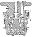
- the Figure is an elevational view in section of a plunger incorporating the cooling system of the present invention.
- a plunger assembly 10 including a plunger body member 11 having a hollow interior or cavity 12 provided with a cooling insert block 14.
- the plunger member 11 is connected to a plunger head 16, such as by bolts 18.
- the plunger 11 has an operating nose portion 20 having an outer glass contacting surface 22 and an inner surface 24, forming a portion of the inner wall of cavity 12.
- the cooling block 14 has a forward portion 26 with an outer surface 28 which is spaced-apart from the inner surface 24 with a predetermined distance, such as by means of an upper shoulder offset (not shown) or a spacer plug 30, so as to form a gap 32 between the forward portion 26 of the cooling insert 14 and the operating nose portion 20 of the plunger 11.
- the gap 32 is provided with a material 34 which is in a molten or liquid state at standard glass pressing temperatures, but which has a relatively high boiling point, such as soldering metals and other low melting alloys.
- an expansion area 36 is provided within the gap 32 above the alloy 34 to accommodate the expansion of the alloy during the glass pressing operations.
- the cooling insert block 14 is provided with an inner hollow portion 38 which may include cooling passages 40.
- a suitable coolant such as water
- An outlet passage 46, formed in the plunger head 16, communicates with the hollow interior portion 38 of the cooling block 14 for facilitating the removal of the cooling fluid from the insert 14 while preventing such fluid from directly contacting plunger 11.
- a suitable sealing ring 48 may be provided between the insert block 14 the plunger member 11 to prevent the coolant from entering the gap 32.
- the cooling insert 14 is shown as a rather massive block with cooling passages 40 supplementing the heat extraction from the plunger in selected areas, it is understood that the cooling insert could also take the form of a rather thin shell-like member, depending upon the particular thermal considerations necessary for the selected forming operation. That is, the thickness of the insert not only depends upon the thermal conductivity of the material utilized, but also the intended production speed. For a given thermal conductivity, at higher production speeds the plunger tends to run hotter due to extended contact with the molten glass, and accordingly a thinner walled shell-like cooling insert would be desirable since it would provide a steeper temperature gradient between the glass contacting surface 22 and the cooling surface of the hollow portion 38, to thereby facilitate faster cooling of the plunger.
- a material having a moderate thermal conductivity such as stainless steel, would be preferred over one having a relatively high thermal conductivity such as aluminum.
- the temperature gradient between the glass contact surface and the hollow cooling portion is reduced, and in order to prevent overcooling of the plunger, a thicker block-like cooling insert is utilized. Accordingly, although the surface of the hollow portion would be close to that of the cooling fluid, the thicker insert block provides a more shallow gradient to facilitate a desired uniform cooling of the plunger without resulting in overcooling.
- a high conductivity material such as aluminum is usually preferred since it facilitates the rate of heat removal in a uniform manner.
- the appropriate thickness of the cooling insert block to be utilized depends upon the desired speed of operation and the thermal conductivity of the cooler insert.
- the gap 32 between the inner surface 24 of the plunger 11 and the outer surface 28 of the insert 14 is preferrably of a minimum uniform thickness for effecting good heat transfer through the molten solder between the plunger and the cooling block. If the gap were not present and no molten alloy were utilized, the heat transfer between the cooling block and the plunger would merely be by a face-to-face metal-to-metal contact, which would provide inconsistent and non-uniform heat transfer between the surfaces. Thus, the utilization of the low melting alloy wets both the outer surface 28 of the cooling block 14 and the back or inner surface 24 of the plunger 11 to insure good heat transfer between such surfaces. By having a uniform gap, a uniform heat transfer is accordingly provided between the insert and the plunger.
- the liquid solder within the gap while functioning to provide good heat transfer between the plunger and the cooling block, does not materially effect the total cooling system.
- the smaller gap reduces the amount of molten solder necessary to provide the heat transfer and accordingly minimizes the amount of expansion and the need for expansion area 36.
- solders or low melting alloys may be utilized which are compatible with the plunger and expansion block, such as an alloy of 55.5% bismuth and 44.5% lead. Such solders may melt anywhere in the range of from about 150°F to about 250°F.
- the mechanical design of the plunger and the thermal design of the cooling insert block can be uncoupled so that various insert blocks may be utilized with the same plunger, depending upon the desired production speeds to be utilized. That is, in the conventional plungers of the prior art, the plunger design and the internal water cooling where intimately connected, with the plunger thickness at various portions being determined by the speed of production and the temperature distribution on the face of the plunger. When the production speed was changed, there was little that could be done to compensate for the different heat input to the plunger, and accordingly either sticking occurred when higher production speeds were utilized, or checks and cracking occurred when lower production speeds were utilized.
- the desired temperature profile to be produced at the plunger face can be controlled with different cooler inserts having desired geometries to produce the correct temperature profile.
- the plunger can now be designed with minimum uniform thicknesses to merely withstand mechanical forces and deflection.
- the cooling block may be easily machined and designed in proper shape to provide the cooling to the plunger. Accordingly, since the cooling block can be reused with different plungers, mold equipment costs can be significantly reduced.
- the invention has been disclosed with particular reference to a plunger, the invention is equally applicable to cooling systems for molds, mold rings and the like.
Landscapes
- Engineering & Computer Science (AREA)
- Chemical & Material Sciences (AREA)
- Manufacturing & Machinery (AREA)
- Materials Engineering (AREA)
- Organic Chemistry (AREA)
- Moulds For Moulding Plastics Or The Like (AREA)
- Joining Of Glass To Other Materials (AREA)
- Re-Forming, After-Treatment, Cutting And Transporting Of Glass Products (AREA)
Description
- This invention relates to a glass molding assembly and a method of colling glass molding equipment. More specifically, the invention relates to a cooling system for use in molds, plungers and even mold rings utilized in the press-forming of glass into articles.
- In the pressing of glass articles from molten or semi-molten glass, the rapid and controlled exchange of heat between the glass and the mold equipment is extremely important. It is particularly important that the temperature of the mold equipment be kept within a range that is most advantageous for the pressing process. Such temperature range is limited by operational constraints, in that the range should not exceed the temperature at which the glass begins to stick or adhere to the mold equipment, nor should such range be less than the temperature at which optical defects or checks are produced in the product. The temperature range limitation materially restricts the range of production speeds which conventional mold equipment may operate, since the known cooling systems forming a part thereof are engineered for a particular predetermined production speed, and thus to be operable, such equipment had to be utilized within a limited operating speed range of about 2-3% of the normally available speed range of a production run.
- The problem of maintaining the mold equipment within a limited temperature range during various production speeds is aggravated by differential rates of heat removal from the mold equipment depending upon the geometry of the article being formed. In the pressing of glass, the rate of heat removal from the molten glass by the mold equipment depends to a large extent on the glass thickness and its geometric shape in localized regions. If the glass article to be produced has regions of both broad flat or slightly curved surfaces and also regions of relatively sharp corners, the rate of heat exchange between the glass and the mold equipment can differ significantly between such regions. Accordingly, the cooling systems of the prior art were designed specifically, not only for predetermined production speeds, but also for the differential heat removal necessary adjacent the various areas at such predetermined production speed. Thus, in such conventional mold equipment both the thermal and the mechanical considerations of the equipment had to be incorporated into the design. In other words, the mechanical and thermal considerations were by necessity coupled together, which further limited the versatility of such equipment.
- Examples of the coupled cooling systems of the prior art are set forth in U.S. Patents Nos. 3,202,498; 3,258,324; and 4,094,657. Both the '498 and '657 patents are concerned with the problems encountered in uniformly removing heat during the pressing of glass articles having substantial variations in geometric shape and thickness. That is, specific cooling systems had to be designed for each plunger which included specifically positioned cooling jets and/or cooling grooves and insulated portions formed within the body of the plunger per se. Thus, both the mechanical and the thermal design considerations of such plungers were integrally coupled together. The '324 patent also incorporated specially designed jets within a cooling system and thermal conductors and thermal barriers formed within a sealed hollow plunger body. In addition, a castable core metal was provided within the thermally determinate hollow plunger body, which could be varied to vary the thermal conductivity of such hollow body. Versatility, however, was materially limited in view of the fact that thermal insulators and conductors forming a part thereof predetermined the heat removal adjacent various areas, which could not be varied when production rates were changed.
- In order to overcome the above-noted deficiencies in the pressing of glass items, the cooling system of the present invention has been developed, and accordingly, it is an object of the present invention to provide a method of and apparatus for cooling glass molding equipment which is independent of the mechanical considerations for forming the molding part. In addition, it is an object of the present invention to provide a cooling system which has the capability of accommodating a wide range of production speeds of up to preferably about 1000% while utilizing the same molding equipment.
- The glass molding assembly of the present invention is defined in Claim 1, and the method of the invention is defined in Claim 8.
- In its simplest form, the present invention uses a new concept in providing cooling for glass molding equipment by uncoupling the mechanical and thermal considerations required for efficient operation. For example, a plunger or mold can now be designed with a minimum wall thickness sufficient to withstand mechanical forces and deflection. The geometry of the mold or plunger can be very simple with nearly uniform thicknesses across their extent, thus materially simplifying fabrication and minimizing stress concentrations to thereby reduce maximum stresses. To insure the proper thermal performance of the plunger, the separate cooling block removably positionable within a hollow interior of the plunger is designed with the proper shape and thermal conductivity to provide the cooling necessary for a desired production speed. However, should different production speeds be encountered, a differently designed cooling block would be inserted within the same mold or plunger. Since the cooling block can be made of material which can be easily machined, and since the various molds and plungers may be utilized with different cooling blocks, mold equipment cost can be significantly reduced.
- The Figure is an elevational view in section of a plunger incorporating the cooling system of the present invention.
- Although the cooling system of the present invention may be utilized with virtually any glass molding equipment including plungers, molds and mold rings, for the sake of simplicity, the invention will be described in connection with a cooling system utilized with a plunger. Referring now to the drawing, a
plunger assembly 10 is shown including aplunger body member 11 having a hollow interior orcavity 12 provided with acooling insert block 14. Theplunger member 11 is connected to aplunger head 16, such as bybolts 18. Theplunger 11 has anoperating nose portion 20 having an outerglass contacting surface 22 and an inner surface 24, forming a portion of the inner wall ofcavity 12. - The
cooling block 14 has aforward portion 26 with anouter surface 28 which is spaced-apart from the inner surface 24 with a predetermined distance, such as by means of an upper shoulder offset (not shown) or aspacer plug 30, so as to form agap 32 between theforward portion 26 of the cooling insert 14 and theoperating nose portion 20 of theplunger 11. Thegap 32 is provided with amaterial 34 which is in a molten or liquid state at standard glass pressing temperatures, but which has a relatively high boiling point, such as soldering metals and other low melting alloys. Preferrably, anexpansion area 36 is provided within thegap 32 above thealloy 34 to accommodate the expansion of the alloy during the glass pressing operations. - The
cooling insert block 14 is provided with an innerhollow portion 38 which may includecooling passages 40. A suitable coolant, such as water, is applied to thehollow portion 38 of thecooling block 14 by means of acoolant inlet passage 42, formed in theplunger head 16, and adistributor deflector 44, associated with thehollow portion 38 for distributing the coolant within theinsert 14. Anoutlet passage 46, formed in theplunger head 16, communicates with the hollowinterior portion 38 of thecooling block 14 for facilitating the removal of the cooling fluid from theinsert 14 while preventing such fluid from directly contactingplunger 11. Asuitable sealing ring 48 may be provided between theinsert block 14 theplunger member 11 to prevent the coolant from entering thegap 32. - Although the
cooling insert 14 is shown as a rather massive block withcooling passages 40 supplementing the heat extraction from the plunger in selected areas, it is understood that the cooling insert could also take the form of a rather thin shell-like member, depending upon the particular thermal considerations necessary for the selected forming operation. That is, the thickness of the insert not only depends upon the thermal conductivity of the material utilized, but also the intended production speed. For a given thermal conductivity, at higher production speeds the plunger tends to run hotter due to extended contact with the molten glass, and accordingly a thinner walled shell-like cooling insert would be desirable since it would provide a steeper temperature gradient between theglass contacting surface 22 and the cooling surface of thehollow portion 38, to thereby facilitate faster cooling of the plunger. However, when utilizing a relatively thin walled cooler insert, in order to moderate the severity of the cooling supplied by the cooling water and provide a more uniform cooling distribution, a material having a moderate thermal conductivity such as stainless steel, would be preferred over one having a relatively high thermal conductivity such as aluminum. - In contrast, however, when lower production speeds are utilized, the plunger glass contacting time is materially reduced and accordingly the amount of heat which the plunger extracts from the glass is reduced. Therefore, if the amount of cooling, normally utilized with standard operating production speeds were not minimized, the plunger would become overcooled and result in checks or cracking of the glass articles. Thus, in order to provide a more shallow temperature gradient between the hot glass contacting surface of the plunger and the cooling surface of the hollow portion of the insert, a thicker insert block, such as shown in the figure, is desirable. That is, since less heat is absorbed by the plunger when it is operated at slower production speeds, the temperature gradient between the glass contact surface and the hollow cooling portion is reduced, and in order to prevent overcooling of the plunger, a thicker block-like cooling insert is utilized. Accordingly, although the surface of the hollow portion would be close to that of the cooling fluid, the thicker insert block provides a more shallow gradient to facilitate a desired uniform cooling of the plunger without resulting in overcooling. When utilizing such cooling insert blocks, a high conductivity material such as aluminum is usually preferred since it facilitates the rate of heat removal in a uniform manner. As previously mentioned, the appropriate thickness of the cooling insert block to be utilized depends upon the desired speed of operation and the thermal conductivity of the cooler insert.
- The
gap 32 between the inner surface 24 of theplunger 11 and theouter surface 28 of theinsert 14 is preferrably of a minimum uniform thickness for effecting good heat transfer through the molten solder between the plunger and the cooling block. If the gap were not present and no molten alloy were utilized, the heat transfer between the cooling block and the plunger would merely be by a face-to-face metal-to-metal contact, which would provide inconsistent and non-uniform heat transfer between the surfaces. Thus, the utilization of the low melting alloy wets both theouter surface 28 of thecooling block 14 and the back or inner surface 24 of theplunger 11 to insure good heat transfer between such surfaces. By having a uniform gap, a uniform heat transfer is accordingly provided between the insert and the plunger. Further, by utilizing a small gap, such as not exceeding about one-quarter inch, the liquid solder within the gap, while functioning to provide good heat transfer between the plunger and the cooling block, does not materially effect the total cooling system. In addition, the smaller gap reduces the amount of molten solder necessary to provide the heat transfer and accordingly minimizes the amount of expansion and the need forexpansion area 36. Various solders or low melting alloys may be utilized which are compatible with the plunger and expansion block, such as an alloy of 55.5% bismuth and 44.5% lead. Such solders may melt anywhere in the range of from about 150°F to about 250°F. - It thus can be seen that the mechanical design of the plunger and the thermal design of the cooling insert block can be uncoupled so that various insert blocks may be utilized with the same plunger, depending upon the desired production speeds to be utilized. That is, in the conventional plungers of the prior art, the plunger design and the internal water cooling where intimately connected, with the plunger thickness at various portions being determined by the speed of production and the temperature distribution on the face of the plunger. When the production speed was changed, there was little that could be done to compensate for the different heat input to the plunger, and accordingly either sticking occurred when higher production speeds were utilized, or checks and cracking occurred when lower production speeds were utilized. With the present invention, however, the desired temperature profile to be produced at the plunger face can be controlled with different cooler inserts having desired geometries to produce the correct temperature profile. Further, the plunger can now be designed with minimum uniform thicknesses to merely withstand mechanical forces and deflection. In addition, the cooling block may be easily machined and designed in proper shape to provide the cooling to the plunger. Accordingly, since the cooling block can be reused with different plungers, mold equipment costs can be significantly reduced. As previously mentioned, although the invention has been disclosed with particular reference to a plunger, the invention is equally applicable to cooling systems for molds, mold rings and the like.
- Although we have disclosed the now preferred embodiments of our invention, it will be understood that various changes and modification may be made thereto without departing from the scope of the appended claims.
Claims (9)
a molding body member (11), said body member having a hollow interior cavity (12);
a cooling insert member (14) removably positioned within said hollow interior cavity of said body member, said cooling insert member having a hollow portion (38);
means (42, 44, 46) for supplying cooling fluid to said hollow portion (38) of said cooling insert member;
and
a low melting metal material (34), which is molten at glass forming temperatures, provided in said hollow interior cavity (12) between, and in intimate contact with, said body member (11) and said cooling insert member (14) to provide good thermal conductivity therebetween.
providing a forming member (11) with a hollow interior (12) and a glass contacting surface (22) on one side thereof opposite said hollow interior and an inner surface (24) forming a portion of said hollow interior;
positioning a removable cooling insert (14) within said hollow interior;
spacing a forward surface portion (28) of said cooling insert a predetermined distance from said inner surface (24) and forming a uniform gap (32) between said cooling insert and said forming member;
substantially filling said gap with a low melting alloy material (34) which is molten at standard glass forming temperatures and wetting both said inner surface (24) of said forming member and said forward surface (28) portion of said cooling insert with said molten metal alloy material to facilitate heat transfer between said forming member and said cooling insert;
providing an expansion chamber (36) within said gap for said low melting alloy material;
supplying cooling fluid to the interior of said insert (14) while preventing the direct contact of said cooling fluid with said forming member to remove heat from said forming member by thermal conductivity through said molten alloy material and said cooling insert; and
removing said cooling insert (14) from said forming member and providing additional cooling inserts having various thermal characteristics for effecting a desired heat removal dependent upon the rate of production at which the forming member is utilized.
Applications Claiming Priority (2)
| Application Number | Priority Date | Filing Date | Title |
|---|---|---|---|
| US15993 | 1987-02-18 | ||
| US07/015,993 US4790867A (en) | 1987-02-18 | 1987-02-18 | Cooling system for glass molding equipment |
Publications (2)
| Publication Number | Publication Date |
|---|---|
| EP0279674A1 EP0279674A1 (en) | 1988-08-24 |
| EP0279674B1 true EP0279674B1 (en) | 1992-04-01 |
Family
ID=21774769
Family Applications (1)
| Application Number | Title | Priority Date | Filing Date |
|---|---|---|---|
| EP88301374A Expired - Lifetime EP0279674B1 (en) | 1987-02-18 | 1988-02-18 | Cooling system for glass molding equipment |
Country Status (5)
| Country | Link |
|---|---|
| US (1) | US4790867A (en) |
| EP (1) | EP0279674B1 (en) |
| JP (1) | JPS63222025A (en) |
| KR (1) | KR880009873A (en) |
| DE (1) | DE3869640D1 (en) |
Families Citing this family (5)
| Publication number | Priority date | Publication date | Assignee | Title |
|---|---|---|---|---|
| JPH05155633A (en) * | 1991-12-09 | 1993-06-22 | Shinhoukoku Seitetsu Kk | Vessel forming mold |
| US5632794A (en) * | 1995-05-31 | 1997-05-27 | Corning Incorporated | Method and apparatus for cooling a glass pressing plunger |
| DE10118260A1 (en) * | 2001-04-11 | 2002-10-24 | Schott Glas | Process for deforming bodies made from glass or glass-ceramic comprises placing the body on a mold, and heating using short wave infrared radiation |
| ITCN20120003A1 (en) * | 2012-01-23 | 2013-07-24 | Bruno Viada | PHASE TRANSITION MOLDS FOR CABLE GLASS MANUFACTURING MACHINES |
| CN109574470B (en) * | 2018-12-11 | 2021-05-18 | 重庆兴宝兴玻璃制品有限公司 | Quick cooling and drying equipment for mold |
Family Cites Families (8)
| Publication number | Priority date | Publication date | Assignee | Title |
|---|---|---|---|---|
| US3202498A (en) * | 1961-05-17 | 1965-08-24 | Owens Illinois Glass Co | Glass forming plunger |
| US3171731A (en) * | 1961-07-03 | 1965-03-02 | Glass Container Industry Res C | Cooling system for glass forming machines |
| US3258324A (en) * | 1962-11-21 | 1966-06-28 | Owens Illinois Glass Co | Glass pressing apparatus |
| NL7013364A (en) * | 1970-09-10 | 1972-03-14 | ||
| US3849101A (en) * | 1972-11-06 | 1974-11-19 | Emhart Corp | Cooling system for glass forming mold |
| JPS5347253B2 (en) * | 1974-10-16 | 1978-12-20 | ||
| US4059429A (en) * | 1976-10-04 | 1977-11-22 | Corning Glass Works | Glass pressing plunger cooling |
| US4140512A (en) * | 1978-03-27 | 1979-02-20 | Corning Glass Works | Liquid cooling system for glass forming apparatus |
-
1987
- 1987-02-18 US US07/015,993 patent/US4790867A/en not_active Expired - Fee Related
-
1988
- 1988-02-16 KR KR1019880001619A patent/KR880009873A/en not_active Withdrawn
- 1988-02-18 JP JP63036451A patent/JPS63222025A/en active Pending
- 1988-02-18 DE DE8888301374T patent/DE3869640D1/en not_active Expired - Lifetime
- 1988-02-18 EP EP88301374A patent/EP0279674B1/en not_active Expired - Lifetime
Also Published As
| Publication number | Publication date |
|---|---|
| EP0279674A1 (en) | 1988-08-24 |
| JPS63222025A (en) | 1988-09-14 |
| DE3869640D1 (en) | 1992-05-07 |
| US4790867A (en) | 1988-12-13 |
| KR880009873A (en) | 1988-10-05 |
Similar Documents
| Publication | Publication Date | Title |
|---|---|---|
| US4832254A (en) | Process for the manufacture of an injection mould | |
| AU2005244031B2 (en) | Method and apparatus for coupling melt conduits in a molding system and/or a runner system | |
| US6962492B2 (en) | Gap seal between nozzle components | |
| US5513691A (en) | Mold for continuous casting and method of making the mold | |
| US4790867A (en) | Cooling system for glass molding equipment | |
| CN210334292U (en) | Large-scale thin wall spare die-casting molding system | |
| US3258324A (en) | Glass pressing apparatus | |
| US20060115551A1 (en) | Injection-mold pin | |
| JP2001259821A (en) | Amorphous alloy molded product manufacturing equipment, manufacturing mold and manufacturing method | |
| CA1220608A (en) | Die casting mold | |
| US5832981A (en) | Construction and method of making heat-exchanging cast metal forming tool | |
| GB2109721A (en) | Apparatus for the continuous casting of metals such as copper alloys | |
| US7082985B2 (en) | Moulding apparatus | |
| JPH0255642A (en) | Method and device for continuously casting strip steel | |
| EP0745563B1 (en) | Method and apparatus for cooling a glass pressing plunger | |
| US4244420A (en) | Apparatus for feeding a horizontal continuous casting mold | |
| US4712994A (en) | Apparatus for cold runner transfer molding | |
| US3627019A (en) | Method of casting a continuous series of slugs | |
| JPS6315892B2 (en) | ||
| JPH0338102B2 (en) | ||
| JPS61127323A (en) | Mold equipment for injection compression molding | |
| US7370417B2 (en) | Method of installing a mold gate insert in an injection molding apparatus | |
| GB2109722A (en) | Continuous casting apparatus for metals especially copper alloys | |
| CN212384531U (en) | Runner sand core mould with good heat preservation effect | |
| EP4703063A1 (en) | A device for and a method for producing a body of a quasicrystalline high-strength aluminium alloy |
Legal Events
| Date | Code | Title | Description |
|---|---|---|---|
| PUAI | Public reference made under article 153(3) epc to a published international application that has entered the european phase |
Free format text: ORIGINAL CODE: 0009012 |
|
| AK | Designated contracting states |
Kind code of ref document: A1 Designated state(s): DE FR GB IT |
|
| 17P | Request for examination filed |
Effective date: 19890126 |
|
| 17Q | First examination report despatched |
Effective date: 19900308 |
|
| GRAA | (expected) grant |
Free format text: ORIGINAL CODE: 0009210 |
|
| AK | Designated contracting states |
Kind code of ref document: B1 Designated state(s): DE FR GB IT |
|
| PG25 | Lapsed in a contracting state [announced via postgrant information from national office to epo] |
Ref country code: IT Free format text: LAPSE BECAUSE OF FAILURE TO SUBMIT A TRANSLATION OF THE DESCRIPTION OR TO PAY THE FEE WITHIN THE PRESCRIBED TIME-LIMIT;WARNING: LAPSES OF ITALIAN PATENTS WITH EFFECTIVE DATE BEFORE 2007 MAY HAVE OCCURRED AT ANY TIME BEFORE 2007. THE CORRECT EFFECTIVE DATE MAY BE DIFFERENT FROM THE ONE RECORDED. Effective date: 19920401 |
|
| REF | Corresponds to: |
Ref document number: 3869640 Country of ref document: DE Date of ref document: 19920507 |
|
| EN | Fr: translation not filed | ||
| PG25 | Lapsed in a contracting state [announced via postgrant information from national office to epo] |
Ref country code: FR Effective date: 19920821 |
|
| PLBE | No opposition filed within time limit |
Free format text: ORIGINAL CODE: 0009261 |
|
| STAA | Information on the status of an ep patent application or granted ep patent |
Free format text: STATUS: NO OPPOSITION FILED WITHIN TIME LIMIT |
|
| PG25 | Lapsed in a contracting state [announced via postgrant information from national office to epo] |
Ref country code: GB Effective date: 19930218 |
|
| 26N | No opposition filed | ||
| GBPC | Gb: european patent ceased through non-payment of renewal fee |
Effective date: 19930218 |
|
| PG25 | Lapsed in a contracting state [announced via postgrant information from national office to epo] |
Ref country code: DE Effective date: 19931103 |
|
| REG | Reference to a national code |
Ref country code: FR Ref legal event code: ST |