EP0279549A2 - Digital video signal processing methods and apparatus - Google Patents
Digital video signal processing methods and apparatus Download PDFInfo
- Publication number
- EP0279549A2 EP0279549A2 EP88300827A EP88300827A EP0279549A2 EP 0279549 A2 EP0279549 A2 EP 0279549A2 EP 88300827 A EP88300827 A EP 88300827A EP 88300827 A EP88300827 A EP 88300827A EP 0279549 A2 EP0279549 A2 EP 0279549A2
- Authority
- EP
- European Patent Office
- Prior art keywords
- video signal
- digital video
- memory
- reading
- writing
- Prior art date
- Legal status (The legal status is an assumption and is not a legal conclusion. Google has not performed a legal analysis and makes no representation as to the accuracy of the status listed.)
- Granted
Links
Images
Classifications
-
- H—ELECTRICITY
- H04—ELECTRIC COMMUNICATION TECHNIQUE
- H04N—PICTORIAL COMMUNICATION, e.g. TELEVISION
- H04N5/00—Details of television systems
- H04N5/76—Television signal recording
- H04N5/91—Television signal processing therefor
- H04N5/93—Regeneration of the television signal or of selected parts thereof
- H04N5/937—Regeneration of the television signal or of selected parts thereof by assembling picture element blocks in an intermediate store
-
- G—PHYSICS
- G11—INFORMATION STORAGE
- G11B—INFORMATION STORAGE BASED ON RELATIVE MOVEMENT BETWEEN RECORD CARRIER AND TRANSDUCER
- G11B27/00—Editing; Indexing; Addressing; Timing or synchronising; Monitoring; Measuring tape travel
- G11B27/02—Editing, e.g. varying the order of information signals recorded on, or reproduced from, record carriers
- G11B27/031—Electronic editing of digitised analogue information signals, e.g. audio or video signals
-
- H—ELECTRICITY
- H04—ELECTRIC COMMUNICATION TECHNIQUE
- H04N—PICTORIAL COMMUNICATION, e.g. TELEVISION
- H04N5/00—Details of television systems
- H04N5/222—Studio circuitry; Studio devices; Studio equipment
- H04N5/262—Studio circuits, e.g. for mixing, switching-over, change of character of image, other special effects ; Cameras specially adapted for the electronic generation of special effects
-
- G—PHYSICS
- G11—INFORMATION STORAGE
- G11B—INFORMATION STORAGE BASED ON RELATIVE MOVEMENT BETWEEN RECORD CARRIER AND TRANSDUCER
- G11B2220/00—Record carriers by type
- G11B2220/20—Disc-shaped record carriers
-
- G—PHYSICS
- G11—INFORMATION STORAGE
- G11B—INFORMATION STORAGE BASED ON RELATIVE MOVEMENT BETWEEN RECORD CARRIER AND TRANSDUCER
- G11B2220/00—Record carriers by type
- G11B2220/60—Solid state media
- G11B2220/61—Solid state media wherein solid state memory is used for storing A/V content
-
- G—PHYSICS
- G11—INFORMATION STORAGE
- G11B—INFORMATION STORAGE BASED ON RELATIVE MOVEMENT BETWEEN RECORD CARRIER AND TRANSDUCER
- G11B2220/00—Record carriers by type
- G11B2220/90—Tape-like record carriers
-
- G—PHYSICS
- G11—INFORMATION STORAGE
- G11B—INFORMATION STORAGE BASED ON RELATIVE MOVEMENT BETWEEN RECORD CARRIER AND TRANSDUCER
- G11B27/00—Editing; Indexing; Addressing; Timing or synchronising; Monitoring; Measuring tape travel
- G11B27/02—Editing, e.g. varying the order of information signals recorded on, or reproduced from, record carriers
- G11B27/022—Electronic editing of analogue information signals, e.g. audio or video signals
- G11B27/024—Electronic editing of analogue information signals, e.g. audio or video signals on tapes
-
- G—PHYSICS
- G11—INFORMATION STORAGE
- G11B—INFORMATION STORAGE BASED ON RELATIVE MOVEMENT BETWEEN RECORD CARRIER AND TRANSDUCER
- G11B27/00—Editing; Indexing; Addressing; Timing or synchronising; Monitoring; Measuring tape travel
- G11B27/02—Editing, e.g. varying the order of information signals recorded on, or reproduced from, record carriers
- G11B27/022—Electronic editing of analogue information signals, e.g. audio or video signals
- G11B27/026—Electronic editing of analogue information signals, e.g. audio or video signals on discs
Definitions
- This invention relates to digital video signal processing methods and apparatus.
- Embodiments of the invention are particularly, but not exclusively, intended for use in broadcasting studios.
- a digital slow motion processor comprising a large random access memory capable of storing several seconds of a digital video signal and operating cyclically, has been proposed by us for use in broadcasting studios.
- the slow motion processor in parallel with a transmission or recording path, that is between a video camera and a transmitter or a recorder, the last few seconds of the transmitted or recorded signal is always available in the memory.
- the input to the memory can be cut at the end of a particular bit of action, and the slow motion processor can then read out the stored few seconds of the digital video signal including the bit of action for repeated transmission or recording.
- the read-out will usually be at a non-standard speed, most usually in slow motion, and the slow motion processor includes adaptive interpolation filters of known form to do the necessary field rate conversion to provide an appropriate sequence of fields at the system field frequency for transmission or recording.
- the present invention is concerned with an adaptation of the form and use of apparatus similar to such a slow motion processor to permit cut editing; that is, to permit omission from transmission or recording of small unwanted portions of a digital video signal being received from a live source such as a video camera.
- a method of processing a digital video signal comprising: storing a segment of an input digital video signal in a random access memory; writing said input digital signal in said memory at a standard speed, writing proceeding cyclically from the start of said memory to the finish of said memory, then returning to the start of said memory, and so on; and reading said digital video signal from said memory at said standard speed, reading normally lagging behind writing by an amount substantially equal to the capacity of said memory; characterized by: cut editing the read digital video signal by step reducing said amount by which said reading lags behind said writing; and subsequent to a cut edit reducing the reading speed below said standard speed until the amount by which reading lags behind writing is restored to said normal amount.
- a digital video signal processing apparatus comprising: a random access memory capable of storing a segment of an input digital video signal; means to write said digital video signal into said memory at a standard speed, writing proceeding cyclically from the start of said memory to the finish of said memory, then returning to the start of said memory, and so on; and means to read said digital video signal from said memory at said standard speed, reading normally lagging behind writing by an amount substantially equal to the capacity of said memory; characterized by: means to cut edit the read digitial video signal by step reducing said said amount by which reading lags behind writing; and means operative subsequent to a cut edit to reduce the reading speed below said standard speed until the amount by which reading lags behind writing is restored to said normal amount.
- the memory is a large random access memory (RAM) capable of storing a segment equal to several seconds, say five seconds, of an input digital video signal. That is, in a 50 Hertz television system, the RAM can store 75 frames, and in a 60 Hertz television system, the RAM can store 90 frames.
- RAM random access memory
- an input digital video signal derived from a live source such as a video camera is continuously written at real time speed into the RAM.
- the writing proceeds cyclically from the RAM start to the RAM finish, whereupon the writing immediately returns to the RAM start, and so on. At all times therefore the RAM is storing the last five seconds of the digital video signal.
- ⁇ R ⁇ W and reading is following writing at an angular distance ⁇
- the delay in seconds in between writing and reading will be: ⁇ x n/360° (2) where n is the store length in seconds, five seconds in the present example.
- ⁇ can be selected to give a delay of any value up to the store length in seconds, and ⁇ is preferably selected to give a delay of an integral number of frames, although it may be set to give a delay of an integral number of fields or even samples.
- the RAM 1 forms part of a digital video signal processing apparatus which is interposed in the signal path between a video camera and a transmitter or a recorder, and which is operable to perform live cut editing. That is to say, small unwanted portions of the digital video signal can be cut from transmission or recording, the cut being made at least substantially imperceptible to a viewer.
- ⁇ is instantaneously changed to just more than 0° if a cut duration, in the present example, of five seconds is required, or to the appropriate angle between 360° and 0° if a cut of some lesser duration is required.
- ⁇ R is changed to ⁇ R - ⁇ ⁇ , where ⁇ ⁇ is a predetermined relative angular velocity, the value of which is selected to cause ⁇ to increase back to just under 360° over a suitable time interval, which may, for example, be selected to be two minutes. ⁇ R remains unchanged throughout.
- the digital video signal will be read from the RAM 1 at a non-standard speed equal to: ( ⁇ R - ⁇ ⁇ ) normal speed/ ⁇ R (3) and to lock the read digital video signal to the system synchronizing signals it must be frame rate converted by adaptive interpolation filters of known form.
- the reading speed reverts to ⁇ R , so as again to become equal to the writing speed ⁇ W . If a further cut edit is required before this state is reached, then the duration of the cut is limited to that proportion of the store length represented by the current value of ⁇ .
- the embodiment of digital video signal processing apparatus comprises the RAM 1, which receives the input digital video signal in the form of write data over a write bus 2.
- the write data is assumed to have been derived from a live source by a video camera and an analogue-to-digital converter generally identified in Figure 3 as a source 3.
- Writing in the RAM 1 is controlled by write addresses supplied over a write address bus 4 from a write address counter 5.
- the write address counter 5, like the source 3, is locked to system synchronizing signals, and writing in the RAM 1 proceeds continuously, and cyclically, at a real time constant speed which is determined by the system synchronizing signals.
- Read out of the digital video signal is under the control of read addresses supplied to the RAM 1 from a read address counter 6, over a read address bus 7.
- the read digital video signal is supplied over a read data bus 8 to adaptive interpolation filters 9.
- the read addresses supplied by the read address counter 6 are field-based, that is to say, they cause reading by the RAM 1 of the data relating to the field nearest to the field addressed. In normal operation, when reading is proceeding at the same speed as writing, this means that a complete sequence of fields is read in the correct order from the RAM 1, and these fields are passed unchanged by the interpolation filters 9 to an output 10 which may be a digital-to-analogue converter and a transmitter, or a recorder.
- the apparatus further comprises a cut and field select controller 11 which supplies read address controls to the read address counter 6, and field polarity information to the interpolation filters 9. Finally, an output speed selector 12 is provided to control the cut and field select controller 11.
- the cut and field select controller 11 is controlled to cause the read address counter 6 to jump the read addresses by the required amount, that is, in the terminology of Figures 1 and 2, to change ⁇ , usually, but not necessarily, to just more than 0°.
- the unwanted segment is cut from the digital video signal read out over the read data bus 8 and supplied to the interpolation filters 9.
- the output speed selector 12 controls the cut and field select controller 11, which in turn controls the read address counter 6 to slow the reading speed until reading again lags behind writing by the required amount, normally the full capacity of the RAM 1, or, in the terminology of Figures 1 and 2, until ⁇ is again equal to just less than 360°.
- the rate at which this is done may be fixed by the output speed selector 12, or the output speed selector 12 may include a variable control permitting the rate to be varied; but the rate will normally be selected to be such that the effect is imperceptible to a viewer, and it may, for example, be arranged that reading from the RAM 1 is restored to the normal condition over a time interval of two minutes.
- the read data bus 8 will be supplying fields of the digital video signal to the interpolation filters 9 at a non-standard rate, while the cut and field select controller 11 will be supplying field polarity information to the interpolation filters 9.
- the interpolation filters 9 are operative to interpolate fields as necessary to provide a continuous sequence of frames, at the frequency determined by the system synchronizing signals, to the output 10.
Abstract
Description
- This invention relates to digital video signal processing methods and apparatus. Embodiments of the invention are particularly, but not exclusively, intended for use in broadcasting studios.
- A digital slow motion processor comprising a large random access memory capable of storing several seconds of a digital video signal and operating cyclically, has been proposed by us for use in broadcasting studios. Thus, by placing the slow motion processor in parallel with a transmission or recording path, that is between a video camera and a transmitter or a recorder, the last few seconds of the transmitted or recorded signal is always available in the memory. In the case, for example, of a sports broadcast, the input to the memory can be cut at the end of a particular bit of action, and the slow motion processor can then read out the stored few seconds of the digital video signal including the bit of action for repeated transmission or recording. The read-out will usually be at a non-standard speed, most usually in slow motion, and the slow motion processor includes adaptive interpolation filters of known form to do the necessary field rate conversion to provide an appropriate sequence of fields at the system field frequency for transmission or recording.
- The present invention is concerned with an adaptation of the form and use of apparatus similar to such a slow motion processor to permit cut editing; that is, to permit omission from transmission or recording of small unwanted portions of a digital video signal being received from a live source such as a video camera.
- According to the present invention there is provided a method of processing a digital video signal, the method comprising:
storing a segment of an input digital video signal in a random access memory;
writing said input digital signal in said memory at a standard speed, writing proceeding cyclically from the start of said memory to the finish of said memory, then returning to the start of said memory, and so on; and
reading said digital video signal from said memory at said standard speed, reading normally lagging behind writing by an amount substantially equal to the capacity of said memory;
characterized by:
cut editing the read digital video signal by step reducing said amount by which said reading lags behind said writing; and
subsequent to a cut edit reducing the reading speed below said standard speed until the amount by which reading lags behind writing is restored to said normal amount. - According to the present invention there is also provided a digital video signal processing apparatus comprising:
a random access memory capable of storing a segment of an input digital video signal;
means to write said digital video signal into said memory at a standard speed, writing proceeding cyclically from the start of said memory to the finish of said memory, then returning to the start of said memory, and so on; and
means to read said digital video signal from said memory at said standard speed, reading normally lagging behind writing by an amount substantially equal to the capacity of said memory;
characterized by:
means to cut edit the read digitial video signal by step reducing said said amount by which reading lags behind writing; and
means operative subsequent to a cut edit to reduce the reading speed below said standard speed until the amount by which reading lags behind writing is restored to said normal amount. - The invention will now be described by way of example with reference to the accompanying drawing, in which:
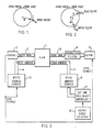
- Figure 1 shows diagrammatically the writing of a digital video signal into a memory;
- Figure 2 shows diagrammatically the writing of a digital video signal into a memory and the reading of the digital video signal from the memory; and
- Figure 3 shows in block diagrammatic form an embodiment of digital video signal processing apparatus according to the present invention.
- Before describing the embodiment, the operation of a memory forming part of the embodiment will be described with reference to Figures 1 and 2. The memory is a large random access memory (RAM) capable of storing a segment equal to several seconds, say five seconds, of an input digital video signal. That is, in a 50 Hertz television system, the RAM can store 75 frames, and in a 60 Hertz television system, the RAM can store 90 frames.
- In the embodiment to be described below, an input digital video signal derived from a live source such as a video camera is continuously written at real time speed into the RAM. The writing proceeds cyclically from the RAM start to the RAM finish, whereupon the writing immediately returns to the RAM start, and so on. At all times therefore the RAM is storing the last five seconds of the digital video signal.
- This is represented in Figure 1 where the RAM 1 is indicated as a circular store and the write position is represented as a vector W rotating with an angular velocity ωW.
- Due to the nature of the RAM 1, reading of the digital video signal can be effected independently of the writing.
- This is represented in Figure 2 where additionally the reading position is represented by a vector R rotating with an angular velocity ωR. The relative angular velocity ωΔ between writing and reading is given by:
ωW=ωR+ωΔ (1) - If ωR=ωW and reading is following writing at an angular distance ϑ, then the delay in seconds in between writing and reading will be:
ϑx n/360° (2)
where n is the store length in seconds, five seconds in the present example. ϑ can be selected to give a delay of any value up to the store length in seconds, and ϑ is preferably selected to give a delay of an integral number of frames, although it may be set to give a delay of an integral number of fields or even samples. - In the embodiment to be described, the RAM 1 forms part of a digital video signal processing apparatus which is interposed in the signal path between a video camera and a transmitter or a recorder, and which is operable to perform live cut editing. That is to say, small unwanted portions of the digital video signal can be cut from transmission or recording, the cut being made at least substantially imperceptible to a viewer.
- To accomplish this, the RAM 1 is operated with ωR=ωW and with ϑ equal to just less than 360°; that is, the maximum delay, five seconds in the present example, is used. In other words, at any given instant the oldest frame in the RAM 1 is being read. When the cut mode is triggered, ϑ is instantaneously changed to just more than 0° if a cut duration, in the present example, of five seconds is required, or to the appropriate angle between 360° and 0° if a cut of some lesser duration is required. Immediately thereafter ωR is changed to ωR-ωΔ, where ωΔ is a predetermined relative angular velocity, the value of which is selected to cause ϑ to increase back to just under 360° over a suitable time interval, which may, for example, be selected to be two minutes. ωR remains unchanged throughout.
- During the time interval while ωR is equal to ωR-ωΔ, the digital video signal will be read from the RAM 1 at a non-standard speed equal to:
(ωR-ωΔ) normal speed/ωR (3)
and to lock the read digital video signal to the system synchronizing signals it must be frame rate converted by adaptive interpolation filters of known form. - When ϑ again becomes equal to just less than 360°, the reading speed reverts to ωR, so as again to become equal to the writing speed ωW. If a further cut edit is required before this state is reached, then the duration of the cut is limited to that proportion of the store length represented by the current value of ϑ.
- Referring now to Figure 3, the embodiment of digital video signal processing apparatus comprises the RAM 1, which receives the input digital video signal in the form of write data over a
write bus 2. The write data is assumed to have been derived from a live source by a video camera and an analogue-to-digital converter generally identified in Figure 3 as a source 3. Writing in the RAM 1 is controlled by write addresses supplied over awrite address bus 4 from a write address counter 5. The write address counter 5, like the source 3, is locked to system synchronizing signals, and writing in the RAM 1 proceeds continuously, and cyclically, at a real time constant speed which is determined by the system synchronizing signals. - Read out of the digital video signal is under the control of read addresses supplied to the RAM 1 from a read address counter 6, over a read address bus 7. The read digital video signal is supplied over a
read data bus 8 to adaptive interpolation filters 9. The read addresses supplied by the read address counter 6 are field-based, that is to say, they cause reading by the RAM 1 of the data relating to the field nearest to the field addressed. In normal operation, when reading is proceeding at the same speed as writing, this means that a complete sequence of fields is read in the correct order from the RAM 1, and these fields are passed unchanged by the interpolation filters 9 to anoutput 10 which may be a digital-to-analogue converter and a transmitter, or a recorder. - The apparatus further comprises a cut and field
select controller 11 which supplies read address controls to the read address counter 6, and field polarity information to the interpolation filters 9. Finally, anoutput speed selector 12 is provided to control the cut and fieldselect controller 11. - The operation is as follows. When a cut edit is to be effected, the cut and field
select controller 11 is controlled to cause the read address counter 6 to jump the read addresses by the required amount, that is, in the terminology of Figures 1 and 2, to change ϑ, usually, but not necessarily, to just more than 0°. Thus, the unwanted segment is cut from the digital video signal read out over theread data bus 8 and supplied to the interpolation filters 9. Immediately thereafter theoutput speed selector 12 controls the cut and fieldselect controller 11, which in turn controls the read address counter 6 to slow the reading speed until reading again lags behind writing by the required amount, normally the full capacity of the RAM 1, or, in the terminology of Figures 1 and 2, until ϑ is again equal to just less than 360°. - The rate at which this is done may be fixed by the
output speed selector 12, or theoutput speed selector 12 may include a variable control permitting the rate to be varied; but the rate will normally be selected to be such that the effect is imperceptible to a viewer, and it may, for example, be arranged that reading from the RAM 1 is restored to the normal condition over a time interval of two minutes. During this interval, the readdata bus 8 will be supplying fields of the digital video signal to the interpolation filters 9 at a non-standard rate, while the cut and fieldselect controller 11 will be supplying field polarity information to the interpolation filters 9. During this interval, therefore, the interpolation filters 9 are operative to interpolate fields as necessary to provide a continuous sequence of frames, at the frequency determined by the system synchronizing signals, to theoutput 10. - The times and frequencies above are, of course, given purely by way of example.
Claims (10)
storing a segment of an input digital video signal in a random access memory (1);
writing said input digital signal in said memory (1) at a standard speed, writing proceeding cyclically from the start of said memory (1) to the finish of said memory (1), then returning to the start of said memory (1), and so on; and
reading said digital video signal from said memory (1) at said standard speed, reading normally lagging behind writing by an amount substantially equal to the capacity of said memory (1);
characterized by:
cut editing the read digital video signal by step reducing said amount by which said reading lags behind said writing; and
subsequent to a cut edit reducing the reading speed below said standard speed until the amount by which reading lags behind writing is restored to said normal amount.
a random access memory (1) capable of storing a segment of an input digital video signal;
means to write said digital video signal into said memory (1) at a standard speed, writing proceeding cyclically from the start of said memory (1) to the finish of said memory (1), then returning to the start of said memory (1), and so on; and
means to read said digital video signal from said memory (1) at said standard speed, reading normally lagging behind writing by an amount substantially equal to the capacity of said memory (1);
characterized by:
means (11, 6) to cut edit the read digital video signal by step reducing said said amount by which reading lags behind writing; and
means (12, 11, 6) operative subsequent to a cut edit to reduce the reading speed below said standard speed until the amount by which reading lags behind writing is restored to said normal amount.
Applications Claiming Priority (2)
| Application Number | Priority Date | Filing Date | Title |
|---|---|---|---|
| GB8703730 | 1987-02-18 | ||
| GB8703730A GB2201314B (en) | 1987-02-18 | 1987-02-18 | Digital video signal processing methods and apparatus |
Publications (3)
| Publication Number | Publication Date |
|---|---|
| EP0279549A2 true EP0279549A2 (en) | 1988-08-24 |
| EP0279549A3 EP0279549A3 (en) | 1990-10-31 |
| EP0279549B1 EP0279549B1 (en) | 1993-12-29 |
Family
ID=10612489
Family Applications (1)
| Application Number | Title | Priority Date | Filing Date |
|---|---|---|---|
| EP88300827A Expired - Lifetime EP0279549B1 (en) | 1987-02-18 | 1988-02-01 | Digital video signal processing methods and apparatus |
Country Status (5)
| Country | Link |
|---|---|
| US (1) | US4891715A (en) |
| EP (1) | EP0279549B1 (en) |
| JP (1) | JPH01205672A (en) |
| DE (1) | DE3886563T2 (en) |
| GB (1) | GB2201314B (en) |
Cited By (10)
| Publication number | Priority date | Publication date | Assignee | Title |
|---|---|---|---|---|
| EP0360413A2 (en) * | 1988-09-21 | 1990-03-28 | Sony Corporation | Slow motion video signal generation |
| WO1991007053A2 (en) * | 1989-11-02 | 1991-05-16 | Eastman Kodak Company | Pre-event/post-event recording in a solid state fast frame recorder |
| WO1991008644A2 (en) * | 1989-11-20 | 1991-06-13 | Eastman Kodak Company | A solid state fast frame recorder having independently selectable frame rate and exposure |
| EP0447050A2 (en) * | 1990-03-14 | 1991-09-18 | Sony Corporation | Including break slots in broadcast video signals |
| WO1991015917A1 (en) * | 1990-04-04 | 1991-10-17 | Eastman Kodak Company | Video trigger in a solid state motion analysis system |
| WO1992010065A1 (en) * | 1990-11-26 | 1992-06-11 | Eastman Kodak Company | Telephoto sensor trigger in a solid state motion analysis system |
| FR2700908A1 (en) * | 1993-01-26 | 1994-07-29 | Thomson Consumer Electronics | Buffered television receiver. |
| DE19503558A1 (en) * | 1994-02-07 | 1995-08-10 | Grass Valley Group | Spiral buffer for non-linear preparation |
| EP0799549B1 (en) * | 1994-12-23 | 2000-03-01 | Imedia Corporation | Provision of VCR-like trick modes in a video distribution system |
| EP1289291A2 (en) * | 2001-08-24 | 2003-03-05 | Matsuhita Electric Industrial Co., Ltd. | Image recording and replaying apparatus, method, program, and computer-readable recording medium recording the program |
Families Citing this family (46)
| Publication number | Priority date | Publication date | Assignee | Title |
|---|---|---|---|---|
| KR910009144Y1 (en) * | 1988-04-07 | 1991-11-25 | 삼성전자 주식회사 | F.m. signal transferring and recording system for vcr |
| JPH02132678A (en) * | 1988-11-11 | 1990-05-22 | Canon Inc | Information signal recording device |
| US5051845A (en) * | 1989-04-27 | 1991-09-24 | Gardner Larry J | Closed-loop post production process |
| US5414568A (en) * | 1989-10-23 | 1995-05-09 | Matsushita Electric Industrial Co., Ltd. | Variable speed digital signal reproducing apparatus |
| WO1991018790A1 (en) * | 1990-05-28 | 1991-12-12 | Nippon Petrochemicals Co., Ltd. | Device and method of packaging with band-like material stretched and wound around goods |
| KR940000471B1 (en) * | 1990-09-19 | 1994-01-21 | 삼성전자 주식회사 | Circuit of picture image process |
| US5241428A (en) * | 1991-03-12 | 1993-08-31 | Goldwasser Eric P | Variable-delay video recorder |
| WO1992021211A1 (en) * | 1991-05-21 | 1992-11-26 | Videotelecom Corp. | A multiple medium message recording system |
| AU4662493A (en) | 1992-07-01 | 1994-01-31 | Avid Technology, Inc. | Electronic film editing system using both film and videotape format |
| US5701383A (en) * | 1994-05-20 | 1997-12-23 | Gemstar Development Corporation | Video time-shifting apparatus |
| US5926205A (en) * | 1994-10-19 | 1999-07-20 | Imedia Corporation | Method and apparatus for encoding and formatting data representing a video program to provide multiple overlapping presentations of the video program |
| US7623754B1 (en) * | 1995-02-23 | 2009-11-24 | Avid Technology, Inc. | Motion picture recording device using digital, computer-readable non-linear media |
| US6977673B1 (en) | 1995-02-23 | 2005-12-20 | Avid Technology, Inc. | Portable moving picture recording device including switching control for multiple data flow configurations |
| US7532807B2 (en) * | 1995-04-07 | 2009-05-12 | Avid Technology, Inc. | Combined editing system and digital moving picture recording system |
| US6035367A (en) * | 1997-04-04 | 2000-03-07 | Avid Technology, Inc. | Computer file system providing looped file structure for post-occurrence data collection of asynchronous events |
| IL125141A0 (en) * | 1998-06-29 | 1999-01-26 | Nds Ltd | Advanced television system |
| US20030088872A1 (en) * | 1997-07-03 | 2003-05-08 | Nds Limited | Advanced television system |
| IL121230A (en) * | 1997-07-03 | 2004-05-12 | Nds Ltd | Intelligent electronic program guide |
| US6788882B1 (en) * | 1998-04-17 | 2004-09-07 | Timesurf, L.L.C. | Systems and methods for storing a plurality of video streams on re-writable random-access media and time-and channel- based retrieval thereof |
| US7272298B1 (en) | 1998-05-06 | 2007-09-18 | Burst.Com, Inc. | System and method for time-shifted program viewing |
| US7558472B2 (en) * | 2000-08-22 | 2009-07-07 | Tivo Inc. | Multimedia signal processing system |
| US6233389B1 (en) * | 1998-07-30 | 2001-05-15 | Tivo, Inc. | Multimedia time warping system |
| US8380041B2 (en) * | 1998-07-30 | 2013-02-19 | Tivo Inc. | Transportable digital video recorder system |
| US8577205B2 (en) * | 1998-07-30 | 2013-11-05 | Tivo Inc. | Digital video recording system |
| US6324338B1 (en) | 1998-08-07 | 2001-11-27 | Replaytv, Inc. | Video data recorder with integrated channel guides |
| US20020054752A1 (en) * | 1998-08-07 | 2002-05-09 | Anthony Wood | Video data recorder with personal channels |
| US20010043795A1 (en) * | 1998-08-07 | 2001-11-22 | Anthony Wood | Video data recorder for recording predefined format shows |
| US6647479B1 (en) | 2000-01-03 | 2003-11-11 | Avid Technology, Inc. | Computer file system providing looped file structure for post-occurrence data collection of asynchronous events |
| US20020053081A1 (en) * | 2000-10-31 | 2002-05-02 | Digitaldeck, Inc. | Adaptable programming guide for networked devices |
| US20060259926A1 (en) * | 2000-07-20 | 2006-11-16 | Digital Deck, Inc. | Adaptable programming guide for networked devices |
| US20020029384A1 (en) | 2000-07-20 | 2002-03-07 | Griggs Theodore L. | Mechanism for distributing content data |
| US20070230921A1 (en) * | 2001-04-05 | 2007-10-04 | Barton James M | Multimedia time warping system |
| US20040255327A1 (en) * | 2003-06-12 | 2004-12-16 | Digital Deck, Inc. | Media content distribution system and method |
| US9967534B1 (en) | 2004-11-19 | 2018-05-08 | Tivo Solutions Inc. | Digital video recorder video editing system |
| US8165451B2 (en) * | 2007-11-20 | 2012-04-24 | Echostar Technologies L.L.C. | Methods and apparatus for displaying information regarding interstitials of a video stream |
| US8165450B2 (en) | 2007-11-19 | 2012-04-24 | Echostar Technologies L.L.C. | Methods and apparatus for filtering content in a video stream using text data |
| US8136140B2 (en) | 2007-11-20 | 2012-03-13 | Dish Network L.L.C. | Methods and apparatus for generating metadata utilized to filter content from a video stream using text data |
| US8606085B2 (en) * | 2008-03-20 | 2013-12-10 | Dish Network L.L.C. | Method and apparatus for replacement of audio data in recorded audio/video stream |
| US8156520B2 (en) | 2008-05-30 | 2012-04-10 | EchoStar Technologies, L.L.C. | Methods and apparatus for presenting substitute content in an audio/video stream using text data |
| US20090307741A1 (en) * | 2008-06-09 | 2009-12-10 | Echostar Technologies L.L.C. | Methods and apparatus for dividing an audio/video stream into multiple segments using text data |
| US8407735B2 (en) * | 2008-12-24 | 2013-03-26 | Echostar Technologies L.L.C. | Methods and apparatus for identifying segments of content in a presentation stream using signature data |
| US8588579B2 (en) * | 2008-12-24 | 2013-11-19 | Echostar Technologies L.L.C. | Methods and apparatus for filtering and inserting content into a presentation stream using signature data |
| US8510771B2 (en) * | 2008-12-24 | 2013-08-13 | Echostar Technologies L.L.C. | Methods and apparatus for filtering content from a presentation stream using signature data |
| US8437617B2 (en) * | 2009-06-17 | 2013-05-07 | Echostar Technologies L.L.C. | Method and apparatus for modifying the presentation of content |
| US8934758B2 (en) | 2010-02-09 | 2015-01-13 | Echostar Global B.V. | Methods and apparatus for presenting supplemental content in association with recorded content |
| US11172269B2 (en) | 2020-03-04 | 2021-11-09 | Dish Network L.L.C. | Automated commercial content shifting in a video streaming system |
Citations (3)
| Publication number | Priority date | Publication date | Assignee | Title |
|---|---|---|---|---|
| FR2371837A1 (en) * | 1976-11-22 | 1978-06-16 | Bts Systementwicklungs Gmbh | METHOD AND DEVICE FOR THE CONVERSION OF IMAGE FREQUENCIES |
| GB2098021A (en) * | 1981-05-06 | 1982-11-10 | Sony Corp | Digital television apparatuses |
| EP0153820A2 (en) * | 1984-02-22 | 1985-09-04 | Sony Corporation | Digital television signal processing apparatus |
Family Cites Families (10)
| Publication number | Priority date | Publication date | Assignee | Title |
|---|---|---|---|---|
| US4134128A (en) * | 1976-03-19 | 1979-01-09 | Rca Corporation | Television picture size altering apparatus |
| GB1576461A (en) * | 1977-02-01 | 1980-10-08 | Quantel Ltd | Control arrangement for video synchronisers |
| JPS5646215A (en) * | 1979-09-21 | 1981-04-27 | Natsuku:Kk | Method and device for producing animation |
| US4394745A (en) * | 1980-04-11 | 1983-07-19 | Sony Corporation | Video editing apparatus |
| JPS5760576A (en) * | 1980-09-26 | 1982-04-12 | Hitachi Ltd | Pcm recorder |
| US4685003A (en) * | 1983-12-02 | 1987-08-04 | Lex Computing & Management Corporation | Video composition method and apparatus for providing simultaneous inputting and sorting of video source material |
| US4698664A (en) * | 1985-03-04 | 1987-10-06 | Apert-Herzog Corporation | Audio-visual monitoring system |
| US4706135A (en) * | 1986-01-10 | 1987-11-10 | Tokai Television Broadcasting Company Limited | Video recording apparatus with editing and mixing of delayed monitored video signal using equidistant record, read and erase heads |
| JPS62206976A (en) * | 1986-03-06 | 1987-09-11 | Pioneer Electronic Corp | Control device for video memory |
| US4785359A (en) * | 1986-10-06 | 1988-11-15 | Eastman Kodak Company | Dual purpose memory for time division multiplexing and time base error correction |
-
1987
- 1987-02-18 GB GB8703730A patent/GB2201314B/en not_active Expired - Lifetime
-
1988
- 1988-02-01 EP EP88300827A patent/EP0279549B1/en not_active Expired - Lifetime
- 1988-02-01 DE DE3886563T patent/DE3886563T2/en not_active Expired - Fee Related
- 1988-02-10 US US07/154,229 patent/US4891715A/en not_active Expired - Lifetime
- 1988-02-12 JP JP63030142A patent/JPH01205672A/en active Pending
Patent Citations (3)
| Publication number | Priority date | Publication date | Assignee | Title |
|---|---|---|---|---|
| FR2371837A1 (en) * | 1976-11-22 | 1978-06-16 | Bts Systementwicklungs Gmbh | METHOD AND DEVICE FOR THE CONVERSION OF IMAGE FREQUENCIES |
| GB2098021A (en) * | 1981-05-06 | 1982-11-10 | Sony Corp | Digital television apparatuses |
| EP0153820A2 (en) * | 1984-02-22 | 1985-09-04 | Sony Corporation | Digital television signal processing apparatus |
Cited By (23)
| Publication number | Priority date | Publication date | Assignee | Title |
|---|---|---|---|---|
| EP0360413A2 (en) * | 1988-09-21 | 1990-03-28 | Sony Corporation | Slow motion video signal generation |
| WO1990003704A1 (en) * | 1988-09-21 | 1990-04-05 | Sony Corporation | Slow motion video signal generation |
| EP0360413A3 (en) * | 1988-09-21 | 1990-05-02 | Sony Corporation | Slow motion video signal generation |
| US4987489A (en) * | 1988-09-21 | 1991-01-22 | Sony Corporation | Apparatus for generating an interlaced slow motion video output signal by spatial and temporal interpolation |
| WO1991007053A3 (en) * | 1989-11-02 | 1991-06-27 | Eastman Kodak Co | Pre-event/post-event recording in a solid state fast frame recorder |
| WO1991007053A2 (en) * | 1989-11-02 | 1991-05-16 | Eastman Kodak Company | Pre-event/post-event recording in a solid state fast frame recorder |
| US5140436A (en) * | 1989-11-02 | 1992-08-18 | Eastman Kodak Company | Pre-event/post-event recording in a solid state fast frame recorder |
| WO1991008644A2 (en) * | 1989-11-20 | 1991-06-13 | Eastman Kodak Company | A solid state fast frame recorder having independently selectable frame rate and exposure |
| WO1991008644A3 (en) * | 1989-11-20 | 1991-08-08 | Eastman Kodak Co | A solid state fast frame recorder having independently selectable frame rate and exposure |
| US5196938A (en) * | 1989-11-20 | 1993-03-23 | Eastman Kodak Company | Solid state fast frame recorder having independently selectable frame rate and exposure |
| EP0447050A3 (en) * | 1990-03-14 | 1993-05-19 | Sony Corporation | Including break slots in broadcast video signals |
| EP0447050A2 (en) * | 1990-03-14 | 1991-09-18 | Sony Corporation | Including break slots in broadcast video signals |
| WO1991015917A1 (en) * | 1990-04-04 | 1991-10-17 | Eastman Kodak Company | Video trigger in a solid state motion analysis system |
| WO1992010065A1 (en) * | 1990-11-26 | 1992-06-11 | Eastman Kodak Company | Telephoto sensor trigger in a solid state motion analysis system |
| FR2700908A1 (en) * | 1993-01-26 | 1994-07-29 | Thomson Consumer Electronics | Buffered television receiver. |
| WO1994017626A1 (en) * | 1993-01-26 | 1994-08-04 | Thomson Consumer Electronics S.A. | Television set with a buffer memory |
| DE19503558A1 (en) * | 1994-02-07 | 1995-08-10 | Grass Valley Group | Spiral buffer for non-linear preparation |
| DE19503558C2 (en) * | 1994-02-07 | 1999-01-21 | Grass Valley Group | Spiral buffer for non-linear preparation |
| EP0799549B1 (en) * | 1994-12-23 | 2000-03-01 | Imedia Corporation | Provision of VCR-like trick modes in a video distribution system |
| US6434748B1 (en) | 1994-12-23 | 2002-08-13 | Imedia Corporation | Method and apparatus for providing VCR-like “trick mode” functions for viewing distributed video data |
| EP1289291A2 (en) * | 2001-08-24 | 2003-03-05 | Matsuhita Electric Industrial Co., Ltd. | Image recording and replaying apparatus, method, program, and computer-readable recording medium recording the program |
| EP1289291A3 (en) * | 2001-08-24 | 2004-04-14 | Matsuhita Electric Industrial Co., Ltd. | Image recording and replaying apparatus, method, program, and computer-readable recording medium recording the program |
| US7215873B2 (en) | 2001-08-24 | 2007-05-08 | Matsushita Electric Industrial Co., Ltd. | Image recording and replaying apparatus, method, program, and computer-readable recording medium recording the program |
Also Published As
| Publication number | Publication date |
|---|---|
| DE3886563T2 (en) | 1994-06-30 |
| GB8703730D0 (en) | 1987-03-25 |
| DE3886563D1 (en) | 1994-02-10 |
| US4891715A (en) | 1990-01-02 |
| EP0279549B1 (en) | 1993-12-29 |
| GB2201314B (en) | 1991-02-27 |
| JPH01205672A (en) | 1989-08-18 |
| EP0279549A3 (en) | 1990-10-31 |
| GB2201314A (en) | 1988-08-24 |
Similar Documents
| Publication | Publication Date | Title |
|---|---|---|
| EP0279549B1 (en) | Digital video signal processing methods and apparatus | |
| US5717829A (en) | Pitch control of memory addressing for changing speed of audio playback | |
| US5696868A (en) | Apparatus and method for recording/playing back broadcasting signal | |
| EP0722224A2 (en) | Method for setting addresses for electronic appliances | |
| CA2017876A1 (en) | Apparatus for controlling a television receiver | |
| EP0153820B1 (en) | Digital television signal processing apparatus | |
| US5162903A (en) | Apparatus for switching between two asynchronous video signals | |
| US5181114A (en) | Including break slots in broadcast video signals | |
| JP2913507B2 (en) | Video signal processing and video store | |
| US4757531A (en) | Encryption of television signals | |
| JP2001036861A (en) | Program recorder and program recording medium | |
| EP0524798B1 (en) | Video signal processing apparatus | |
| US4528603A (en) | Drum servo control with reduced head phase error during editing | |
| US5329366A (en) | Time base corrector for video signal | |
| US4876734A (en) | Image signal processing method and apparatus | |
| US4974074A (en) | Video signal processing apparatus for a stereoscopic video image | |
| US5559607A (en) | Apparatus for controlling reproduction speed for laser disc player | |
| JPS5989085A (en) | Reproducer of digital television signal | |
| US5257104A (en) | Video signal processing apparatus | |
| US5677740A (en) | Video receiver for storing compressed and encoded audio-visual data | |
| JPH0310179B2 (en) | ||
| US5285288A (en) | Video signal reproducing apparatus with time base corrector | |
| KR970005642B1 (en) | Variable speed data recording and reproducing circuit of vcr | |
| JP2844765B2 (en) | Video signal playback device | |
| US4994924A (en) | Reproducing processor allowing selective inhibition of dropout compensation and video signal correction processing |
Legal Events
| Date | Code | Title | Description |
|---|---|---|---|
| PUAI | Public reference made under article 153(3) epc to a published international application that has entered the european phase |
Free format text: ORIGINAL CODE: 0009012 |
|
| AK | Designated contracting states |
Kind code of ref document: A2 Designated state(s): DE FR GB NL |
|
| PUAL | Search report despatched |
Free format text: ORIGINAL CODE: 0009013 |
|
| AK | Designated contracting states |
Kind code of ref document: A3 Designated state(s): DE FR GB NL |
|
| 17P | Request for examination filed |
Effective date: 19910302 |
|
| 17Q | First examination report despatched |
Effective date: 19921207 |
|
| GRAA | (expected) grant |
Free format text: ORIGINAL CODE: 0009210 |
|
| AK | Designated contracting states |
Kind code of ref document: B1 Designated state(s): DE FR GB NL |
|
| REF | Corresponds to: |
Ref document number: 3886563 Country of ref document: DE Date of ref document: 19940210 |
|
| ET | Fr: translation filed | ||
| PLBE | No opposition filed within time limit |
Free format text: ORIGINAL CODE: 0009261 |
|
| STAA | Information on the status of an ep patent application or granted ep patent |
Free format text: STATUS: NO OPPOSITION FILED WITHIN TIME LIMIT |
|
| 26N | No opposition filed | ||
| REG | Reference to a national code |
Ref country code: GB Ref legal event code: IF02 |
|
| PGFP | Annual fee paid to national office [announced via postgrant information from national office to epo] |
Ref country code: GB Payment date: 20050126 Year of fee payment: 18 |
|
| PGFP | Annual fee paid to national office [announced via postgrant information from national office to epo] |
Ref country code: DE Payment date: 20050127 Year of fee payment: 18 |
|
| PGFP | Annual fee paid to national office [announced via postgrant information from national office to epo] |
Ref country code: NL Payment date: 20050203 Year of fee payment: 18 |
|
| PGFP | Annual fee paid to national office [announced via postgrant information from national office to epo] |
Ref country code: FR Payment date: 20050208 Year of fee payment: 18 |
|
| PG25 | Lapsed in a contracting state [announced via postgrant information from national office to epo] |
Ref country code: GB Free format text: LAPSE BECAUSE OF NON-PAYMENT OF DUE FEES Effective date: 20060201 |
|
| PG25 | Lapsed in a contracting state [announced via postgrant information from national office to epo] |
Ref country code: NL Free format text: LAPSE BECAUSE OF NON-PAYMENT OF DUE FEES Effective date: 20060901 Ref country code: DE Free format text: LAPSE BECAUSE OF NON-PAYMENT OF DUE FEES Effective date: 20060901 |
|
| GBPC | Gb: european patent ceased through non-payment of renewal fee |
Effective date: 20060201 |
|
| NLV4 | Nl: lapsed or anulled due to non-payment of the annual fee |
Effective date: 20060901 |
|
| REG | Reference to a national code |
Ref country code: FR Ref legal event code: ST Effective date: 20061031 |
|
| PG25 | Lapsed in a contracting state [announced via postgrant information from national office to epo] |
Ref country code: FR Free format text: LAPSE BECAUSE OF NON-PAYMENT OF DUE FEES Effective date: 20060228 |