EP0279507A2 - Control system for motor vehicle suspension unit - Google Patents
Control system for motor vehicle suspension unit Download PDFInfo
- Publication number
- EP0279507A2 EP0279507A2 EP88300286A EP88300286A EP0279507A2 EP 0279507 A2 EP0279507 A2 EP 0279507A2 EP 88300286 A EP88300286 A EP 88300286A EP 88300286 A EP88300286 A EP 88300286A EP 0279507 A2 EP0279507 A2 EP 0279507A2
- Authority
- EP
- European Patent Office
- Prior art keywords
- suspension unit
- suspension
- force
- vehicle
- adjustable
- Prior art date
- Legal status (The legal status is an assumption and is not a legal conclusion. Google has not performed a legal analysis and makes no representation as to the accuracy of the status listed.)
- Withdrawn
Links
Images





Classifications
-
- B—PERFORMING OPERATIONS; TRANSPORTING
- B60—VEHICLES IN GENERAL
- B60G—VEHICLE SUSPENSION ARRANGEMENTS
- B60G17/00—Resilient suspensions having means for adjusting the spring or vibration-damper characteristics, for regulating the distance between a supporting surface and a sprung part of vehicle or for locking suspension during use to meet varying vehicular or surface conditions, e.g. due to speed or load
- B60G17/015—Resilient suspensions having means for adjusting the spring or vibration-damper characteristics, for regulating the distance between a supporting surface and a sprung part of vehicle or for locking suspension during use to meet varying vehicular or surface conditions, e.g. due to speed or load the regulating means comprising electric or electronic elements
- B60G17/0152—Resilient suspensions having means for adjusting the spring or vibration-damper characteristics, for regulating the distance between a supporting surface and a sprung part of vehicle or for locking suspension during use to meet varying vehicular or surface conditions, e.g. due to speed or load the regulating means comprising electric or electronic elements characterised by the action on a particular type of suspension unit
- B60G17/0157—Resilient suspensions having means for adjusting the spring or vibration-damper characteristics, for regulating the distance between a supporting surface and a sprung part of vehicle or for locking suspension during use to meet varying vehicular or surface conditions, e.g. due to speed or load the regulating means comprising electric or electronic elements characterised by the action on a particular type of suspension unit non-fluid unit, e.g. electric motor
-
- B—PERFORMING OPERATIONS; TRANSPORTING
- B60—VEHICLES IN GENERAL
- B60G—VEHICLE SUSPENSION ARRANGEMENTS
- B60G17/00—Resilient suspensions having means for adjusting the spring or vibration-damper characteristics, for regulating the distance between a supporting surface and a sprung part of vehicle or for locking suspension during use to meet varying vehicular or surface conditions, e.g. due to speed or load
- B60G17/015—Resilient suspensions having means for adjusting the spring or vibration-damper characteristics, for regulating the distance between a supporting surface and a sprung part of vehicle or for locking suspension during use to meet varying vehicular or surface conditions, e.g. due to speed or load the regulating means comprising electric or electronic elements
- B60G17/018—Resilient suspensions having means for adjusting the spring or vibration-damper characteristics, for regulating the distance between a supporting surface and a sprung part of vehicle or for locking suspension during use to meet varying vehicular or surface conditions, e.g. due to speed or load the regulating means comprising electric or electronic elements characterised by the use of a specific signal treatment or control method
-
- B—PERFORMING OPERATIONS; TRANSPORTING
- B60—VEHICLES IN GENERAL
- B60G—VEHICLE SUSPENSION ARRANGEMENTS
- B60G17/00—Resilient suspensions having means for adjusting the spring or vibration-damper characteristics, for regulating the distance between a supporting surface and a sprung part of vehicle or for locking suspension during use to meet varying vehicular or surface conditions, e.g. due to speed or load
- B60G17/06—Characteristics of dampers, e.g. mechanical dampers
-
- B—PERFORMING OPERATIONS; TRANSPORTING
- B60—VEHICLES IN GENERAL
- B60G—VEHICLE SUSPENSION ARRANGEMENTS
- B60G21/00—Interconnection systems for two or more resiliently-suspended wheels, e.g. for stabilising a vehicle body with respect to acceleration, deceleration or centrifugal forces
- B60G21/02—Interconnection systems for two or more resiliently-suspended wheels, e.g. for stabilising a vehicle body with respect to acceleration, deceleration or centrifugal forces permanently interconnected
- B60G21/04—Interconnection systems for two or more resiliently-suspended wheels, e.g. for stabilising a vehicle body with respect to acceleration, deceleration or centrifugal forces permanently interconnected mechanically
- B60G21/05—Interconnection systems for two or more resiliently-suspended wheels, e.g. for stabilising a vehicle body with respect to acceleration, deceleration or centrifugal forces permanently interconnected mechanically between wheels on the same axle but on different sides of the vehicle, i.e. the left and right wheel suspensions being interconnected
- B60G21/055—Stabiliser bars
- B60G21/0551—Mounting means therefor
- B60G21/0553—Mounting means therefor adjustable
- B60G21/0556—Mounting means therefor adjustable including a releasable coupling
-
- B—PERFORMING OPERATIONS; TRANSPORTING
- B60—VEHICLES IN GENERAL
- B60G—VEHICLE SUSPENSION ARRANGEMENTS
- B60G2202/00—Indexing codes relating to the type of spring, damper or actuator
- B60G2202/20—Type of damper
- B60G2202/22—Rotary Damper
-
- B—PERFORMING OPERATIONS; TRANSPORTING
- B60—VEHICLES IN GENERAL
- B60G—VEHICLE SUSPENSION ARRANGEMENTS
- B60G2202/00—Indexing codes relating to the type of spring, damper or actuator
- B60G2202/20—Type of damper
- B60G2202/23—Friction Damper
-
- B—PERFORMING OPERATIONS; TRANSPORTING
- B60—VEHICLES IN GENERAL
- B60G—VEHICLE SUSPENSION ARRANGEMENTS
- B60G2202/00—Indexing codes relating to the type of spring, damper or actuator
- B60G2202/40—Type of actuator
- B60G2202/42—Electric actuator
Definitions
- This invention relates to an adjustable motor vehicle suspension comprising an adjustable suspension unit and a control system therefor.
- Adjustable suspension units and particularly adjustable suspension units with adjustable damping capability have been the subject of numerous patents.
- U.S. patent 3,603,612 discloses an adjustable shock absorber in which an electronic control valve is operable to change the damping capability of the unit as a function of vehicle speed.
- Adjustable shock absorbers have been employed with a variety of control schemes.
- An example of one such control scheme is disclosed in U.S. patent 4,333,668 in which damping is controlled as a function, inter alia , as a function of body roll.
- body roll refers to a potentially objectionable tilting or leaning of an automobile body from its normal ride attitude during turning, stopping, braking, or other maneuvers.
- U.S. patent 4,564,215 discloses a control system in which a bistable suspension unit is switchable from a soft state to a hard state.
- U.S. patent 4,589,676 discloses a control system which senses road undulations and changes the damping characteristics of the suspension unit accordingly.
- This device includes hydraulic means for damping road-induced vibrations. Although such means may be satisfactory under certain conditions, hydraulic suspension units are generally incapable of achieving fast response in the 10 to 15 Hz. frequency regime which characterizes the vertical suspension motion of many modern motor vehicles.
- U.S. patents 3,913,938; 3,992,039; 4,364,574; 4,453,725; and 4,591,185 each disclose a type of suspension system including vehicle height or level control capability. Each of these devices is either hydraulically or pneumatically actuated and each functions at a steady state to control the height of a vehicle body with respect to the balance of a suspension system. None of these systems is capable of controlling the suspension unit in the manner herein described while the suspension unit is oscillating at the natural frequency of the suspension system, which includes the suspension unit, the wheel and tire assembly, and any other dampers or spring elements.
- U.S. patent 3,606,365 discloses an active suspension system for a vehicle in which the vehicle body is supported by a piston and cylinder arrangement. Oscillations of the body are counteracted by manipulating the volume of fluid on either side of the piston.
- This system too, is not capable of high frequency response because of the lag time associated with the various valves and other hydraulic devices included in the system.
- Such hydraulic devices are generally incapable of accurately controlling a suspension system during a half cycle stroke because of a non-linear relationship between the force the hydraulic damper generates and the input control signals. This non-linearity results from the characteristics of the hydraulic valves, from the compressibility of the hydraulic fluid, and other factors, and makes it difficult to control damping force independent of damper velocity.
- sliding friction dampers were known at the dawn of the automotive age.
- U.S. patent 875,759 discloses a sliding friction shock absorber which is adjustable by means of either a wedge or a four bar link mechanism.
- Other types of sliding friction shock absorbers are shown in U.S. patents 1,671,658; 3,052,458; 3,866,724; and 3,990,542.
- French patent 1,143,703 discloses yet another type of sliding friction shock absorber.
- It is an object of the present invention to provide an adjustable motor vehicle suspension comprising an adjustable suspension unit and a control system therefor which will permit dynamic adjustment of the damping of the suspension unit depending upon which stroke of a two stroke cycle the suspension unit is operating in.
- It is another object of the present invention to provide an adjustable motor vehicle suspension comprising a control system which will allow the vehicle suspension to counteract body roll during cornering, brake dive, and acceleration squat.
- It is yet another object of the present invention to provide an adjustable motor vehicle suspension comprising a control system which will counteract vertical oscillations of the vehicle body in response to inputs from the suspension.
- control system can be used to control sliding friction shock absorbers capable of producing maximum force at a relative suspension velocity of zero (i.e., when the velocity of one part of the suspension unit is zero with respect to the other part of the same suspension unit.)
- control system may be employed to control sliding friction shock absorbers or other types of adjustable suspension units having lower lag time characteristics.
- a suspension according to the present invention uses the resilient energy of the suspension system to counteract undesired movement of the vehicle body.
- this suspension may be used to produce high damping force inputs to the vehicle body without requiring power input from a hydraulic pump or other high power absorbing device.
- a suspension system for a motor vehicle having a body and road wheels supporting said body, with said road wheels being connected to said body by said suspension system, said suspension system comprising, an adjustable suspension unit (10) comprising a damping device (13) and adjustment means (12,14) for adjusting the damping force produced by said damping device in response to a control signal, sensor means (26) for predicting acceleration of said vehicle, and a control system (20,22,24) operatively connected to said adjustment means for controlling the damping of said adjustable suspension unit in response to a predicted acceleration signal from said sensor means so that said suspension unit will resist roll of said body resulting from said acceleration, said control system comprising means (20) for modulating the force imposed upon said body by said suspension unit by controlling the force developed by said damping device according to the particular stroke of the cycle in which said suspension unit is operating, so that said suspension unit will exert a net force upon said body in a direction tending to resist roll of said body in response to said acceleration.
- a suspension system for a motor vehicle having a body and road wheels supporting said body, with said road wheels being connected to said body by said suspension system, said suspension system comprising an adjustable suspension unit comprising a damping device and adjustment means for adjusting the damping force produced by said damping device in response to a control signal, sensor means for detecting vertical motion of said body, and a control system operatively connected to said adjustment means for controlling the damping of said adjustable suspension unit in response to a vertical motion signal from said sensor means so that said suspension unit will resist vertical motion of said body, said control system comprising means for modulating the force imposed upon said body by said suspension unit by controlling the force developed by said damping device according to the particular stroke of the cycle in which said suspension unit is operating, so that said suspension unit will exert a net force upon said body in a direction tending to resist sensed vertical motion of said body.
- the sensor means for predicting acceleration of the vehicle comprises a sensor activated by operation of a braking system associated with the vehicle, or a sensor activated by operation of a throttle mechanism operatively connected with a power plant incorporated in the vehicle, or a sensor operatively connected with a steering system incorporated in the vehicle.
- the sensor means for predicting acceleration of the vehicle may comprise an accelerometer as well.
- Said control system comprises means for determining the particular stroke of the two-stroke cycle in which the suspension unit is operating and means for controlling the force produced by the suspension unit during any particular stroke of the suspension unit such that the suspension unit will, if located on that side of the body tending to move downward during body roll movement, apply a net force in an upward direction against the body, whereas in the event that the suspension is located on a side of the body tending to move upward during roll movement, the suspension unit will be controlled so as to apply a downwardly directed force against the body.
- the means for determining the particular stroke of the cycle in which the suspension unit is operating comprises means for sensing relative motion of at least a portion of the suspension unit with respect to the body of the vehicle.
- the means for determining the particular stroke of the cycle may alternatively comprise means for sensing relative motion between two elements of the suspension unit.
- the adjusting means may further comprise means for sensing the magnitude of the damping force developed by the suspension unit.
- the present control system includes sensor means for detecting vertical motion of the vehicle body.
- This sensor means may comprise a radio frequency ranging device.
- a control system modulates the force developed by the suspension unit according to the magnitude of the velocity of the vehicle's body with respect to a horizontal global reference plane.
- the force developed by the suspension unit may be modulated according to the rate of acceleration of the body with respect to the surface the vehicle is being operated upon.
- a method for operating a suspension unit having adjustable damping capability includes the steps of detecting vertical motion of the vehicle body with respect to a horizontal global reference plane and adjusting the force developed by the suspension unit according to the particular stroke in which the suspension unit is operating, so that the suspension unit will exert a net force upon the body in a direction tending to resist vertical motion of the body.
- the suspension unit is preferably controlled so that it will apply a downwardly directed force against the body when the body is moving in an upward direction, and an upwardly directed force against the body when the body is moving in a downward direction.
- the force developed by the suspension unit is preferably controlled so that this force is proportional to the vertical velocity of the body with respect to the surface upon which the vehicle is being operated.
- the suspension unit is preferably operated so that when a downwardly directed force against the body is required, the suspension unit will be adjusted to produce a greater amount of force when a road wheel and tire assembly operatively associated with the suspension unit is moving in a direction away from the body of the vehicle and a lesser amount of force when the road wheel and tire assembly is moving in a direction toward the body of the vehicle.
- the suspension unit when it is desired to apply an upwardly directed force against the body, the suspension unit will be adjusted so as to produce a lesser amount of force when the road wheel and tire assembly operatively associated with the suspension unit is moving in a direction away from the body of the vehicle and a greater amount of force when the road wheel and tire assembly is moving in a direction toward the body of the vehicle.
- the disclosed method for operating an adjustable suspension unit describes steps for operating the unit including the steps of determining the particular stroke of the two-stroke cycle in which the suspension unit is operating and adjusting the force developed by the suspension unit according to the particular stroke of the cycle in which the suspension unit is operating, so that the suspension unit will exert a net force upon the vehicle body in a desired direction.
- adjustable suspension unit 10 comprises a portion 12 which is to be attached to a vehicle body and a portion 14 attached to a portion of the suspension which is more closely connected with the wheel and tire assembly.
- damping section 13 lies between portions 12 and 14 of adjustable suspension unit 10.
- Damping section 13 preferably comprises a sliding friction damping device such as those shown in Figures 3, 4, 5, 6 and 7, or may preferably comprise a hydraulic adjustable damping unit or other type of adjustable damping unit.
- Force sensor 16 is attached to portion 12 of the adjustable damping unit 10.
- the force sensor may comprise a piezoelectric device or load cell, or other types of force sensors known to those skilled in the art and suggested by this disclosure. Those skilled in the art will appreciate in view of this disclosure that other locations may be employed for mounting the force sensor.
- the purpose of the force sensor is to measure the amount of damping force developed by adjustable suspension unit 10 and to transmit this information to the microprocessor and to the suspension unit operator.
- motion sensor 18 The movement of portions 12 and 14 of adjustable suspension unit 10 with respect to each other is detected by motion sensor 18.
- This sensor may be constructed according to the several methods known to those skilled in the art and suggested by this disclosure.
- the sensor may comprise a Hall Effect sensor such as those currently employed in some automotive vehicles, or the sensor may preferably may comprise a linear variable differential transformer (LVDT), or other types of sensors known to those skilled in the art and suggested by this disclosure.
- LVDT linear variable differential transformer
- This information tells the control system at any given instance whether the adjustable suspension unit is moving in a jounce direction, i.e., in a direction wherein its length is decreasing, or in a rebound direction, i.e., in a direction wherein its length is increasing.
- Sensor 18 also discloses to the control system the precise position of suspension unit 10 in terms of its fully-extended, full-contracted states. This information is important because the present control system is intended to control the damping force generated by adjustable suspension unit 10 according to the particular stroke of the cycle in which the adjustable suspension unit is operating.
- adjustable suspension unit 10 is considered to operate in a cycle.
- the cycle has two strokes.
- the first stroke herein referred to as a rebound stroke
- the second stroke herein referred to as the jounce stroke
- the adjustable suspension unit is attached at one end to one or more wheel and tire assemblies shown at 28 in Figure 2 as well as being attached to the body of the vehicle at the other end of the suspension unit.
- a system according to the present invention may comprise actuator 20, suspension unit operator 22, microprocessor 24, and acceleration sensor 26.
- Actuator 20 functions to control the force developed by adjustable suspension unit 10. In the case of the suspension units described herein, this control results from the adjustment, by the actuator, of a sliding friction element contained within the adjustable suspension unit. Two types of sliding friction elements are shown in Figures 4-7 herein.
- Suspension unit operator 22 receives inputs from force sensor 16, motion sensor 18 and microprocessor 24.
- Microprocessor 24 outputs to suspension unit operator 22 a desired force signal.
- Suspension operator 22 knowing the measured force being generated by the adjustable suspension unit at any time by virtue of the signals from force sensor 16, then outputs the signal to actuator 20 to direct the actuator to adjust the damping force produced by adjustable suspension unit 10.
- Microprocessor 24 may receive various inputs from accleration sensor 26.
- acceleration sensor 26 may be arranged to provide an input to microprocessor 24 relating to turning of the vehicle, or brake operation of the vehicle, or operation of the vehicle throttle, or vertical motion of the vehicle, or other inputs.
- acceleration sensor 26 could comprise a variety of sensors such as an accelerometer, a brake sensor such as a pressure sensor or electronic switch associated with the brake system of the vehicle, or other types of sensors such as a throttle position sensor included in a throttle mechanism operatively connected with the vehicle power plant.
- the steering sensor and associated control system disclosed in U.S. patent 4,621,833, which is hereby incorporated by reference herein, comprises yet another type of sensor useful for predicting lateral acceleration in a vehicle
- microprocessor 24 and its peripheral equipment could be structured according to several different architectures.
- microprocessor 24 is configured so that a control program is sequentially read for each unit command from a read-only memory (ROM) which stores preset control programs.
- Unit commands are executed by a central processing unit (CPU).
- the microprocessor integrally includes an input-output control circuit (I/O) for exchanging data with external devices and a random access memory (RAM) for temporarily holding data while the data are being processed.
- I/O input-output control circuit
- RAM random access memory
- a vehicle including body 21 and four wheel and tire assemblies 28 has adjustable suspension units 10 mounted generally between the wheel and tire assemblies and the vehicle body.
- a MacPherson strut suspension is illustrated at the front of the vehicle, whereas a Hotchkiss drive is shown at the rear.
- FIG. 2 shows microprocessor 24 mounted in the rear of the vehicle.
- the microprocessor enclosure also includes suspension unit operator 22.
- suspension unit operator 22 could be integrated with an engine control computer, or any other type of on-board computer system within the vehicle.
- multiple suspension unit operators may be employed so as to independently control each suspension unit with a unique operator.
- adjustable suspension units 10 wheel and tire assemblies 28 are connected by means of suspensions 23 to adjustable suspension units 10. Although four adjustable suspension units are shown on the vehicle in Figure 2, it will be appreciated in view of this disclosure that adjustable units could be used at fewer than four locations in the vehicle. For example, if it is determined that a particular vehicle is particularly prone to fore and aft pitching, but not to roll during cornering, it may be desirable to equip the vehicle with adjustable suspension units at only the front or the rear of the vehicle.
- the system shown in Figure 2 is powered by the vehicle's battery, 30.
- a plurality of sensors is employed to provide the system with information it needs in order to operate adjustable suspension units 10.
- steering sensor 32 is shown.
- This sensor functions as described in U.S. patent 4,621,833 which was previously incorporated by reference into this document.
- Brake sensor 34 is also shown, as is speed sensor 38.
- the brake, speed, and steering sensors may all be used for the purpose of detecting acceleration of the vehicle.
- speed sensor 38 detects vehicle speed and the data therefrom may be manipulated by microprocessor 24 to calculate vehicle velocity and acceleration.
- Brake sensor 34 detects operation of the vehicle's brake system and therefore will detect linear acceleration (or deceleration) of the vehicle due to application of the brakes.
- Throttle position sensor 40 may also be used to detect acceleration because application of the throttle will normally cause the vehicle's speed to increase.
- Steering sensor 32 may be used to predict lateral acceleration of the vehicle, because movement of the steering wheel will almost always precede the lateral acceleration occasioned by a subsequent turn.
- a single accelerometer, 36 is shown as being mounted in the front of the vehicle in the approximate vicinity of the engine compartment. It could be understood that multiple accelerometers could be employed according to the present inventuion with one or more accelerometers at the front of the vehicle and one or more accelerometers at the rear of the vehicle. If desired, an accelerometer could be positioned adjacent to each adjustable suspension unit 10. Alternatively, sensors could be deployed at the right and left sides (i.e., on the passenger and driver sides of the vehicle) to allow detection of body roll. It will be appreciated in view of this disclosure that the previously described accelerometers could be employed to detect acceleration in several mutually perpendicular planes such as laterally, longitudinally, or vertically.
- adjustable suspension unit 10 is mounted to body 21 of the vehicle. Housing 48 of the adjustable suspension unit is attached to the body by means of a bracket or other conventional attaching techniques known to those skilled in the art. Adjustable suspension unit 10 is connected to the balance of the suspension according to any of several well known constructions by means of link 44 which is attached to pitman arm 42. The pitman arm is rigidly attached to rotatable shaft 46 which is pivoted within housing 48.
- bearing 47 is provided at one end of rotatable shaft 46.
- the opposite end of rotatable shaft 46 is pivoted within plunger 54 (See Figure 4).
- Rotatable shaft 46 has a plurality of rotors 50 keyed thereto.
- Figure 5 shows rotors 50 and this keying feature in greater detail.
- Rotors 50 rotate with rotatable shaft 46 as rotatable shaft 46 is driven by pitman arm 42, link 44 and the balance of the suspension attached to these components.
- a plurality of stators 52 is interleaved with rotors 50.
- Stator plates 52 are non-rotatably mounted within outer housing 48. Stator plates 52 are urged to clampingly engage rotor plates 50 by plunger 54 so that rotation of rotatable shaft 46 and rotor plates 50 is thereby resisted.
- adjustable suspension unit 10 resists jounce and rebound motion of the suspension transmitted by link 44 to pitman arm 42. The measured amount of resistance to suspension motion (damping force) is fed into suspension unit operator 22 by means of force sensor 16.
- the amount of damping force developed by suspension unit 10 shown in Figure 4 is controlled by plunger 54 in conjunction with crosslink 56, toggle link 58, lead screw 60, and torque motor 62.
- Plunger 54 presses axially upon the interleaved stator and rotor plates so as to develop a normal force between the stator and rotor plates. Accordingly, the amount of friction acting between the rotor and stator plates and the resultant damping force developed by the suspension unit is controlled.
- Plunger 54 is loaded into the stator and rotor plate stack by means of crosslink 56, which is pivoted to outer housing 48 by means of crosslink pivot 57.
- Crosslink 56 is connected to a driving mechanism comprising lead screw 60 and torque motor 62 by means of toggle link 58.
- Toggle link 58 has a pivot at either end allowing lead screw 60 and torque motor 62 to move the crosslink 56 in and out so as to either clamp tighter or more loosely plunger 54 and thereby, the stator and rotor stack.
- Lead screw 60 and torque motor 62 advantageously control the adjustable suspension unit because only very small displacements of plunger 54 are needed to change the frictional force developed between the stator and rotor plates. This allows very high amplification of the actuator force with minimum actuator displacement. Thus, a small torque motor and lead screw assembly may be used while at the same time maintaining a high frequency response. Accordingly, the relationship between the force developed by the adjustable suspension unit and the electrical control signal is linear.
- the damping force developed by the adjustable suspension is therefore linearly related to the sliding frictional force through the coefficient of friction. Because the motor torque produced by the torque motor for small displacements is linearly proportional to the input current, the force produced by the damper is proportional to the current driving the motor. As a result, the frequency response of the suspension unit is limited primarily by the speed with which the current can be changed in the motor. Because this current can be changed very rapidly a suspension unit according to the principles described herein can have very fast response characteristics. In addition, the damping force developed by a suspension unit operated according to the principles described herein is independent of velocity of the suspension unit's motion in the jounce and rebound directions. A damper operated according to the present scheme can generate its maximum force at zero suspension velocity or at maximum suspension velocity or at any intermediate velocity. Because the damping is adjustable, moreover, the damper can be manipulated to provide zero damping if required.
- FIG. 6 A second embodiment of a damper useful for practicing the present invention is shown in Figures 6 and 7.
- piston rod 66 is attached to vehicle body 21.
- the lower end of suspension unit 10, including cylindrical tube 71, is attached to suspension 23 of the vehicle.
- adjustable suspension unit 10 will be caused to contract and expand in length. This contraction and expansion in length is accompanied by the sliding of a plurality of semi-circular segments 68 upon inner surface 72 of cylindrical tube 71.
- This sliding motion of semi-circular segments 68 dissipates energy in the manner of the rotational sliding of the rotors and stators of the previous embodiment.
- Semi-circular segments 68 are maintained in contact with the inner surface 72 of cylindrical tube 71 by means of wedge 74, shown in Figures 6 and 7.
- Wedge 74 is preloaded into semi-circular segments 68 with the assistance of a plurality of bearings 76 which are interposed between the semi-circular segments and wedge 74.
- Wedge 74 is driven by lead screw 60 which is operatively attached to torque motor 62.
- Lead screw 60 is rotated by torque motor 62 and the threads of the lead screw, which mate with threads formed upon an inner surface of the wedge, cause the wedge to be positioned more tightly or less tightly against bearings 76 as the lead screw is rotated.
- Torque motor 62 is operated by means of electrical leads 64 which pass out of the adjustable suspension unit through one end of piston rod 66 and connect with suspension operator 22.
- a control system may be operated to either eliminate completely or reduce objectionable roll motion and other undesirable motions of a vehicle body.
- Such motions are encountered, for example, when the vehicle body "rolls over” during cornering.
- the term “roll over” does not mean literally that the vehicle's wheels leave the ground and vehicle rolls upon its side or roof, but rather “roll over” means, in the traditional automotive sense, that the body is caused, for a moment, to leave its normal riding attitude and to objectionably lift up on one side or the other.
- This objectionable body motion may also occur during braking operation, which is frequently accompanied by lifting of the rear end of the vehicle and lowering the front of the vehicle.
- Acceleration may produce an objectionable lowering of the rear end of the vehicle and raising of the front end of the vehicle.
- the final type of objectionable motion which the present invention is intended to either reduce or eliminate, is vertical oscillation of the body as a result of road surface inputs.
- the present invention can be used to impart some of the energy available in the oscillating wheel and tire assemblies to control the attitude of the body without causing the body to vibrate excessively. Accordingly, "pump-up” and “pump-down” routines are disclosed for controlling the attitude of the vehicle body by means of the present invention.
- the suspension of a vehicle described herein including an adjustable suspension unit having variable damping capability, operates in a cycle comprising jounce and rebound strokes.
- the suspension unit will be controlled so that the suspension unit is set to achieve a greater degree of damping when the wheel and tire assembly and its associated suspension unit are moving in the jounce direction, whereas the suspension unit will be adjusted to achieve a lesser degree of damping when the wheel and tire assembly and associated suspension components are moving in the rebound direction.
- This is called "pump-on”.
- pump-down occurs when it is desired to move either the entire body, or only one side or end thereof in a downward, or, to apply a downwardly directed force to the body.
- the adjustable suspension unit In the case of pump-down operation, the adjustable suspension unit will be set to provide a lesser degree of damping when the suspension unit and wheel and tire assembly and the remainder of the suspension are moving in the jounce direction, but the suspension unit will be adjusted to provide maximum or at least a greater degree of damping when the wheel and tire assembly and suspension unit and the remainder of the suspension are moving in the rebound direction.
- FIG. 8 a simplified logic flow diagram for the operation of the control system of the present invention is shown.
- the computer transfers to block 80 wherein it asks whether pump-up or pump-down is required by microprocessor 24.
- the computer transfers to block 82 wherein the velocity of suspension unit 10 in either the jounce or rebound directions is determined.
- the computer transfers to block 84 and sets the force output command to suspension unit operator 22 at a zero or near zero level.
- the computer transfers to block 86 and determines an appropriate force to be developed by the damper.
- the desired force output information is transferred at block 88 to actuator assembly 20 via suspension unit operator 22.
- the computer then returns at block 90 to start block 78.
- the computer transfers at block 80 to block 92 wherein a question is asked about the velocity of suspension unit 10.
- the force of the damper at block 94 is set at zero or near zero, and an appropriate force command is then output to actuator 20 via suspension operator 22 at block 88.
- the computer will, at block 96, set the damper force at some value greater than zero and a signal corresponding to this value will be outputted to actuator 20 via suspension unit operator 22 at block 88.
- steering sensor 32 and associated software will detect incipient lateral acceleration. If, for example the vehicle is making a left turn, which would normally cause the body to roll over to the right, the adjustable suspension units on the right side of the vehicle will be given a pump-up command, while the units on the left side of the vehicle will be given a pump-down command. Operation of the adjustable suspension units in this manner will counteract the roll of the body. In this example, the suspension units are controlled in response to detected incipient lateral acceleration. In similar fashion, should the driver of the vehicle apply the brakes, the suspension unit in the front of the vehicle can be given a pump-up command while those in the rear are given a pump-down command.
- the suspension units are controlled in response to either incipient linear acceleration, or actual linear acceleration.
- the method and system described in Figure 8 comprises means for detecting vertical motion of the body with respect to a horizontal global reference plane and adjusting the force developed by the suspension units according to the particular stroke of the cycle which each suspension unit is operating, so that the suspension units will assert a net force upon the body in the direction tending to resist vertical motion of the body.
- the force imposed upon the vehicle's body by the suspension unit is modulated according to the particular stroke the suspension unit is operating in, so that the suspension unit will exert a net force upon the vehicle's body in the desired direction, either upwardly or downwardly.
- the suspension unit thus exerts a net force upon the vehicle's body in only one direction, because although the individual forces exerted by the suspension unit in the jounce and rebound directions will tend to cancel each other, these forces will not be equal, and as a consequence, the sum of the forces will have an absolute value greater than zero.
- Figure 9 discloses a sky hook method for operation of a system according to the present invention.
- the computer transfers to block 108 wherein the computer ascertains with the help of the previously described sensors, whether the vehicle's body is moving relative to a horizontal reference plane.
- the sensors may include an accelerometer, or a high frequency ranging device such as a laser device, a radar, a microwave device, or other known devices.
- the computer returns at block 110 to the start block.
- the computer asks at block 112 whether the body is moving down.
- the pump-up subroutine is selected at block 114.
- This subroutine may be precisely that shown for pump-up in Figure 8, or a modified form of the subroutine.
- output of the adjustable suspension unit desired damping force signal to actuator 20 at block 116 is done as before. Having done this, the computer transfers to block 118 to the start block. In the event that the body is moving up, the computer initiates the pump-down subroutine at block 120 and outputs a new force signal to the actuator at block 122.
- the vehicle body can be maintained at a level attitude, and the vehicle will be allowed to drive down a road without having unnecessarily harsh vertical body motion due either to inputs from the wheel and tire assemblies or from road surface imperfections.
- the magnitude of the desired damping force is calculated by the computer in the following manner. First, the computer integrates signals from the accelerometer or accelerometers in order to calculate the vehicle's vertical velocity. This calculated velocity is then transformed into a desired damping force signal.
- the present invention provides a beneficial system and method for operating a suspension unit having adjustable damping capability because the present system is able to determine the particular stroke of the cycle which the suspension unit is operating, and the system is further able to both measure and to adjust the force developed by the suspension unit according to the stroke the unit is operating in so that the suspension unit will exert a net force upon the vehicle body in a desired direction.
- body refers to a conventional automotive body, or to a conventional automotive body and chassis combination.
Landscapes
- Engineering & Computer Science (AREA)
- Mechanical Engineering (AREA)
- Vehicle Body Suspensions (AREA)
- Vibration Dampers (AREA)
- Axle Suspensions And Sidecars For Cycles (AREA)
Abstract
An operating system for an adjustable suspension unit (10) having adjustable damping capability includes a suspension control unit (20,22,24) which modulates the force imposed upon the body of the motor vehicle by adjusting the force developed by the suspension unit (10) according to the particular stroke of the cycle in which the suspension unit is operating so that the suspension unit (10) will exert a net force upon the body in a desired direction.
Description
- This invention relates to an adjustable motor vehicle suspension comprising an adjustable suspension unit and a control system therefor.
- Adjustable suspension units, and particularly adjustable suspension units with adjustable damping capability have been the subject of numerous patents. For example, U.S. patent 3,603,612 discloses an adjustable shock absorber in which an electronic control valve is operable to change the damping capability of the unit as a function of vehicle speed.
- Adjustable shock absorbers have been employed with a variety of control schemes. An example of one such control scheme is disclosed in U.S. patent 4,333,668 in which damping is controlled as a function, inter alia, as a function of body roll. For the purposes of this document, the term "body roll" refers to a potentially objectionable tilting or leaning of an automobile body from its normal ride attitude during turning, stopping, braking, or other maneuvers.
- U.S. patent 4,564,215 discloses a control system in which a bistable suspension unit is switchable from a soft state to a hard state.
- U.S. patent 4,589,676 discloses a control system which senses road undulations and changes the damping characteristics of the suspension unit accordingly. This device, as well as the previously described devices, includes hydraulic means for damping road-induced vibrations. Although such means may be satisfactory under certain conditions, hydraulic suspension units are generally incapable of achieving fast response in the 10 to 15 Hz. frequency regime which characterizes the vertical suspension motion of many modern motor vehicles.
- U.S. patents 3,913,938; 3,992,039; 4,364,574; 4,453,725; and 4,591,185 each disclose a type of suspension system including vehicle height or level control capability. Each of these devices is either hydraulically or pneumatically actuated and each functions at a steady state to control the height of a vehicle body with respect to the balance of a suspension system. None of these systems is capable of controlling the suspension unit in the manner herein described while the suspension unit is oscillating at the natural frequency of the suspension system, which includes the suspension unit, the wheel and tire assembly, and any other dampers or spring elements.
- U.S. patent 3,606,365 discloses an active suspension system for a vehicle in which the vehicle body is supported by a piston and cylinder arrangement. Oscillations of the body are counteracted by manipulating the volume of fluid on either side of the piston. This system, too, is not capable of high frequency response because of the lag time associated with the various valves and other hydraulic devices included in the system. Such hydraulic devices are generally incapable of accurately controlling a suspension system during a half cycle stroke because of a non-linear relationship between the force the hydraulic damper generates and the input control signals. This non-linearity results from the characteristics of the hydraulic valves, from the compressibility of the hydraulic fluid, and other factors, and makes it difficult to control damping force independent of damper velocity. Other problems with hydraulic dampers stem from the compressibility of the hydraulic fluid and from the fact that hydraulic dampers cannot easily generate high forces at low damper velocities. Such a capability is desirable for anti-dive, anti-squat, and anti-roll vehicle control. Yet another deficiency in hydraulic dampers resides in the fact that such devices typically exhibit high frictional losses due to hydraulic seals.
- Designers have attempted various configurations for sliding friction dampers or shock absorbers. In fact, sliding friction dampers were known at the dawn of the automotive age. For example, U.S. patent 875,759 discloses a sliding friction shock absorber which is adjustable by means of either a wedge or a four bar link mechanism. Other types of sliding friction shock absorbers are shown in U.S. patents 1,671,658; 3,052,458; 3,866,724; and 3,990,542. French patent 1,143,703 discloses yet another type of sliding friction shock absorber. None of these designs is suitable for integration in an automotive suspension system wherein it is desired to control the damping of the shock absorber depending upon which stroke of the two stroke cycle the damping device, as well as the balance of the suspension in which the damping device is included, happens to be operating in. Each of these aforementioned sliding friction shock absorbers suffers from a similar deficiency residing in the fact that there is no feedback of the force developed by the device. As a result, wear within the device cannot be accounted for except in a gross sense - i.e., by adjusting the unit when a loss of ride control is noted by the vehicle operator.
- It is an object of the present invention to provide an adjustable motor vehicle suspension comprising an adjustable suspension unit and a control system therefor which will permit dynamic adjustment of the damping of the suspension unit depending upon which stroke of a two stroke cycle the suspension unit is operating in.
- It is another object of the present invention to provide an adjustable motor vehicle suspension comprising a control system which will allow the vehicle suspension to counteract body roll during cornering, brake dive, and acceleration squat.
- It is yet another object of the present invention to provide an adjustable motor vehicle suspension comprising a control system which will counteract vertical oscillations of the vehicle body in response to inputs from the suspension.
- It is an advantage of the present suspension that the control system can be used to control sliding friction shock absorbers capable of producing maximum force at a relative suspension velocity of zero (i.e., when the velocity of one part of the suspension unit is zero with respect to the other part of the same suspension unit.)
- It is another advantage of the present suspension that the control system may be employed to control sliding friction shock absorbers or other types of adjustable suspension units having lower lag time characteristics.
- It is yet another advantage of the present invention that a suspension according to the present invention uses the resilient energy of the suspension system to counteract undesired movement of the vehicle body.
- It is yet another advantage of the present invention that this suspension may be used to produce high damping force inputs to the vehicle body without requiring power input from a hydraulic pump or other high power absorbing device.
- Other features, objects and advantages of the present invention will be discussed and disclosed in this specification.
- According to the present invention there is provided a suspension system for a motor vehicle having a body and road wheels supporting said body, with said road wheels being connected to said body by said suspension system, said suspension system comprising, an adjustable suspension unit (10) comprising a damping device (13) and adjustment means (12,14) for adjusting the damping force produced by said damping device in response to a control signal, sensor means (26) for predicting acceleration of said vehicle, and a control system (20,22,24) operatively connected to said adjustment means for controlling the damping of said adjustable suspension unit in response to a predicted acceleration signal from said sensor means so that said suspension unit will resist roll of said body resulting from said acceleration, said control system comprising means (20) for modulating the force imposed upon said body by said suspension unit by controlling the force developed by said damping device according to the particular stroke of the cycle in which said suspension unit is operating, so that said suspension unit will exert a net force upon said body in a direction tending to resist roll of said body in response to said acceleration.
- Further according to the invention there is provided a suspension system for a motor vehicle having a body and road wheels supporting said body, with said road wheels being connected to said body by said suspension system, said suspension system comprising an adjustable suspension unit comprising a damping device and adjustment means for adjusting the damping force produced by said damping device in response to a control signal, sensor means for detecting vertical motion of said body, and a control system operatively connected to said adjustment means for controlling the damping of said adjustable suspension unit in response to a vertical motion signal from said sensor means so that said suspension unit will resist vertical motion of said body, said control system comprising means for modulating the force imposed upon said body by said suspension unit by controlling the force developed by said damping device according to the particular stroke of the cycle in which said suspension unit is operating, so that said suspension unit will exert a net force upon said body in a direction tending to resist sensed vertical motion of said body.
- The sensor means for predicting acceleration of the vehicle comprises a sensor activated by operation of a braking system associated with the vehicle, or a sensor activated by operation of a throttle mechanism operatively connected with a power plant incorporated in the vehicle, or a sensor operatively connected with a steering system incorporated in the vehicle.
- The sensor means for predicting acceleration of the vehicle may comprise an accelerometer as well.
- Said control system comprises means for determining the particular stroke of the two-stroke cycle in which the suspension unit is operating and means for controlling the force produced by the suspension unit during any particular stroke of the suspension unit such that the suspension unit will, if located on that side of the body tending to move downward during body roll movement, apply a net force in an upward direction against the body, whereas in the event that the suspension is located on a side of the body tending to move upward during roll movement, the suspension unit will be controlled so as to apply a downwardly directed force against the body. The means for determining the particular stroke of the cycle in which the suspension unit is operating comprises means for sensing relative motion of at least a portion of the suspension unit with respect to the body of the vehicle. The means for determining the particular stroke of the cycle may alternatively comprise means for sensing relative motion between two elements of the suspension unit. The adjusting means may further comprise means for sensing the magnitude of the damping force developed by the suspension unit.
- In a preferred embodiment, the present control system includes sensor means for detecting vertical motion of the vehicle body. This sensor means may comprise a radio frequency ranging device.
- A control system according to the present invention modulates the force developed by the suspension unit according to the magnitude of the velocity of the vehicle's body with respect to a horizontal global reference plane. Alternatively, the force developed by the suspension unit may be modulated according to the rate of acceleration of the body with respect to the surface the vehicle is being operated upon.
- A method for operating a suspension unit having adjustable damping capability includes the steps of detecting vertical motion of the vehicle body with respect to a horizontal global reference plane and adjusting the force developed by the suspension unit according to the particular stroke in which the suspension unit is operating, so that the suspension unit will exert a net force upon the body in a direction tending to resist vertical motion of the body. According to this method, the suspension unit is preferably controlled so that it will apply a downwardly directed force against the body when the body is moving in an upward direction, and an upwardly directed force against the body when the body is moving in a downward direction. The force developed by the suspension unit is preferably controlled so that this force is proportional to the vertical velocity of the body with respect to the surface upon which the vehicle is being operated.
- According to the method described herein, the suspension unit is preferably operated so that when a downwardly directed force against the body is required, the suspension unit will be adjusted to produce a greater amount of force when a road wheel and tire assembly operatively associated with the suspension unit is moving in a direction away from the body of the vehicle and a lesser amount of force when the road wheel and tire assembly is moving in a direction toward the body of the vehicle. On the other hand, when it is desired to apply an upwardly directed force against the body, the suspension unit will be adjusted so as to produce a lesser amount of force when the road wheel and tire assembly operatively associated with the suspension unit is moving in a direction away from the body of the vehicle and a greater amount of force when the road wheel and tire assembly is moving in a direction toward the body of the vehicle.
- The disclosed method for operating an adjustable suspension unit describes steps for operating the unit including the steps of determining the particular stroke of the two-stroke cycle in which the suspension unit is operating and adjusting the force developed by the suspension unit according to the particular stroke of the cycle in which the suspension unit is operating, so that the suspension unit will exert a net force upon the vehicle body in a desired direction.
- The invention will now be described further by way of example with reference to the accompanying drawings, in which:
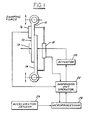
- Figure 1 is a schematic of an adjustable suspension unit and control system suitable for use together according to the present invention.
- Figure 2 is a perspective drawing of a motor vehicle incorporating the present system. This figure shows the various components of a system embodying the present invention.
- Figure 3 is an elevation of an adjustable suspension unit suitable for use with the present invention.
- Figure 4 is a partially cut-away view of the suspension unit shown in Figure 3.
- Figure 5 is a partial cross section of the suspension unit shown in Figure 4, taken along the line 5-5 of Figure 4.
- Figure 6 is a cross sectional view of a second type of adjustable damper suitable for use according to the present invention.
- Figure 7 is a cross sectional view of the damper shown in Figure 6, taken along the line 7-7 of Figure 6.
- Figure 8 is a logic flow block diagram in accordance with an embodiment of this invention.
- Figure 9 is a second logic flow block diagram in accordance with an embodiment of this invention.
- As shown in Figures 1 and 2, a control system according to the present invention is intended for use with an adjustable suspension unit having adjustable damping capability and used in an automotive vehicle. Those skilled in the art will appreciate in view of this disclosure that the present system could be employed with any wheeled land vehicle. As shown particularly in Figure 1,
adjustable suspension unit 10 comprises aportion 12 which is to be attached to a vehicle body and aportion 14 attached to a portion of the suspension which is more closely connected with the wheel and tire assembly. As shown in Figure 1, dampingsection 13 lies betweenportions adjustable suspension unit 10. Dampingsection 13 preferably comprises a sliding friction damping device such as those shown in Figures 3, 4, 5, 6 and 7, or may preferably comprise a hydraulic adjustable damping unit or other type of adjustable damping unit.Force sensor 16 is attached toportion 12 of the adjustable dampingunit 10. The force sensor may comprise a piezoelectric device or load cell, or other types of force sensors known to those skilled in the art and suggested by this disclosure. Those skilled in the art will appreciate in view of this disclosure that other locations may be employed for mounting the force sensor. In any event, the purpose of the force sensor is to measure the amount of damping force developed byadjustable suspension unit 10 and to transmit this information to the microprocessor and to the suspension unit operator. - The movement of
portions adjustable suspension unit 10 with respect to each other is detected bymotion sensor 18. This sensor may be constructed according to the several methods known to those skilled in the art and suggested by this disclosure. For example, the sensor may comprise a Hall Effect sensor such as those currently employed in some automotive vehicles, or the sensor may preferably may comprise a linear variable differential transformer (LVDT), or other types of sensors known to those skilled in the art and suggested by this disclosure. In any event,motion sensor 18 furnishes the present control system with information regarding the motion of the two portions ofadjustable suspension unit 10 with respect to each other. This information tells the control system at any given instance whether the adjustable suspension unit is moving in a jounce direction, i.e., in a direction wherein its length is decreasing, or in a rebound direction, i.e., in a direction wherein its length is increasing.Sensor 18 also discloses to the control system the precise position ofsuspension unit 10 in terms of its fully-extended, full-contracted states. This information is important because the present control system is intended to control the damping force generated byadjustable suspension unit 10 according to the particular stroke of the cycle in which the adjustable suspension unit is operating. - For the purposes of this document,
adjustable suspension unit 10 is considered to operate in a cycle. The cycle has two strokes. The first stroke, herein referred to as a rebound stroke, describes the motion of the adjustable suspension unit when its length is increasing. The second stroke, herein referred to as the jounce stroke, describes the motion of the adjustable suspension unit when its length is decreasing. It is understood that the adjustable suspension unit is attached at one end to one or more wheel and tire assemblies shown at 28 in Figure 2 as well as being attached to the body of the vehicle at the other end of the suspension unit. - As further shown in Figure 1, a system according to the present invention may comprise
actuator 20,suspension unit operator 22,microprocessor 24, andacceleration sensor 26. -
Actuator 20 functions to control the force developed byadjustable suspension unit 10. In the case of the suspension units described herein, this control results from the adjustment, by the actuator, of a sliding friction element contained within the adjustable suspension unit. Two types of sliding friction elements are shown in Figures 4-7 herein. -
Suspension unit operator 22 receives inputs fromforce sensor 16,motion sensor 18 andmicroprocessor 24. -
Microprocessor 24 outputs to suspension unit operator 22 a desired force signal.Suspension operator 22, knowing the measured force being generated by the adjustable suspension unit at any time by virtue of the signals fromforce sensor 16, then outputs the signal to actuator 20 to direct the actuator to adjust the damping force produced byadjustable suspension unit 10. -
Microprocessor 24 may receive various inputs fromaccleration sensor 26. For example,acceleration sensor 26 may be arranged to provide an input tomicroprocessor 24 relating to turning of the vehicle, or brake operation of the vehicle, or operation of the vehicle throttle, or vertical motion of the vehicle, or other inputs. Those skilled in the art will appreciate in view of this disclosure, therefore, thatacceleration sensor 26 could comprise a variety of sensors such as an accelerometer, a brake sensor such as a pressure sensor or electronic switch associated with the brake system of the vehicle, or other types of sensors such as a throttle position sensor included in a throttle mechanism operatively connected with the vehicle power plant. The steering sensor and associated control system disclosed in U.S. patent 4,621,833, which is hereby incorporated by reference herein, comprises yet another type of sensor useful for predicting lateral acceleration in a vehicle - Those skilled in the art will appreciate in view of this disclosure that
microprocessor 24 and its peripheral equipment could be structured according to several different architectures. In a preferred embodiment, however,microprocessor 24 is configured so that a control program is sequentially read for each unit command from a read-only memory (ROM) which stores preset control programs. Unit commands are executed by a central processing unit (CPU). The microprocessor integrally includes an input-output control circuit (I/O) for exchanging data with external devices and a random access memory (RAM) for temporarily holding data while the data are being processed. - As shown in Figure 2, a
vehicle including body 21 and four wheel andtire assemblies 28 hasadjustable suspension units 10 mounted generally between the wheel and tire assemblies and the vehicle body. A MacPherson strut suspension is illustrated at the front of the vehicle, whereas a Hotchkiss drive is shown at the rear. Those skilled in the art will appreciate in view of this disclosure, however, that an adjustable suspension unit and control system according to the present invention could be employed with a vehicle in a variety of suspension configurations, it being understood that those shown in Figure 2 are merely exemplary of the class of suspensions useful for practicing the present invention. - Figure 2 shows
microprocessor 24 mounted in the rear of the vehicle. The microprocessor enclosure also includessuspension unit operator 22. Those skilled in the art will appreciate in view of this disclosure however, thatmicroprocessor 24 andsuspension unit operator 22 could be integrated with an engine control computer, or any other type of on-board computer system within the vehicle. Moreover, multiple suspension unit operators may be employed so as to independently control each suspension unit with a unique operator. - As shown in Figure 2, wheel and
tire assemblies 28 are connected by means ofsuspensions 23 toadjustable suspension units 10. Although four adjustable suspension units are shown on the vehicle in Figure 2, it will be appreciated in view of this disclosure that adjustable units could be used at fewer than four locations in the vehicle. For example, if it is determined that a particular vehicle is particularly prone to fore and aft pitching, but not to roll during cornering, it may be desirable to equip the vehicle with adjustable suspension units at only the front or the rear of the vehicle. - The system shown in Figure 2 is powered by the vehicle's battery, 30. As previously, a plurality of sensors is employed to provide the system with information it needs in order to operate
adjustable suspension units 10. Accordingly, steeringsensor 32 is shown. This sensor functions as described in U.S. patent 4,621,833 which was previously incorporated by reference into this document.Brake sensor 34 is also shown, as isspeed sensor 38. The brake, speed, and steering sensors may all be used for the purpose of detecting acceleration of the vehicle. For example,speed sensor 38 detects vehicle speed and the data therefrom may be manipulated bymicroprocessor 24 to calculate vehicle velocity and acceleration.Brake sensor 34 detects operation of the vehicle's brake system and therefore will detect linear acceleration (or deceleration) of the vehicle due to application of the brakes.Throttle position sensor 40 may also be used to detect acceleration because application of the throttle will normally cause the vehicle's speed to increase.Steering sensor 32 may be used to predict lateral acceleration of the vehicle, because movement of the steering wheel will almost always precede the lateral acceleration occasioned by a subsequent turn. - A single accelerometer, 36, is shown as being mounted in the front of the vehicle in the approximate vicinity of the engine compartment. It could be understood that multiple accelerometers could be employed according to the present inventuion with one or more accelerometers at the front of the vehicle and one or more accelerometers at the rear of the vehicle. If desired, an accelerometer could be positioned adjacent to each
adjustable suspension unit 10. Alternatively, sensors could be deployed at the right and left sides (i.e., on the passenger and driver sides of the vehicle) to allow detection of body roll. It will be appreciated in view of this disclosure that the previously described accelerometers could be employed to detect acceleration in several mutually perpendicular planes such as laterally, longitudinally, or vertically. - As shown in Figures 3-5, one type of adjustable suspension unit suitable for use according to the present invention is of the rotary type. Although rotary friction dampers were used in automobiles many years ago, such dampers were unreliable because the force characteristics of the damper could not be regulated accurately. As a result, the damping characteristics were unreliable. As shown in Figure 3,
adjustable suspension unit 10 is mounted tobody 21 of the vehicle.Housing 48 of the adjustable suspension unit is attached to the body by means of a bracket or other conventional attaching techniques known to those skilled in the art.Adjustable suspension unit 10 is connected to the balance of the suspension according to any of several well known constructions by means oflink 44 which is attached topitman arm 42. The pitman arm is rigidly attached torotatable shaft 46 which is pivoted withinhousing 48. For this purpose, bearing 47 is provided at one end ofrotatable shaft 46. The opposite end ofrotatable shaft 46 is pivoted within plunger 54 (See Figure 4).Rotatable shaft 46 has a plurality ofrotors 50 keyed thereto. Figure 5 showsrotors 50 and this keying feature in greater detail.Rotors 50 rotate withrotatable shaft 46 asrotatable shaft 46 is driven bypitman arm 42, link 44 and the balance of the suspension attached to these components. - A plurality of
stators 52 is interleaved withrotors 50.Stator plates 52 are non-rotatably mounted withinouter housing 48.Stator plates 52 are urged to clampingly engagerotor plates 50 byplunger 54 so that rotation ofrotatable shaft 46 androtor plates 50 is thereby resisted. As a result,adjustable suspension unit 10 resists jounce and rebound motion of the suspension transmitted bylink 44 topitman arm 42. The measured amount of resistance to suspension motion (damping force) is fed intosuspension unit operator 22 by means offorce sensor 16. - The amount of damping force developed by
suspension unit 10 shown in Figure 4 is controlled byplunger 54 in conjunction withcrosslink 56,toggle link 58,lead screw 60, andtorque motor 62.Plunger 54 presses axially upon the interleaved stator and rotor plates so as to develop a normal force between the stator and rotor plates. Accordingly, the amount of friction acting between the rotor and stator plates and the resultant damping force developed by the suspension unit is controlled.Plunger 54 is loaded into the stator and rotor plate stack by means ofcrosslink 56, which is pivoted toouter housing 48 by means ofcrosslink pivot 57.Crosslink 56 is connected to a driving mechanism comprisinglead screw 60 andtorque motor 62 by means oftoggle link 58.Toggle link 58 has a pivot at either end allowinglead screw 60 andtorque motor 62 to move thecrosslink 56 in and out so as to either clamp tighter or more loosely plunger 54 and thereby, the stator and rotor stack. Leadscrew 60 andtorque motor 62 advantageously control the adjustable suspension unit because only very small displacements ofplunger 54 are needed to change the frictional force developed between the stator and rotor plates. This allows very high amplification of the actuator force with minimum actuator displacement. Thus, a small torque motor and lead screw assembly may be used while at the same time maintaining a high frequency response. Accordingly, the relationship between the force developed by the adjustable suspension unit and the electrical control signal is linear. The damping force developed by the adjustable suspension is therefore linearly related to the sliding frictional force through the coefficient of friction. Because the motor torque produced by the torque motor for small displacements is linearly proportional to the input current, the force produced by the damper is proportional to the current driving the motor. As a result, the frequency response of the suspension unit is limited primarily by the speed with which the current can be changed in the motor. Because this current can be changed very rapidly a suspension unit according to the principles described herein can have very fast response characteristics. In addition, the damping force developed by a suspension unit operated according to the principles described herein is independent of velocity of the suspension unit's motion in the jounce and rebound directions. A damper operated according to the present scheme can generate its maximum force at zero suspension velocity or at maximum suspension velocity or at any intermediate velocity. Because the damping is adjustable, moreover, the damper can be manipulated to provide zero damping if required. - A second embodiment of a damper useful for practicing the present invention is shown in Figures 6 and 7. In this embodiment,
piston rod 66 is attached tovehicle body 21. The lower end ofsuspension unit 10, includingcylindrical tube 71, is attached tosuspension 23 of the vehicle. Thus, as the suspension and attached wheel andtire assembly 28 moves through the jounce and rebound strokes,adjustable suspension unit 10 will be caused to contract and expand in length. This contraction and expansion in length is accompanied by the sliding of a plurality ofsemi-circular segments 68 uponinner surface 72 ofcylindrical tube 71. This sliding motion ofsemi-circular segments 68 dissipates energy in the manner of the rotational sliding of the rotors and stators of the previous embodiment. -
Semi-circular segments 68 are maintained in contact with theinner surface 72 ofcylindrical tube 71 by means ofwedge 74, shown in Figures 6 and 7.Wedge 74 is preloaded intosemi-circular segments 68 with the assistance of a plurality ofbearings 76 which are interposed between the semi-circular segments andwedge 74.Wedge 74 is driven bylead screw 60 which is operatively attached totorque motor 62. Leadscrew 60 is rotated bytorque motor 62 and the threads of the lead screw, which mate with threads formed upon an inner surface of the wedge, cause the wedge to be positioned more tightly or less tightly againstbearings 76 as the lead screw is rotated. As a result,semi-circular segments 68 are caused to be positioned so as to develop greater or lesser amounts of force between the semi-circular segments and theinner surface 72 ofcylindrical tube 70. In this manner, the damping force produced by the adjustable suspension unit is adjustable.Torque motor 62 is operated by means ofelectrical leads 64 which pass out of the adjustable suspension unit through one end ofpiston rod 66 and connect withsuspension operator 22. - Those skilled in the art will appreciate in view of this disclosure that other types of motors could be employed for the purpose of operating a shock absorber according to the present invention. For example, other types of hydraulic or electrical motors or other mechanical or electromechanical or hydraulic devices could be employed for the purpose of changing damping in the manner described herein. Further, those skilled in the art will appreciate in view of this disclosure that hydraulic or pneumatic damping devices could be employed according to the present invention, provided such hydraulic and pneumatic devices possess sufficient response characteristics in order to be compatible with the present system.
- As noted previously, a control system according to the description herein may be operated to either eliminate completely or reduce objectionable roll motion and other undesirable motions of a vehicle body. Such motions are encountered, for example, when the vehicle body "rolls over" during cornering. In this context, the term "roll over" does not mean literally that the vehicle's wheels leave the ground and vehicle rolls upon its side or roof, but rather "roll over" means, in the traditional automotive sense, that the body is caused, for a moment, to leave its normal riding attitude and to objectionably lift up on one side or the other. This objectionable body motion may also occur during braking operation, which is frequently accompanied by lifting of the rear end of the vehicle and lowering the front of the vehicle. Acceleration, on the other hand, may produce an objectionable lowering of the rear end of the vehicle and raising of the front end of the vehicle. The final type of objectionable motion which the present invention is intended to either reduce or eliminate, is vertical oscillation of the body as a result of road surface inputs.
- It has been found that the wheel and tire assemblies of a vehicle traversing a flat, level, and nominally smooth roadway will oscillate vertically (i.e., in the jounce and rebound directions) at a frequency of approximately 13 Hz. This oscillation of the wheel and tire assemblies will occur no matter how smooth the road surface appears to an unaided eye. The vehicle body, on the other hand, has a natural frequency of vibration of approximately 1.4 Hz, falling in a range of observed natural frequencies running from approximately 0.9 Hz to 1.8 Hz. Because the natural frequency of the body is approximately one order of magnitude less than the frequency of oscillation of the wheel and tire assemblies, the present invention can be used to impart some of the energy available in the oscillating wheel and tire assemblies to control the attitude of the body without causing the body to vibrate excessively. Accordingly, "pump-up" and "pump-down" routines are disclosed for controlling the attitude of the vehicle body by means of the present invention. As previously noted, the suspension of a vehicle described herein, including an adjustable suspension unit having variable damping capability, operates in a cycle comprising jounce and rebound strokes. Accordingly, if it is desired to raise that portion of the vehicle's body attached to a given suspension unit, the suspension unit will be controlled so that the suspension unit is set to achieve a greater degree of damping when the wheel and tire assembly and its associated suspension unit are moving in the jounce direction, whereas the suspension unit will be adjusted to achieve a lesser degree of damping when the wheel and tire assembly and associated suspension components are moving in the rebound direction. This is called "pump-on". Conversely, "pump-down" occurs when it is desired to move either the entire body, or only one side or end thereof in a downward, or, to apply a downwardly directed force to the body. In the case of pump-down operation, the adjustable suspension unit will be set to provide a lesser degree of damping when the suspension unit and wheel and tire assembly and the remainder of the suspension are moving in the jounce direction, but the suspension unit will be adjusted to provide maximum or at least a greater degree of damping when the wheel and tire assembly and suspension unit and the remainder of the suspension are moving in the rebound direction.
- Referring now to Figure 8, a simplified logic flow diagram for the operation of the control system of the present invention is shown. After
block 78, the start of the pump-up/pump-down routine, the computer transfers to block 80 wherein it asks whether pump-up or pump-down is required bymicroprocessor 24. - In the event that pump-up is required the computer transfers to block 82 wherein the velocity of
suspension unit 10 in either the jounce or rebound directions is determined. In the event that thesuspension unit 10 is moving in the rebound direction, the computer transfers to block 84 and sets the force output command tosuspension unit operator 22 at a zero or near zero level. In the event, however, thatsuspension unit 10 is moving in the jounce direction, the computer transfers to block 86 and determines an appropriate force to be developed by the damper. The desired force output information is transferred atblock 88 toactuator assembly 20 viasuspension unit operator 22. The computer then returns atblock 90 to startblock 78. In similar fashion, in the event that a pump-down is being requested bymicroprocessor 24, the computer transfers atblock 80 to block 92 wherein a question is asked about the velocity ofsuspension unit 10. In the event thatsuspension unit 10 is moving in the jounce direction, the force of the damper atblock 94 is set at zero or near zero, and an appropriate force command is then output to actuator 20 viasuspension operator 22 atblock 88. In the event, however, thatsuspension unit 10 is moving in the rebound direction, the computer will, atblock 96, set the damper force at some value greater than zero and a signal corresponding to this value will be outputted toactuator 20 viasuspension unit operator 22 atblock 88. - In the event that a vehicle equipped with the system described herein is turned in either the right or left directions, steering
sensor 32 and associated software will detect incipient lateral acceleration. If, for example the vehicle is making a left turn, which would normally cause the body to roll over to the right, the adjustable suspension units on the right side of the vehicle will be given a pump-up command, while the units on the left side of the vehicle will be given a pump-down command. Operation of the adjustable suspension units in this manner will counteract the roll of the body. In this example, the suspension units are controlled in response to detected incipient lateral acceleration. In similar fashion, should the driver of the vehicle apply the brakes, the suspension unit in the front of the vehicle can be given a pump-up command while those in the rear are given a pump-down command. Once again, this operation of the adjustable suspension units will tend to maintain the body at a level attitude. In this example, the suspension units are controlled in response to either incipient linear acceleration, or actual linear acceleration. Accordingly, the method and system described in Figure 8 comprises means for detecting vertical motion of the body with respect to a horizontal global reference plane and adjusting the force developed by the suspension units according to the particular stroke of the cycle which each suspension unit is operating, so that the suspension units will assert a net force upon the body in the direction tending to resist vertical motion of the body. In this manner, the force imposed upon the vehicle's body by the suspension unit is modulated according to the particular stroke the suspension unit is operating in, so that the suspension unit will exert a net force upon the vehicle's body in the desired direction, either upwardly or downwardly. The suspension unit thus exerts a net force upon the vehicle's body in only one direction, because although the individual forces exerted by the suspension unit in the jounce and rebound directions will tend to cancel each other, these forces will not be equal, and as a consequence, the sum of the forces will have an absolute value greater than zero. - It has been found that setting the magnitude of the force developed by the adjustable suspension unit proportional to the vertical velocity of the body with respect to a horizontal global reference plane produces an acceptable vehicle ride characteristic. This has been implemented in a "sky hook" method.
- Figure 9 discloses a sky hook method for operation of a system according to the present invention. Beginning at block 106, the start block, the computer transfers to block 108 wherein the computer ascertains with the help of the previously described sensors, whether the vehicle's body is moving relative to a horizontal reference plane. For this purpose, the sensors may include an accelerometer, or a high frequency ranging device such as a laser device, a radar, a microwave device, or other known devices. In the event that the body is not moving vertically above a predetermined threshold velocity the computer returns at
block 110 to the start block. In the event, however, that the body is moving above a threshold velocity in a vertical direction, the computer asks at block 112 whether the body is moving down. In the event that the body is moving down, the pump-up subroutine is selected atblock 114. This subroutine may be precisely that shown for pump-up in Figure 8, or a modified form of the subroutine. In any event, however, output of the adjustable suspension unit desired damping force signal to actuator 20 atblock 116 is done as before. Having done this, the computer transfers to block 118 to the start block. In the event that the body is moving up, the computer initiates the pump-down subroutine at block 120 and outputs a new force signal to the actuator atblock 122. In this manner, the vehicle body can be maintained at a level attitude, and the vehicle will be allowed to drive down a road without having unnecessarily harsh vertical body motion due either to inputs from the wheel and tire assemblies or from road surface imperfections. In any event, the magnitude of the desired damping force is calculated by the computer in the following manner. First, the computer integrates signals from the accelerometer or accelerometers in order to calculate the vehicle's vertical velocity. This calculated velocity is then transformed into a desired damping force signal. - The present invention provides a beneficial system and method for operating a suspension unit having adjustable damping capability because the present system is able to determine the particular stroke of the cycle which the suspension unit is operating, and the system is further able to both measure and to adjust the force developed by the suspension unit according to the stroke the unit is operating in so that the suspension unit will exert a net force upon the vehicle body in a desired direction.
- As used herein, the term "body" refers to a conventional automotive body, or to a conventional automotive body and chassis combination.
- Various modifications and variations will no doubt occur to those skilled in the various arts to which this invention pertains. For example, the particular sensors used in conjunction with the disclosed system may be varied from those disclosed within. Further, the suspension unit may comprise active or passive hydraulic, pneumatic, or electrical units in addition to those disclosed herein. These and all variations which basically rely on the teachings through which this disclosure has advanced the art are properly considered within the scope of this invention as defined by the appended claims.
Claims (16)
1. A suspension system for a motor vehicle having a body and road wheels supporting said body, with said road wheels being connected to said body by said suspension system, said suspension system comprising, an adjustable suspension unit (10) comprising a damping device (13) and adjustment means (12,14) for adjusting the damping force produced by said damping device in response to a control signal, sensor means (26) for predicting acceleration of said vehicle, and a control system (20,22,24) operatively connected to said adjustment means for controlling the damping of said adjustable suspension unit in response to a predicted acceleration signal from said sensor means so that said suspension unit will resist roll of said body resulting from said acceleration, said control system comprising means (20) for modulating the force imposed upon said body by said suspension unit by controlling the force developed by said damping device according to the particular stroke of the cycle in which said suspension unit is operating, so that said suspension unit will exert a net force upon said body in a direction tending to resist roll of said body in response to said acceleration.
2. A suspension system according to Claim 1, wherein said sensor means for predicting acceleration of said vehicle comprises a sensor activated by operation of a braking system associated with said vehicle or a throttle mechanism operatively connected with a powerplant incorporated in said vehicle.
3. A suspension system according to Claim 1, wherein said sensor means for predicting acceleration of said vehicle comprises an accelerometer or a sensor operatively connected with a steering system incorporated in said vehicle.
4. A suspension system according to any one of Claim 1 to 3, further comprising means for measuring the magnitude of the force developed by said suspension unit.
5. A suspension system according to Claim 1, wherein said control system comprises means for determining the particular stroke of the cycle in which said suspension unit is operating, and means for controlling the force produced by said suspension unit during any particular stroke of said suspension unit such that said suspension unit will, if located on that side of said body tending to move downward during said roll movement, apply a net force in an upward direction against said body, whereas in the event that said suspension unit is located on that side of said body tending to move upward during said roll movement, said suspension unit will be controlled so as to apply a downwardly directed force against said body.
6. A suspension system according to Claim 5, wherein said means for determining the particular stroke of the cycle in which said suspension unit is operating comprises means for sensing relative motion of at least a portion of said suspension unit with respect to the body of said vehicle or means for sensing relative motion between two elements of said suspension unit.
7. A suspension system for a motor vehicle having a body and road wheels supporting said body, with said road wheels being connected to said body by said suspension system, said suspension system comprising an adjustable suspension unit comprising a damping device and adjustment means for adjusting the damping force produced by said damping device in response to a control signal, sensor means for detecting vertical motion of said body, and a control system operatively connected to said adjustment means for controlling the damping of said adjustable suspension unit in response to a vertical motion signal from said sensor means so that said suspension unit will resist vertical motion of said body, said control system comprising means for modulating the force imposed upon said body by said suspension unit by controlling the force developed by said damping device according to the particular stroke of the cycle in which said suspension unit is operating, so that said suspension unit will exert a net force upon said body in a direction tending to resist sensed vertical motion of said body.
8. An adjustable suspension according to Claim 7 said sensor means for detecting vertical motion of said body comprises an accelerometer or a radio frequency ranging device.
9. An adjustable suspension according to Claim 8, wherein said control system operates said adjusting means so as to modulate the force developed by said suspension unit according to the magnitude of the velocity of said body with respect to a horizontal global reference plane.
10. An adjustable suspension according to Claim 8, wherein said control system operates said adjusting means so as to modulate the force developed by said suspension unit according to the rate of acceleration of said body with respect to a horizontal global reference plane.
11. A method for operating a motor vehicle suspension unit having adjustable damping capability, where said vehicle has a body supported by road wheels connected to said body by said suspension, said method comprising the steps of detecting vertical motion of said body with respect to a horizontal global reference plane, and adjusting the force developed by said suspension unit according to the particular stroke of the cycle in which said suspension unit is operating, so that said suspension unit will exert a net force upon said body in a direction tending to resist vertical motion of said body.
12. A method according to Claim 11, further comprising the step of measuring the magnitude of the force developed by said suspension unit.
13. A method according to Claim 11 or 12, wherein said suspension unit is controlled such that when said body is moving in an upward direction said suspension unit will apply a downwardly directed net force against said body, whereas when said body is moving in a downward direction said suspension unit will apply an upwardly directed net force against said body.
14. A method according to any one of Claims 11 to 13, wherein the force developed by said suspension unit is proportional to the vertical velocity of said body with respect to a horizontal global reference plane.
15. A method according to Claim 13, wherein said suspension unit is operated so as to apply a downwardly directed force against said body by adjusting said suspension unit to produce a greater amount of force when a road wheel and tyre assembly operatively associated with said suspension unit is moving in a direction away from the body of said vehicle and a lesser amount of force when said road wheel and tyre are moving in a direction toward the body of said vehicle.
16. A method according to Claim 13, wherein said suspension unit is operated so as to apply an upwardly directed force against said body by adjusting said suspension unit to produce a lesser amount of force when a road wheel and tyre assembly operatively associated with said suspension unit is moving in a direction away from the body of said vehicle and a greater amount of force when said road wheel and tyre assembly is moving in a direction toward the body of said vehicle.
Applications Claiming Priority (2)
| Application Number | Priority Date | Filing Date | Title |
|---|---|---|---|
| US5174 | 1987-01-20 | ||
| US07/005,174 US4809179A (en) | 1987-01-20 | 1987-01-20 | Control system for motor vehicle suspension unit |
Publications (2)
| Publication Number | Publication Date |
|---|---|
| EP0279507A2 true EP0279507A2 (en) | 1988-08-24 |
| EP0279507A3 EP0279507A3 (en) | 1989-10-25 |
Family
ID=21714543
Family Applications (1)
| Application Number | Title | Priority Date | Filing Date |
|---|---|---|---|
| EP88300286A Withdrawn EP0279507A3 (en) | 1987-01-20 | 1988-01-14 | Control system for motor vehicle suspension unit |
Country Status (4)
| Country | Link |
|---|---|
| US (1) | US4809179A (en) |
| EP (1) | EP0279507A3 (en) |
| JP (1) | JPS63192605A (en) |
| CA (1) | CA1285005C (en) |
Cited By (7)
| Publication number | Priority date | Publication date | Assignee | Title |
|---|---|---|---|---|
| EP0382479A1 (en) * | 1989-02-10 | 1990-08-16 | Lord Corporation | Method of operating a vibration attenuating system having semi-active damper means |
| EP0382480A1 (en) * | 1989-02-10 | 1990-08-16 | Lord Corporation | Vibration attenuating method utilizing continuously variable semiactive damper |
| EP0403803A1 (en) * | 1989-06-20 | 1990-12-27 | AUGUST BILSTEIN GMBH & CO. KG | Semi-active suspension |
| EP1252032A4 (en) * | 2000-12-07 | 2004-06-09 | Visteon Global Tech Inc | Suspension system for a vehicle |
| WO2014064501A1 (en) * | 2012-10-23 | 2014-05-01 | Toyota Jidosha Kabushiki Kaisha | Suspension control system and method of controlling suspension device |
| EP3074250A4 (en) * | 2013-11-29 | 2017-07-26 | Bae Systems Hägglunds Aktiebolag | Nose-dive reducing suspension lock arrangement for motor vehicle |
| US10125841B2 (en) | 2010-07-05 | 2018-11-13 | Fluid Ride, Ltd. | Suspension strut for a vehicle |
Families Citing this family (57)
| Publication number | Priority date | Publication date | Assignee | Title |
|---|---|---|---|---|
| US5144558A (en) * | 1986-06-13 | 1992-09-01 | Nissan Motor Company, Limited | Actively controlled automotive suspension system with adjustable rolling-stability and/or pitching-stability |
| US5358305A (en) * | 1987-08-13 | 1994-10-25 | Nissan Motor Co., Ltd. | Suspension system for automotive vehicle or the like |
| DE3816166C2 (en) * | 1988-05-11 | 1996-06-20 | Bosch Gmbh Robert | Agricultural tractor with attached implement |
| JPH02142942A (en) * | 1988-11-25 | 1990-06-01 | Atsugi Unisia Corp | hydraulic shock absorber |
| US4979595A (en) * | 1989-02-14 | 1990-12-25 | Paton H N | Fluid actuated friction damper |
| US4981309A (en) * | 1989-08-31 | 1991-01-01 | Bose Corporation | Electromechanical transducing along a path |
| JPH03189218A (en) * | 1989-12-19 | 1991-08-19 | Mitsubishi Electric Corp | Suspension control device |
| US5031934A (en) * | 1990-03-30 | 1991-07-16 | Ford Motor Company | Vehicular suspension position sensor and method of calibration |
| US5097419A (en) * | 1990-06-08 | 1992-03-17 | Monroe Auto Equipment Company | Method and apparatus for dynamic leveling |
| US5308938A (en) * | 1990-07-18 | 1994-05-03 | Otis Elevator Company | Elevator active suspension system |
| US5294757A (en) * | 1990-07-18 | 1994-03-15 | Otis Elevator Company | Active vibration control system for an elevator, which reduces horizontal and rotational forces acting on the car |
| US5321217A (en) * | 1990-07-18 | 1994-06-14 | Otis Elevator Company | Apparatus and method for controlling an elevator horizontal suspension |
| US5322144A (en) * | 1990-07-18 | 1994-06-21 | Otis Elevator Company | Active control of elevator platform |
| US5400872A (en) * | 1990-07-18 | 1995-03-28 | Otis Elevator Company | Counteracting horizontal accelerations on an elevator car |
| JP2756208B2 (en) * | 1991-03-13 | 1998-05-25 | オーチス エレベータ カンパニー | Horizontal deviation correction device for elevator cars running vertically |
| JP2756207B2 (en) * | 1991-03-13 | 1998-05-25 | オーチス エレベータ カンパニー | Method and apparatus for measuring horizontal deviation of an elevator car on a vertical shaft rail |
| US5434782A (en) * | 1991-05-20 | 1995-07-18 | General Motors Corporation | Suspension system state observer |
| CA2072240C (en) * | 1991-07-16 | 1998-05-05 | Clement A. Skalski | Elevator horizontal suspensions and controls |
| US5490068A (en) * | 1991-07-30 | 1996-02-06 | Atsugi Unisia Corporation | Suspension control system for automotive vehicle including apparatus for controlling shock absorber damping force coefficient |
| ZA927572B (en) * | 1991-10-24 | 1993-04-16 | Otis Elevator Co | Elevator ride quality. |
| US5510985A (en) * | 1992-01-05 | 1996-04-23 | Unisia Jecs Corporation | System for controlling damping force characteristic of shock absorber of vehicle |
| US5367459A (en) * | 1992-02-10 | 1994-11-22 | Trw Inc. | Apparatus for controlling dampers in a vehicle suspension system |
| US6259982B1 (en) * | 1993-02-02 | 2001-07-10 | Trw Inc. | Method and apparatus for controlling an active suspension system |
| US6032770A (en) * | 1993-04-12 | 2000-03-07 | Raytheon Company | Low force actuator for suspension control |
| US5610575A (en) * | 1994-08-25 | 1997-03-11 | Automotive Systems Laboratory, Inc. | Method and system for detecting vehicle roll-over |
| US5696677A (en) * | 1995-03-27 | 1997-12-09 | General Motors Corporation | Vehicle chassis control |
| US5682980A (en) * | 1996-02-06 | 1997-11-04 | Monroe Auto Equipment Company | Active suspension system |
| DE19811350C2 (en) * | 1997-03-19 | 2001-08-30 | Honda Motor Co Ltd | Tire contact load control system |
| KR100251805B1 (en) * | 1997-04-03 | 2000-04-15 | 밍루 | Control Method of Vehicle Suspension |
| US5979218A (en) * | 1997-11-12 | 1999-11-09 | Chrysler Corporation | Strut mount transducer |
| US6418360B1 (en) * | 1999-01-08 | 2002-07-09 | Shockware | Sensor structure for measuring vehicle suspension related information |
| US6196327B1 (en) | 1999-04-01 | 2001-03-06 | Case Corporation | EDC draft force based ride controller |
| US6691649B2 (en) | 2000-07-19 | 2004-02-17 | Bombardier-Rotax Gmbh | Fuel injection system for a two-stroke engine |
| US6988599B2 (en) | 2000-12-07 | 2006-01-24 | Visteon Global Technologies, Inc. | Compressible fluid strut |
| US6842684B1 (en) * | 2003-09-17 | 2005-01-11 | General Motors Corporation | Methods and apparatus for controlling a brake system |
| DE102005026047A1 (en) * | 2005-06-03 | 2006-12-14 | Benteler Automobiltechnik Gmbh | Suspension, |
| WO2008088736A2 (en) * | 2007-01-16 | 2008-07-24 | Charles Hampton Perry | Machine for augmentation, storage, and conservation of vehicle motive energy |
| EP2577027A2 (en) | 2010-06-03 | 2013-04-10 | Polaris Industries Inc. | Electronic throttle control |
| US9574582B2 (en) | 2012-04-23 | 2017-02-21 | Fluid Ride, Ltd. | Hydraulic pump system and method of operation |
| US9205717B2 (en) | 2012-11-07 | 2015-12-08 | Polaris Industries Inc. | Vehicle having suspension with continuous damping control |
| US10427483B1 (en) | 2013-04-10 | 2019-10-01 | Ala Holdings, Llc | Adjustable ride height, vehicle, system and kit |
| US9150247B2 (en) | 2013-04-10 | 2015-10-06 | Aaron L. Aldrich | Adjustable ride height, vehicle, system and kit |
| US9552679B2 (en) * | 2013-10-17 | 2017-01-24 | Ford Global Technologies, Llc | System and method for vehicle damper monitoring |
| US9428242B2 (en) * | 2014-02-24 | 2016-08-30 | Harley-Davidson Motor Company Group, LLC | Variable ride height systems and methods |
| US10648554B2 (en) | 2014-09-02 | 2020-05-12 | Polaris Industries Inc. | Continuously variable transmission |
| WO2016069405A2 (en) | 2014-10-31 | 2016-05-06 | Polaris Industries Inc. | System and method for controlling a vehicle |
| CA3043481C (en) | 2016-11-18 | 2022-07-26 | Polaris Industries Inc. | Vehicle having adjustable suspension |
| US10358010B2 (en) | 2017-06-05 | 2019-07-23 | Tenneco Automotive Operating Company Inc. | Interlinked active suspension |
| US10406884B2 (en) | 2017-06-09 | 2019-09-10 | Polaris Industries Inc. | Adjustable vehicle suspension system |
| CN111836980A (en) | 2018-03-19 | 2020-10-27 | 北极星工业有限公司 | CVT |
| US11135887B2 (en) | 2018-10-19 | 2021-10-05 | Ala Holdings, Llc | Adjustable suspension mount system and method |
| US10987987B2 (en) | 2018-11-21 | 2021-04-27 | Polaris Industries Inc. | Vehicle having adjustable compression and rebound damping |
| US11479073B2 (en) * | 2020-03-05 | 2022-10-25 | GM Global Technology Operations LLC | Vehicle body roll reduction |
| CN120735865A (en) | 2020-05-20 | 2025-10-03 | 北极星工业有限公司 | System and method for adjustable suspension for off-road recreational vehicle |
| MX2022015902A (en) | 2020-07-17 | 2023-01-24 | Polaris Inc | Adjustable suspensions and vehicle operation for off-road recreational vehicles. |
| WO2022165160A1 (en) | 2021-01-29 | 2022-08-04 | Polaris Industries Inc. | Electronically-controlled continuously variable transmission for a utility vehicle |
| JP7281498B2 (en) * | 2021-03-22 | 2023-05-25 | 本田技研工業株式会社 | electric suspension device |
Family Cites Families (33)
| Publication number | Priority date | Publication date | Assignee | Title |
|---|---|---|---|---|
| US375759A (en) * | 1888-01-03 | Boom-grip | ||
| US875759A (en) * | 1907-07-10 | 1908-01-07 | Lawrence Whitcomb | Shock-absorber. |
| US1671658A (en) * | 1926-12-03 | 1928-05-29 | Richard H Travers | Shock absorber |
| US3052458A (en) * | 1959-11-17 | 1962-09-04 | Schnitzer Emanuel | Band pass shock strut |
| GB1267815A (en) * | 1968-07-29 | 1972-03-22 | Lucas Industries Ltd | Road vehicle suspension systems |
| US3606365A (en) * | 1969-11-03 | 1971-09-20 | Budd Co | Active suspension system for a vehicle |
| US3861696A (en) * | 1972-06-01 | 1975-01-21 | Bofors Ab | Device for damping rocking movements occurring in a chassis |
| JPS521770B2 (en) * | 1973-07-04 | 1977-01-18 | ||
| US3866724A (en) * | 1973-08-13 | 1975-02-18 | Harold S Hollnagel | Variable two-way shock absorber |
| JPS5143521A (en) * | 1974-10-14 | 1976-04-14 | Nissan Motor | Jidoshano kagensokujishataishiseiseigyosochi |
| US3990542A (en) * | 1974-12-16 | 1976-11-09 | Tyee Aircraft, Inc. | Linear motion arresting device |
| DE2911768C2 (en) * | 1979-03-26 | 1983-01-20 | F & O Electronic Systems GmbH & Co, 6901 Neckarsteinach | Adjustable shock absorbers, in particular for motor vehicles |
| JPS5660710A (en) * | 1979-10-19 | 1981-05-25 | Tokico Ltd | Car height adjuster |
| US4333668A (en) * | 1979-12-17 | 1982-06-08 | The Bendix Corporation | Electronic adaptive ride control system |
| DE3048532A1 (en) * | 1980-12-22 | 1982-07-22 | Pietzsch, Ludwig, Dr.-Ing., 7500 Karlsruhe | Variable friction damper for vehicle suspension - has electromagnetic damping brake excited by tachometer |
| JPS57126706A (en) * | 1981-01-30 | 1982-08-06 | Aisin Seiki Co Ltd | Car height regulator |
| JPS6034905U (en) * | 1983-08-19 | 1985-03-09 | 三菱自動車工業株式会社 | electronically controlled suspension |
| JPS6092915A (en) * | 1983-10-27 | 1985-05-24 | Nippon Denso Co Ltd | Car height control device |
| US4595072A (en) * | 1983-10-27 | 1986-06-17 | Daniel Barnea | Vehicle suspension system |
| JPS60128011A (en) * | 1983-12-12 | 1985-07-08 | Nissan Motor Co Ltd | Roll rigidity control equipment for vehicle |
| US4625992A (en) * | 1984-01-24 | 1986-12-02 | Mitsubishi Jidosha Kogyo Kabushiki Kaisha | Vehicle suspension apparatus |
| JPS60183211A (en) * | 1984-02-29 | 1985-09-18 | Nissan Motor Co Ltd | Suspension system for vehicle |
| DE3414258A1 (en) * | 1984-04-14 | 1985-10-24 | Robert Bosch Gmbh, 7000 Stuttgart | DEVICE FOR CONTROLLING THE SUSPENSION OF A VEHICLE I |
| DE3515014A1 (en) * | 1984-04-25 | 1985-10-31 | Mitsubishi Jidosha Kogyo K.K., Tokio/Tokyo | VEHICLE SUSPENSION |
| JPS6150817A (en) * | 1984-08-18 | 1986-03-13 | Toyota Motor Corp | Controller for damping force in shock absorber of variable damping force type |
| US4697237A (en) * | 1984-11-21 | 1987-09-29 | Mitsubishi Jidosha Kogyo Kabushiki Kaisha | Vehicle suspension apparatus |
| US4589676A (en) * | 1984-12-13 | 1986-05-20 | General Motors Corporation | Adaptive ride control for motor vehicle |
| JPS61163011A (en) * | 1985-01-14 | 1986-07-23 | Nissan Motor Co Ltd | Electronic control shock absorber |
| JPS61163009A (en) * | 1985-01-14 | 1986-07-23 | Toyota Motor Corp | Vehicle |
| US4722546A (en) * | 1985-01-18 | 1988-02-02 | Toyota Jidosha Kabushiki Kaisha | Rear suspension controller |
| DE3524862A1 (en) * | 1985-04-12 | 1986-10-30 | Robert Bosch Gmbh, 7000 Stuttgart | DEVICE FOR DAMPING MOTION PROCESSES |
| JPH07446B2 (en) * | 1985-10-26 | 1995-01-11 | トヨタ自動車株式会社 | Suspension controller |
| US4621833A (en) * | 1985-12-16 | 1986-11-11 | Ford Motor Company | Control system for multistable suspension unit |
-
1987
- 1987-01-20 US US07/005,174 patent/US4809179A/en not_active Expired - Lifetime
-
1988
- 1988-01-13 CA CA000556443A patent/CA1285005C/en not_active Expired - Lifetime
- 1988-01-14 EP EP88300286A patent/EP0279507A3/en not_active Withdrawn
- 1988-01-18 JP JP63008204A patent/JPS63192605A/en active Pending
Cited By (11)
| Publication number | Priority date | Publication date | Assignee | Title |
|---|---|---|---|---|
| EP0382479A1 (en) * | 1989-02-10 | 1990-08-16 | Lord Corporation | Method of operating a vibration attenuating system having semi-active damper means |
| EP0382480A1 (en) * | 1989-02-10 | 1990-08-16 | Lord Corporation | Vibration attenuating method utilizing continuously variable semiactive damper |
| EP0403803A1 (en) * | 1989-06-20 | 1990-12-27 | AUGUST BILSTEIN GMBH & CO. KG | Semi-active suspension |
| EP1252032A4 (en) * | 2000-12-07 | 2004-06-09 | Visteon Global Tech Inc | Suspension system for a vehicle |
| US6811167B2 (en) | 2000-12-07 | 2004-11-02 | Visteon Global Technologies, Inc. | Suspension system for a vehicle |
| US10125841B2 (en) | 2010-07-05 | 2018-11-13 | Fluid Ride, Ltd. | Suspension strut for a vehicle |
| WO2014064501A1 (en) * | 2012-10-23 | 2014-05-01 | Toyota Jidosha Kabushiki Kaisha | Suspension control system and method of controlling suspension device |
| US9180748B2 (en) | 2012-10-23 | 2015-11-10 | Toyota Jidosha Kabushiki Kaisha | Suspension control system and method of controlling suspension device |
| DE112013003144B4 (en) * | 2012-10-23 | 2017-06-29 | Toyota Jidosha Kabushiki Kaisha | Suspension control system and method of controlling a suspension device |
| EP3074250A4 (en) * | 2013-11-29 | 2017-07-26 | Bae Systems Hägglunds Aktiebolag | Nose-dive reducing suspension lock arrangement for motor vehicle |
| US10131386B2 (en) | 2013-11-29 | 2018-11-20 | BAE Systems Hägglunds Aktiebolag | Nose-dive reducing suspension lock arrangement for motor vehicle |
Also Published As
| Publication number | Publication date |
|---|---|
| US4809179A (en) | 1989-02-28 |
| JPS63192605A (en) | 1988-08-10 |
| EP0279507A3 (en) | 1989-10-25 |
| CA1285005C (en) | 1991-06-18 |
Similar Documents
| Publication | Publication Date | Title |
|---|---|---|
| US4809179A (en) | Control system for motor vehicle suspension unit | |
| EP0277788B1 (en) | Motor vehicle suspension with adjustable unit and control system therefor | |
| JP3059527U (en) | Active suspension | |
| EP0469051B1 (en) | Vehicle suspension system | |
| JP4070875B2 (en) | Suspension device having spring straightening device | |
| US5089966A (en) | Actively controlled automotive suspension system with improved damping characteristics | |
| US4909535A (en) | Vehicle suspension system, and method of operating same | |
| US5390121A (en) | Banded on-off control method for semi-active dampers | |
| US7788011B2 (en) | Braking and drive force control apparatus for a vehicle | |
| US5765115A (en) | Pneumatic tilt stabilization suspension system | |
| JPH0662052B2 (en) | Spring mechanism for wheel suspension | |
| WO1994001988A2 (en) | A vehicle suspension system | |
| JPH0585369B2 (en) | ||
| EP0599882A4 (en) | VEHICLE SUSPENSION. | |
| EP0217401A2 (en) | Suspension controller | |
| US4861067A (en) | Active vehicle suspension with composite control arm | |
| US7665585B2 (en) | Vehicle suspension system and method for operating | |
| EP3655268B1 (en) | A suspension provided with a load responsive device | |
| US11498383B2 (en) | Continuously variable rate fluid spring system for a vehicle, and method of operation | |
| JP2575485B2 (en) | Active suspension | |
| JP7265412B2 (en) | ELASTIC BUSH, SUSPENSION DEVICE, AND SUPPORT STRUCTURE FOR POWER TRANSMISSION MECHANISM | |
| JPH0612136B2 (en) | Elastic support device for cab | |
| JPS5923786A (en) | Shock absorber for motorcycle | |
| KR100693149B1 (en) | Semi-active suspension of the vehicle | |
| JPH1134628A (en) | Ground load control device |
Legal Events
| Date | Code | Title | Description |
|---|---|---|---|
| PUAI | Public reference made under article 153(3) epc to a published international application that has entered the european phase |
Free format text: ORIGINAL CODE: 0009012 |
|
| AK | Designated contracting states |
Kind code of ref document: A2 Designated state(s): DE FR GB |
|
| PUAL | Search report despatched |
Free format text: ORIGINAL CODE: 0009013 |
|
| AK | Designated contracting states |
Kind code of ref document: A3 Designated state(s): DE FR GB |
|
| 17P | Request for examination filed |
Effective date: 19900314 |
|
| 17Q | First examination report despatched |
Effective date: 19911010 |
|
| STAA | Information on the status of an ep patent application or granted ep patent |
Free format text: STATUS: THE APPLICATION HAS BEEN WITHDRAWN |
|
| 18W | Application withdrawn |
Withdrawal date: 19920418 |