EP0279224A1 - Method for photopolymerizing UV-curable materials - Google Patents
Method for photopolymerizing UV-curable materials Download PDFInfo
- Publication number
- EP0279224A1 EP0279224A1 EP88101041A EP88101041A EP0279224A1 EP 0279224 A1 EP0279224 A1 EP 0279224A1 EP 88101041 A EP88101041 A EP 88101041A EP 88101041 A EP88101041 A EP 88101041A EP 0279224 A1 EP0279224 A1 EP 0279224A1
- Authority
- EP
- European Patent Office
- Prior art keywords
- curing
- irradiation
- light
- curing material
- gap
- Prior art date
- Legal status (The legal status is an assumption and is not a legal conclusion. Google has not performed a legal analysis and makes no representation as to the accuracy of the status listed.)
- Granted
Links
Images
Classifications
-
- G—PHYSICS
- G02—OPTICS
- G02B—OPTICAL ELEMENTS, SYSTEMS OR APPARATUS
- G02B6/00—Light guides; Structural details of arrangements comprising light guides and other optical elements, e.g. couplings
- G02B6/24—Coupling light guides
- G02B6/36—Mechanical coupling means
- G02B6/38—Mechanical coupling means having fibre to fibre mating means
-
- G—PHYSICS
- G02—OPTICS
- G02B—OPTICAL ELEMENTS, SYSTEMS OR APPARATUS
- G02B5/00—Optical elements other than lenses
Definitions
- the invention relates to a method for curing UV-curing materials, in particular adhesives and lacquers, by irradiation with UV light.
- UV-curing adhesives and varnishes are used in the manufacture of optical components and in printed circuit board technology, especially conductive adhesives and conductive varnishes. These materials cure very quickly under intensive and even exposure to UV light, e.g. in less than 60 seconds, but always have a volume shrinkage that is within the limits of approx. 2.5 vol.% up to 10 vol.%. On the one hand, good adhesive strength is to be produced, but shrinking of the adhesive or lacquer layer, combined with cracking or blistering, with misplacement or warping or even with breakage of the component, is undesirable and should be avoided. This requires a high level of processing care.
- any cracks that degrade the visual appearance of the parts or reduce the conductivity can be repaired by adding new substance.
- a method of completely avoiding the loss of volume and the corresponding tensions is not yet known.
- the invention has for its object to eliminate the aforementioned disadvantages.
- the irradiation of the UV-curing material is controlled by an aperture such that - The irradiation with UV light begins at at least one point and the irradiated area is concentrically enlarged from this point to the outside or - The irradiation with UV light begins on at least one line and the entire surface of the UV-curing material is irradiated by a relative displacement between the material and the screen in at least one direction.
- the method is consequently designed such that, starting from at least one predetermined point or at least one predetermined line, corresponding to the reaction center or the reaction line, the photochemical reaction continues by moving a front of UV light in the direction of this front.
- the material shrinking during curing can draw liquid material from its not yet hardened environment or from a reservoir.
- a movable front of UV light is created by a variable or movable screen, the material of which is impermeable to UV light.
- a preferred embodiment of this invention is provided by using a perforated diaphragm with a variable diameter.
- the method envisages starting with a small aperture, whereby only a punctiform radiation is generated on the UV-curing material, and then opening the pinhole at a defined speed until the entire surface of the UV-curing material is irradiated by UV light .
- the second-mentioned procedure in claim 1 corresponds to the same inventive idea as the first. It assumes that the photochemical reaction begins on a line, the front of the UV light progressing here by displacing a gap or a partial cover relative to the surface of the UV-curing material.
- An extremely advantageous embodiment of the invention is realized through the use of a movable gap which is moved relative to the UV-curing material.
- the method carried out in this way ensures that a certain point or line of the UV-curing material is exposed by passing over the front limit of the gap in the direction of movement, remains exposed for a time and the exposure is ended after crossing the limit of the gap in the direction of movement.
- a partial cover can also be used as the gap, which at the beginning of the exposure releases only a narrow strip of the UV-curing material for exposure and is subsequently pulled down sideways until the entire surface of the UV-curing material is exposed.
- the defined progression of a front of UV light has an opposite flow of the still fluid subs dance and thus leads to a compensation for the otherwise occurring volume loss.
- the shrinkage in volume can either be completely compensated for or, if it is only of a minor extent, be taken into account from the start, so that the desired layer thicknesses can be set without errors.
- Another particularly advantageous embodiment of the invention provides that the mutual displacement between the movable gap and the UV-curing material takes place at a constant speed. This means that all areas of the UV-curing material have the same exposure time and therefore harden particularly evenly.
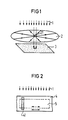
- a surface with UV-curing material 3 is to be exposed by UV light 1, controlled by a pinhole 2, for example an iris.
- the initially small opening of the aperture 21 leads to a correspondingly small point or circular exposure of the UV-curing material, so that a reaction center arises.
- the arrows indicated within the aperture 2 indicate that the aperture is slowly opened during the process until the entire surface of the UV-curing material 3 is sufficiently exposed. With this procedure, no uniform exposure time is achieved for the various locations of the UV-curing material.
- the essential thing, namely to avoid the loss of volume of the material is the concentric progressive circular front of the UV light on the UV-curing material causes. This defined movement of the front of the UV light creates an opposite flow of still liquid substance, which in this case is directed radially inwards towards the reaction center and thus compensates for the volume shrinkage that occurs during curing.
- FIG. 2 shows an area of UV-curing material 5 that is to be exposed by UV light 1.
- the aperture 4 is designed as a gap 41.
- the exposure of the UV-curing material begins on a predetermined side on a line and ensures a constant speed uniform exposure time of all points of the UV-curing material.
- a simple implementation of this version of the method is provided by a fixed UV light source, an underlying aperture in the form of a stationary gap and an underlying conveyor belt on which the components with the UV-curing layers are transported at a constant speed.
- the gap opening width or intensity of the UV light 1 can be set as a function of the material properties of the UV-curing adhesive or lacquer.
Abstract
Description
Die Erfindung betrifft ein Verfahren zum Aushärten von UV-härtenden Materialien, insbesondere von Klebern und Lacken, durch die Bestrahlung mit UV-Licht.The invention relates to a method for curing UV-curing materials, in particular adhesives and lacquers, by irradiation with UV light.
UV-härtende Kleber und Lacke werden bei der Fertigung von optischen Komponenten und in der Leiterplattentechnik, hier speziell Leitkleber und Leitlacke, eingesetzt. Diese Materialien härten unter intensiver und gleichmäßiger Bestrahlung mit UV-Licht sehr rasch aus, z.B. in weniger als 60 sec., weisen jedoch stets einen Volumenschwund auf, der in den Grenzen von ca. 2,5 Vol.-% bis zu 10 Vol.-% liegt. Einerseits soll eine gute Haftfestigkeit erzeugt werden, wobei jedoch ein Schrumpfen der Klebe- oder Lackschicht, verbunden mit Riß- oder Blasenbildung, mit Deplazierung oder Verwerfung oder sogar mit Bruch des Bauteiles, unerwünscht ist und vermieden werden sollte. Dies erfordert eine hohe Bearbeitungssorgfalt. Falls das Bauteil den während des Aushärtens in der Klebe- oder Lackschicht auftretenden Spannungen standhält, lassen sich eventuelle Risse, die das optische Aussehen der Teile verschlechtern bzw. die Leitfähigkeit herabsetzen, durch Zugabe neuer Substanz reparieren. Ein Verfahren, den Volumenschwund und die entsprechenden Spannungen gänzlich zu vermeiden, ist bisher nicht bekannt.UV-curing adhesives and varnishes are used in the manufacture of optical components and in printed circuit board technology, especially conductive adhesives and conductive varnishes. These materials cure very quickly under intensive and even exposure to UV light, e.g. in less than 60 seconds, but always have a volume shrinkage that is within the limits of approx. 2.5 vol.% up to 10 vol.%. On the one hand, good adhesive strength is to be produced, but shrinking of the adhesive or lacquer layer, combined with cracking or blistering, with misplacement or warping or even with breakage of the component, is undesirable and should be avoided. This requires a high level of processing care. If the component withstands the stresses that occur in the adhesive or lacquer layer during curing, any cracks that degrade the visual appearance of the parts or reduce the conductivity can be repaired by adding new substance. A method of completely avoiding the loss of volume and the corresponding tensions is not yet known.
In der heutigen Belichtungstechnik wird stets mit hohen UV-Intensitäten auf großen Flächen gearbeitet. Der Mechanismus des Aushärtens ist bei dieser gleichmäßigen und gleichzeitigen Bestrahlung der gesamten Fläche des UV-härtenden Materials jedoch zufällig und unkontrolliert. Die fotochemische Reaktion startet an vielen Stellen der Materialschicht, an sogenannten Reaktionszentren. Von diesen Zentren aus beginnt die Schrumpfung. Dadurch können Inhomogenitäten in der Klebe- oder Lackschicht entstehen, weil noch flüssige Materialanteile durch bereits ausgehärtete Schichten getrennt werden und somit kein Ausgleich des Volumenschwundes durch Ansaugen von flüssigem Material aus der Umgebung stattfinden kann. Dies führt nach dem Aushärten und Schrumpfen des flüssigen eingeschlossenen Materials zu unterschiedlichen Belastungen in der Klebe- oder Lackschicht und zu den obengenannten Fehlern.In today's exposure technology, high UV intensities are always used on large areas. The mechanism of curing is random and uncontrolled with this uniform and simultaneous irradiation of the entire surface of the UV-curing material. The photochemical reaction starts at many points in the material layer, at so-called reaction centers. The shrinkage begins from these centers. This can result in inhomogeneities in the adhesive or lacquer layer because liquid material parts are already present cured layers are separated and thus no compensation for the volume shrinkage by sucking in liquid material from the environment can take place. After curing and shrinking of the liquid enclosed material, this leads to different loads in the adhesive or lacquer layer and to the above-mentioned errors.
Der Erfindung liegt die Aufgabe zugrunde, die vorgenannten Nachteile zu beseitigen.The invention has for its object to eliminate the aforementioned disadvantages.
Diese Aufgabe wird erfindungsgemäß dadurch gelöst, daß die Bestrahlung des UV-härtenden Materials durch eine Blende derart gesteuert wird, daß
- die Bestrahlung mit UV-Licht an mindenstens einem Punkt beginnt und die bestrahlte Fläche konzentrisch von diesem Punkt nach außen hin vergrößert wird oder
- die Bestrahlung mit UV-Licht an mindestens einer Linie beginnt und die gesamte Fläche des UV-härtenden Materials, durch eine relative Verschiebung zwischen Material und Blende in mindenstens einer Richtung, bestrahlt wird.This object is achieved in that the irradiation of the UV-curing material is controlled by an aperture such that
- The irradiation with UV light begins at at least one point and the irradiated area is concentrically enlarged from this point to the outside or
- The irradiation with UV light begins on at least one line and the entire surface of the UV-curing material is irradiated by a relative displacement between the material and the screen in at least one direction.
Das Verfahren wird folglich so gestaltet, daß, ausgehend von mindestens einem vorbestimmten Punkt oder mindestens einer vorbestimmten Linie, entsprechend dem Reaktionszentrum oder der Reaktionslinie, die fotochemische Reaktion durch die Bewegung einer Front von UV-Licht in Richtung dieser Front weiterläuft. Das bei der Aushärtung schrumpfende Material kann aus seiner noch nicht ausgehärteten Umgebung oder aus einem Reservoir flüssiges Material nachziehen. Hierdurch wird das Schrumpfen der Klebung oder der Lackschicht weitestgehend vermieden, da es bei dieser Verfahrensweise nicht zu Einschlüssen von noch flüssigem Material kommt.
Eine bewegbare Front von UV-Licht wird durch eine veränderliche oder bewegbare Blende erzeugt, deren Material für UV-Licht undurchlässig ist.The method is consequently designed such that, starting from at least one predetermined point or at least one predetermined line, corresponding to the reaction center or the reaction line, the photochemical reaction continues by moving a front of UV light in the direction of this front. The material shrinking during curing can draw liquid material from its not yet hardened environment or from a reservoir. As a result, the shrinkage of the adhesive or the lacquer layer is largely avoided, since this procedure does not lead to inclusions of still liquid material.
A movable front of UV light is created by a variable or movable screen, the material of which is impermeable to UV light.
Die erstgenannte Verfahrensweise im Anspruch 1, die von einer punktförmigen Bestrahlung ausgeht, erzeugt eine kreis förmige Front von UV-Licht, die sich von dem Punkt als Reaktionszentrum in form von kontinuierlich oder in kleinen Stufen sich vergrößernden Kreisen konzentrisch nach außen hin ausbreitet.The first-mentioned procedure in claim 1, which starts from punctiform radiation, creates a circle shaped front of UV light, which concentrically spreads outwards from the point as a reaction center in the form of circles that enlarge continuously or in small steps.
Eine bevorzugte Ausgestaltung dieser Erfindung ist durch den Einsatz einer Lochblende mit veränderlichem Durchmesser gegeben. Das Verfahren sieht vor mit einer kleinen Blendenöffnung zu beginnen, wobei auf dem UV-härtenden Material nur eine punktförmige Bestrahlung erzeugt wird, und anschließend die Lochblende mit definierter Geschwindigkeit zu öffnen, bis die gesamte Fläche des UV-härtenden Materials von UV-Licht bestrahlt wird.A preferred embodiment of this invention is provided by using a perforated diaphragm with a variable diameter. The method envisages starting with a small aperture, whereby only a punctiform radiation is generated on the UV-curing material, and then opening the pinhole at a defined speed until the entire surface of the UV-curing material is irradiated by UV light .
Die zweitgenannte Verfahrensweise im Anspruch 1 entspricht der gleichen erfinderischen Idee wie die erstgenannte. Sie geht davon aus, daß die fotochemische Reaktion an einer Linie beginnt, wobei hier die Front des UV-Lichtes durch Verschiebung eines Spaltes oder einer partiellen Abdeckung relativ zu der Fläche des UV-härtenden Materiales fortschreitet.The second-mentioned procedure in claim 1 corresponds to the same inventive idea as the first. It assumes that the photochemical reaction begins on a line, the front of the UV light progressing here by displacing a gap or a partial cover relative to the surface of the UV-curing material.
Eine äußerst vorteilhafte Ausgestaltung der Erfindung wird durch den Einsatz eines bewegbaren Spaltes realisiert, der relativ zum UV-härtenden Material bewegt wird. Das derart durchgeführte Verfahren sorgt dafür, daß eine bestimmte Stelle oder Linie des UV-härtenden Materials durch Überfahren der in Bewegungsrichtung vorderen Grenze des Spaltes belichtet wird, eine Zeitlang belichtet bleibt und die Belichtung nach Überfahren der in Bewegungsrichtung hinteren Grenze des Spaltes beendet wird.An extremely advantageous embodiment of the invention is realized through the use of a movable gap which is moved relative to the UV-curing material. The method carried out in this way ensures that a certain point or line of the UV-curing material is exposed by passing over the front limit of the gap in the direction of movement, remains exposed for a time and the exposure is ended after crossing the limit of the gap in the direction of movement.
Genauso kann als Spalt auch eine partielle Abdeckung verwendet werden, die zu Anfang der Belichtung nur einen schmalen Streifen des UV-härtenden Materiales zur Belichtung freigibt und im Anschluß daran seitwärts heruntergezogen wird, bis die gesamte Fläche des UV-härtenden Materiales belichtet ist.In the same way, a partial cover can also be used as the gap, which at the beginning of the exposure releases only a narrow strip of the UV-curing material for exposure and is subsequently pulled down sideways until the entire surface of the UV-curing material is exposed.
Das definierte Fortschreiten einer Front von UV-Licht hat jeweils eine entgegengesetzte Strömung der noch flüssigen Subs tanz zur Folge und führt somit zu einem Ausgleich für den sonst auftretenden Volumenschwund. Der Volumenschwund entweder vollständig ausgeglichen werden oder, falls dieser nur geringfügiges Ausmaß hat, von Anfang an mit berücksichtigt werden, so daß gewünschte Schichtdicken fehlerfrei einstellbar sind.The defined progression of a front of UV light has an opposite flow of the still fluid subs dance and thus leads to a compensation for the otherwise occurring volume loss. The shrinkage in volume can either be completely compensated for or, if it is only of a minor extent, be taken into account from the start, so that the desired layer thicknesses can be set without errors.
Eine weitere besonders vorteilhafte Ausgestaltung der Erfindung sieht vor, daß die gegenseitige Verschiebung zwischen bewegbarem Spalt und UV-härtendem Material mit konstanter Geschwindigkeit abläuft. Dies führt dazu, daß alle Stellen des UV-härtenden Materials dieselbe Belichtungszeit haben und somit besonders gleichmäßig Aushärten.Another particularly advantageous embodiment of the invention provides that the mutual displacement between the movable gap and the UV-curing material takes place at a constant speed. This means that all areas of the UV-curing material have the same exposure time and therefore harden particularly evenly.
Die beiden Ausführungsbeispiele zeigen in stark vereinfachter schematischer Darstellung:
- Fig. 1 Belichtung einer Fläche von UV-
härtendem Material 3 mittels einerLochblende 2 mit veränderlichem Durchmesser, - Fig. 2 Belichtung einer Fläche von UV-härtendem Material mittels eines relativ dazu bewegbaren Spaltes 41.
- 1 exposure of a surface of UV-curing
material 3 by means of aperforated diaphragm 2 with a variable diameter, - 2 exposure of a surface of UV-curing material by means of a gap 41 which can be moved relative to it.
In Fig. 1 wird ersichtlich, daß eine Fläche mit UV-härtendem Material 3 durch UV-Licht 1, gesteuert durch eine Lochblende 2 z.B. eine Irisblende zu belichten ist. Die anfänglich kleine Öffnung der Blende 21 führt zu einer entsprechend kleinen punkt- oder kreisförmigen Belichtung des UV-härtenden Materials,
so daß ein Reaktionszentrum entsteht. Die innerhalb der Lochblende 2 angedeuteten Pfeile weisen daraufhin, daß die Blende während des Verfahrens langsam geöffnet wird, bis die gesamte Fläche des UV-härtenden Materials 3 ausreichend belichtet ist. Bei dieser Verfahrensweise wird keine einheitliche Belichtungszeit für die verschiedenen Stellen des UV-härtenden Materials erzielt. Das wesentliche, nämlich den Volumenschwund des Materiales zu vermeiden, wird durch die von Innen nach Außen konzentrisch fortschreitende kreisförmige Front des UV-Lichtes auf dem UV-härtenden Material bewirkt. Diese definierte Bewegung der Front des UV-Lichtes erzeugt eine entgegengesetzte Strömung von noch flüssiger Substanz, die in diesem Fall radial nach Innen auf das Reaktionszentrum gerichtet ist und somit den beim Aushärten auftretenden Volumenschwund ausgleicht.In Fig. 1 it can be seen that a surface with UV-curing
so that a reaction center arises. The arrows indicated within the
In Fig. 2 ist eine Fläche von UV-härtendem Material 5 dargestellt, die vom UV-Licht 1 zu belichten ist. Die Blende 4 ist in diesem Fall als Spalt 41 ausgebildet. Durch gegenseitiges Verschieben von Blende, in diesem Fall dem Spalt 41, und der Fläche des zu belichtenden Materials 5, angedeutet durch die eingetragenen Pfeile, beginnt die Belichtung des UV-härtenden Materials auf einer vorbestimmten Seite an einer Linie und sorgt bei konstanter Geschwindigkeit für eine einheitliche Belichtungszeit aller Punkte des UV-härtenden Materials. Eine einfache Realisierung dieser Version des Verfahrens ist gegeben durch eine feststehende UV-Lichtquelle, eine darunterliegende Blende in Form eines stationären Spaltes und einem darunterliegenden Förderband, auf welchem die Bauteile mit den UV-härtenden Schichten mit konstanter Geschwindigkeit transportiert werden.FIG. 2 shows an area of UV-curing material 5 that is to be exposed by UV light 1. In this case, the aperture 4 is designed as a gap 41. By mutually moving the aperture, in this case the gap 41, and the surface of the material 5 to be exposed, indicated by the arrows, the exposure of the UV-curing material begins on a predetermined side on a line and ensures a constant speed uniform exposure time of all points of the UV-curing material. A simple implementation of this version of the method is provided by a fixed UV light source, an underlying aperture in the form of a stationary gap and an underlying conveyor belt on which the components with the UV-curing layers are transported at a constant speed.
Für beide genannten Fälle gilt, daß die Geschwindigkeit, mit der sich die Blende 2 öffnet oder mit der sich der Spalt 41 relativ zur Fläche des UV-härtenden Materiales 5 bewegt, und z.B. Spaltöffnungsbreite oder Intensität des UV-Lichtes 1 in Abhängigkeit von den Materialeigenschaften des UV-härtenden Klebers oder Lackes eingestellt werden.For both of the above cases, the speed with which the
Claims (4)
dadurch gekennzeichnet,
daß die Bestrahlung des Materials (3;5) durch eine Blende (2;4) derart gesteuert wird, daß
- die Bestrahlung an mindestens einem Punkt beginnt und die bestrahlte Fläche konzentrisch von diesem Punkt nach außen hin vergrößert wird oder
- die Bestrahlung an mindenstens einer Linie beginnt und die gesamte Fläche des UV-härtenden Materials (5), durch eine relative Verschiebung zwischen Material und Blende (4) in mindestens einer Richtung, bestrahlt wird.1. Process for curing UV-curing materials (3; 5) by irradiation with UV light (1), in particular adhesives and lacquers,
characterized by
that the irradiation of the material (3; 5) through an aperture (2; 4) is controlled such that
- The radiation begins at at least one point and the irradiated area is concentrically enlarged from this point to the outside or
- The radiation begins on at least one line and the entire surface of the UV-curing material (5) is irradiated by a relative displacement between the material and the screen (4) in at least one direction.
dadurch gekennzeichnet,
daß eine Lochblende (2) mit veränderlichem Durchmesser verwendet wird.2. The method according to claim 1,
characterized by
that a perforated diaphragm (2) with a variable diameter is used.
dadurch gekennzeichnet,
daß als Blende ein relativ zum UV-härtenden Material bewegbarer Spalt (41) verwendet wird.3. The method according to claim 1,
characterized by
that a gap (41) which can be moved relative to the UV-curing material is used as the diaphragm.
dadurch gekennzeichnet,
daß die Relativbewegung zwischen UV-härtendem Material (5) und bewegbarem Spalt (41) mit konstanter Geschwindigkeit abläuft.4. The method according to claim 3,
characterized by
that the relative movement between the UV-curing material (5) and the movable gap (41) takes place at a constant speed.
Priority Applications (1)
| Application Number | Priority Date | Filing Date | Title |
|---|---|---|---|
| AT88101041T ATE55140T1 (en) | 1987-02-12 | 1988-01-25 | PROCESS FOR CURING UV CURING MATERIALS. |
Applications Claiming Priority (2)
| Application Number | Priority Date | Filing Date | Title |
|---|---|---|---|
| DE3704416 | 1987-02-12 | ||
| DE3704416 | 1987-02-12 |
Publications (2)
| Publication Number | Publication Date |
|---|---|
| EP0279224A1 true EP0279224A1 (en) | 1988-08-24 |
| EP0279224B1 EP0279224B1 (en) | 1990-08-01 |
Family
ID=6320853
Family Applications (1)
| Application Number | Title | Priority Date | Filing Date |
|---|---|---|---|
| EP88101041A Expired - Lifetime EP0279224B1 (en) | 1987-02-12 | 1988-01-25 | Method for photopolymerizing uv-curable materials |
Country Status (3)
| Country | Link |
|---|---|
| EP (1) | EP0279224B1 (en) |
| AT (1) | ATE55140T1 (en) |
| DE (1) | DE3860371D1 (en) |
Citations (6)
| Publication number | Priority date | Publication date | Assignee | Title |
|---|---|---|---|---|
| CH555747A (en) * | 1972-07-12 | 1974-11-15 | Blattner & Picard | MASK, FOR TRACING LINES OF CONSTANT WIDTH BY PRINTING A PHOTOSENSITIVE LAYER, ESPECIALLY FOR THE MANUFACTURE OF PRINTED CIRCUIT NEGATIVES. |
| DE2620173A1 (en) * | 1976-05-07 | 1977-11-10 | Storz Karl | Inertialess compact shutter for camera - uses liq. crystal in sections in conjunction with polarising film to block passage of light |
| EP0114345A2 (en) * | 1982-12-27 | 1984-08-01 | Western Electric Company, Incorporated | Radiation curable multifilament composite |
| DE3339754A1 (en) * | 1983-01-31 | 1984-08-02 | Jenoptik Jena Gmbh, Ddr 6900 Jena | Process for the preparation of adhesives |
| EP0197423A1 (en) * | 1985-03-27 | 1986-10-15 | Mitsubishi Rayon Co., Ltd. | Method of continuously photopolymerizing water soluble vinyl monomer |
| EP0206545A1 (en) * | 1985-05-31 | 1986-12-30 | Corning Glass Works | Method and apparatus for recoating optical waveguide fibers |
-
1988
- 1988-01-25 EP EP88101041A patent/EP0279224B1/en not_active Expired - Lifetime
- 1988-01-25 AT AT88101041T patent/ATE55140T1/en not_active IP Right Cessation
- 1988-01-25 DE DE8888101041T patent/DE3860371D1/en not_active Expired - Fee Related
Patent Citations (6)
| Publication number | Priority date | Publication date | Assignee | Title |
|---|---|---|---|---|
| CH555747A (en) * | 1972-07-12 | 1974-11-15 | Blattner & Picard | MASK, FOR TRACING LINES OF CONSTANT WIDTH BY PRINTING A PHOTOSENSITIVE LAYER, ESPECIALLY FOR THE MANUFACTURE OF PRINTED CIRCUIT NEGATIVES. |
| DE2620173A1 (en) * | 1976-05-07 | 1977-11-10 | Storz Karl | Inertialess compact shutter for camera - uses liq. crystal in sections in conjunction with polarising film to block passage of light |
| EP0114345A2 (en) * | 1982-12-27 | 1984-08-01 | Western Electric Company, Incorporated | Radiation curable multifilament composite |
| DE3339754A1 (en) * | 1983-01-31 | 1984-08-02 | Jenoptik Jena Gmbh, Ddr 6900 Jena | Process for the preparation of adhesives |
| EP0197423A1 (en) * | 1985-03-27 | 1986-10-15 | Mitsubishi Rayon Co., Ltd. | Method of continuously photopolymerizing water soluble vinyl monomer |
| EP0206545A1 (en) * | 1985-05-31 | 1986-12-30 | Corning Glass Works | Method and apparatus for recoating optical waveguide fibers |
Non-Patent Citations (1)
| Title |
|---|
| PATENT ABSTRACTS OF JAPAN, Band 8, Nr. 163 (P-290)[1600], 27. Juli 1984; & JP-A-59 058 401 (TOUSHIBA DENZAI K.K.) 04-04-1984 * |
Also Published As
| Publication number | Publication date |
|---|---|
| EP0279224B1 (en) | 1990-08-01 |
| ATE55140T1 (en) | 1990-08-15 |
| DE3860371D1 (en) | 1990-09-06 |
Similar Documents
| Publication | Publication Date | Title |
|---|---|---|
| EP0002040B1 (en) | Process for the application of soldering masks to printed circuits with through holes for contacting | |
| DE3027588A1 (en) | METHOD AND DEVICE FOR PRODUCING A PLASTIC INFORMATION CARRIER | |
| EP1239975A2 (en) | Method and device for coating the surface of an interior component for motor vehicles | |
| DE2316192C2 (en) | Storage device made of plastic | |
| EP0239158A2 (en) | Circuit board for printed circuits, and method of making such a board | |
| WO1994006608A1 (en) | Process and device for mechanically removing a layer from the substrate material of a disk-shaped information carrier | |
| DE102007063383B4 (en) | Device and method for removing pellicles from masks | |
| DE1594193A1 (en) | Method and device for the production of self-adhesive tapes | |
| EP3689581A1 (en) | Additive manufacturing device | |
| DE102008057784A1 (en) | Method and apparatus for producing volume transmission and / or reflection holograms | |
| DE2626963A1 (en) | UV RADIATION SYSTEM | |
| DE4401455B4 (en) | Liquid crystal display | |
| EP0279224B1 (en) | Method for photopolymerizing uv-curable materials | |
| DE602004006426T2 (en) | NON-EXPIRING ADHESIVE SYSTEM AND ITS USE IN THE IMMERSION SUBJECT | |
| EP0701487A1 (en) | Device for lacquering or coating plates or panels | |
| DE4234423A1 (en) | Metal or semiconductor substrates coated with a resist and method for achieving stable resist-substrate adhesion | |
| EP1185412B1 (en) | Device for joining substrates | |
| DE1442472A1 (en) | Method and device for removing contaminants from liquids with high electrical resistance | |
| DE10144579C2 (en) | Method and device for producing fine to microstructures and / or complex microsystems | |
| DE4214259C1 (en) | Gradient optic mfg. - rotates crucible with molten glass or plastics to disperse heavier mols evenly and radially outwards for refractive index change | |
| WO1998014282A1 (en) | Method and device for treating substrates | |
| EP0292886A2 (en) | Process for applying dispersions to flexible supports in such a way that no patterns occur | |
| WO1995005901A1 (en) | Device for coating substrates in semiconductor manufacture | |
| EP2899340B1 (en) | Grasping device for a motor vehicle and method for producing the grasping device | |
| DE2932724C2 (en) | Device for stripping paint from optical fibers |
Legal Events
| Date | Code | Title | Description |
|---|---|---|---|
| PUAI | Public reference made under article 153(3) epc to a published international application that has entered the european phase |
Free format text: ORIGINAL CODE: 0009012 |
|
| AK | Designated contracting states |
Kind code of ref document: A1 Designated state(s): AT BE CH DE FR GB IT LI NL SE |
|
| 17P | Request for examination filed |
Effective date: 19881010 |
|
| 17Q | First examination report despatched |
Effective date: 19891102 |
|
| GRAA | (expected) grant |
Free format text: ORIGINAL CODE: 0009210 |
|
| AK | Designated contracting states |
Kind code of ref document: B1 Designated state(s): AT BE CH DE FR GB IT LI NL SE |
|
| REF | Corresponds to: |
Ref document number: 55140 Country of ref document: AT Date of ref document: 19900815 Kind code of ref document: T |
|
| REF | Corresponds to: |
Ref document number: 3860371 Country of ref document: DE Date of ref document: 19900906 |
|
| ET | Fr: translation filed | ||
| ITF | It: translation for a ep patent filed |
Owner name: STUDIO JAUMANN |
|
| GBT | Gb: translation of ep patent filed (gb section 77(6)(a)/1977) | ||
| PGFP | Annual fee paid to national office [announced via postgrant information from national office to epo] |
Ref country code: AT Payment date: 19901219 Year of fee payment: 4 |
|
| PGFP | Annual fee paid to national office [announced via postgrant information from national office to epo] |
Ref country code: FR Payment date: 19910121 Year of fee payment: 4 |
|
| PGFP | Annual fee paid to national office [announced via postgrant information from national office to epo] |
Ref country code: BE Payment date: 19910124 Year of fee payment: 4 |
|
| PGFP | Annual fee paid to national office [announced via postgrant information from national office to epo] |
Ref country code: SE Payment date: 19910125 Year of fee payment: 4 |
|
| PG25 | Lapsed in a contracting state [announced via postgrant information from national office to epo] |
Ref country code: LI Free format text: LAPSE BECAUSE OF NON-PAYMENT OF DUE FEES Effective date: 19910131 Ref country code: CH Free format text: LAPSE BECAUSE OF NON-PAYMENT OF DUE FEES Effective date: 19910131 |
|
| PGFP | Annual fee paid to national office [announced via postgrant information from national office to epo] |
Ref country code: NL Payment date: 19910131 Year of fee payment: 4 |
|
| PLBI | Opposition filed |
Free format text: ORIGINAL CODE: 0009260 |
|
| 26 | Opposition filed |
Opponent name: ROEHM GMBH Effective date: 19910429 |
|
| NLR1 | Nl: opposition has been filed with the epo |
Opponent name: ROEHM GMBH. |
|
| REG | Reference to a national code |
Ref country code: CH Ref legal event code: PL |
|
| PG25 | Lapsed in a contracting state [announced via postgrant information from national office to epo] |
Ref country code: DE Effective date: 19911001 |
|
| ITTA | It: last paid annual fee | ||
| PG25 | Lapsed in a contracting state [announced via postgrant information from national office to epo] |
Ref country code: BE Effective date: 19920131 |
|
| RDAG | Patent revoked |
Free format text: ORIGINAL CODE: 0009271 |
|
| STAA | Information on the status of an ep patent application or granted ep patent |
Free format text: STATUS: PATENT REVOKED |
|
| 27W | Patent revoked |
Effective date: 19920208 |
|
| GBPR | Gb: patent revoked under art. 102 of the ep convention designating the uk as contracting state | ||
| BERE | Be: lapsed |
Owner name: SIEMENS A.G. Effective date: 19920131 |
|
| NLR2 | Nl: decision of opposition | ||
| EUG | Se: european patent has lapsed |
Ref document number: 88101041.7 Effective date: 19920624 |