EP0279119B1 - Tamper indicating package - Google Patents
Tamper indicating package Download PDFInfo
- Publication number
- EP0279119B1 EP0279119B1 EP87310648A EP87310648A EP0279119B1 EP 0279119 B1 EP0279119 B1 EP 0279119B1 EP 87310648 A EP87310648 A EP 87310648A EP 87310648 A EP87310648 A EP 87310648A EP 0279119 B1 EP0279119 B1 EP 0279119B1
- Authority
- EP
- European Patent Office
- Prior art keywords
- closure
- band
- bead
- container
- ring
- Prior art date
- Legal status (The legal status is an assumption and is not a legal conclusion. Google has not performed a legal analysis and makes no representation as to the accuracy of the status listed.)
- Expired - Lifetime
Links
- 239000011324 bead Substances 0.000 claims abstract description 52
- 239000004033 plastic Substances 0.000 claims abstract description 8
- 229920003023 plastic Polymers 0.000 claims abstract description 8
- 239000011521 glass Substances 0.000 claims description 2
- 230000002093 peripheral effect Effects 0.000 claims 1
- 210000003739 neck Anatomy 0.000 description 7
- 238000000034 method Methods 0.000 description 3
- -1 polypropylene Polymers 0.000 description 3
- 239000004743 Polypropylene Substances 0.000 description 2
- 238000009963 fulling Methods 0.000 description 2
- 229920001155 polypropylene Polymers 0.000 description 2
- 239000004698 Polyethylene Substances 0.000 description 1
- 238000000071 blow moulding Methods 0.000 description 1
- 230000000295 complement effect Effects 0.000 description 1
- 230000006378 damage Effects 0.000 description 1
- 238000010438 heat treatment Methods 0.000 description 1
- 238000004519 manufacturing process Methods 0.000 description 1
- 230000013011 mating Effects 0.000 description 1
- 239000002991 molded plastic Substances 0.000 description 1
- 238000000465 moulding Methods 0.000 description 1
- 229920000573 polyethylene Polymers 0.000 description 1
- 238000007789 sealing Methods 0.000 description 1
- 238000000926 separation method Methods 0.000 description 1
- 239000012815 thermoplastic material Substances 0.000 description 1
- 210000003813 thumb Anatomy 0.000 description 1
Images


Classifications
-
- B—PERFORMING OPERATIONS; TRANSPORTING
- B65—CONVEYING; PACKING; STORING; HANDLING THIN OR FILAMENTARY MATERIAL
- B65D—CONTAINERS FOR STORAGE OR TRANSPORT OF ARTICLES OR MATERIALS, e.g. BAGS, BARRELS, BOTTLES, BOXES, CANS, CARTONS, CRATES, DRUMS, JARS, TANKS, HOPPERS, FORWARDING CONTAINERS; ACCESSORIES, CLOSURES, OR FITTINGS THEREFOR; PACKAGING ELEMENTS; PACKAGES
- B65D41/00—Caps, e.g. crown caps or crown seals, i.e. members having parts arranged for engagement with the external periphery of a neck or wall defining a pouring opening or discharge aperture; Protective cap-like covers for closure members, e.g. decorative covers of metal foil or paper
- B65D41/32—Caps or cap-like covers with lines of weakness, tearing-strips, tags, or like opening or removal devices, e.g. to facilitate formation of pouring openings
- B65D41/34—Threaded or like caps or cap-like covers provided with tamper elements formed in, or attached to, the closure skirt
- B65D41/3423—Threaded or like caps or cap-like covers provided with tamper elements formed in, or attached to, the closure skirt with flexible tabs, or elements rotated from a non-engaging to an engaging position, formed on the tamper element or in the closure skirt
- B65D41/3428—Threaded or like caps or cap-like covers provided with tamper elements formed in, or attached to, the closure skirt with flexible tabs, or elements rotated from a non-engaging to an engaging position, formed on the tamper element or in the closure skirt the tamper element being integrally connected to the closure by means of bridges
Definitions
- the present invention is directed to a one-piece, molded plastic, or the like, closure that may be threaded onto the finish or neck of a container, and in which a tamper-indicating band is joined to the bottom of the closure skirt by a series of frangible bridges.
- An inwardly and upwardly turned flexible, stop band is molded inside the indicator band and in combination with a radial bead on the container finish will resist removal of the closure without rupture of the frangible bridges.
- Tamper-indicating closures are not new and one recently patented example can be found in United States Patent 4,394,918, issued to Jean Grussen on July 26, 1983.
- a threaded closure carries a hold ring that is joined to the bottom of the cap skirt by a series of breakable tabs and the hold ring has an inside diameter that is at least equal to the outside diameter of the cap skirt.
- a plurality of lock lugs supported on the ring are inclined upwardly and inwardly and are intended to hook behind a collar or mating ring on the container neck to prevent the hold ring from being lifted off the container neck when the cap is unscrewed.
- An unbreakable flange is provided between the cap skirt and the ring and serves as a hinge for the cap when it is unscrewed.
- the closure is formed with internal threads in the skirt and at the bottom of the skirt a band or ring of about the same external diameter as the cap is formed with frangible bridges joining the band to the skirt.
- a band or ring of about the same external diameter as the cap is formed with frangible bridges joining the band to the skirt.
- an inwardly extending flexible stop ring is formed integral with the indicating band.
- a particular finish on the container provides a pair of radial ledges which extend outwardly below the threads on the container neck. These ledges are vertically displaced relative to each other and are joined by an inwardly tapering wall which is adapted to form the surface on which the stop ring will be seated when the closure is applied.
- the stop ring prevents removal of the closure without the separation of the indicating band from the closure skirt.
- tamper indicating package wherein the tamper indicating band is positively caused to dropped away from the closure after being severed and an intermediate tapered or concave portion between the two beads so that a user can readily see and feel that the band has been severed.
- the tamper indicating package comprises a one-piece molded closure of plastic which threads onto a container such that when the closure is unthreaded, a tamper-indicating ring becomes separated from the lower end of the closure skirt.
- the indicating ring or band is joined to the closure along a weakened frangible line and a flexible stop ring is formed within the band and extends inwardly and upwardly when the closure is applied to a container finish.
- the container finish has a first radial bead, a second radial bead spaced axially below the first bead, and an intermediate tapered or concave surface between the first radial bead and second radial bead.
- a further surface extends from the second bead axially downwardly and radially inwardly and the flexible end of the stop ring rests on this surface between the two beads, when the closure is applied.
- the free end of the stop ring passes over the second bead into the recess formed by the surface between the two beads and the frangible portion is broken leaving the ring and band in this position.
- the closure skirt engages the band causing the band to pass over the second bead on the finish so that the band falls away but remains on the container to indicate that the band has been severed.
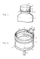
- FIG. 1 is a fragmentary perspective view of the tamper indicating package embodying the invention.
- FIG. 2 is a perspective view of the cap of the invention in inverted position illustrating a post forming operation thereon.
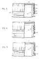
- FIG. 3 is an enlarged part sectional side elevational view of the cap and container finish combination of FIG. 1 with the cap in the partial section and threaded onto the container finish.
- FIG. 4 is a view similar to that of FIG. 3 after the cap has been partially removed.
- FIG. 5 is a view similar to that of FIG. 4 showing the position of the lower edge of the cap when it is fully reapplied on the container finish.
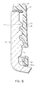
- FIG. 6 is a fragmentary enlarged sectional view of a portion of the cap and container shown in FIG. 3.
- FIG. 7 is a fragmentary enlarged sectional view of a portion of the package shown in FIG. 4.
- FIG. 8 is a fragmentary sectional view of a portion of the package shown in FIG. 5.
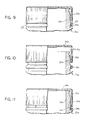
- FIG. 9 is a fragmentary part sectional side elevational view of a modified form of package.
- FIG. 10 is a view similar to FIG. 9 after the cap has been removed.
- FIG. 11 is a view similar to FIG. 10 showing the relative position of the cap when it is reapplied to the container.
- FIG. 12 is a fragmentary view on an enlarged scale of a portion of the package shown in FIG. 9.
- the tamper indicating package 20 embodying the invention comprises a glass container 21 having a finish or neck 22.
- a closure 23 is formed of a thermoplastic material, such as polypropylene, molded as a single unit and comprises a generally disc-shaped base 24 and a cylindrical depending skirt 25.
- the inner surface of skirt 25 is formed with threads 26 which are adapted to engage complementary threads 27 on finish 22.
- An integral tamper indicating band 28 extends downwardly from skirt 25.
- Band 28 is generally cylindrical and has essentially the same external diameter as that of the skirt 25 of the closure 23.
- the band 28 is joined to the lower end of the skirt 25 by a plurality of frangible bridges 29.
- circumferentially spaced stops are formed integral with the band 28 and are primarily for use when the closures are molded so as to permit the pushing of the molded closure from the mold die without compressing the frangible bridges 29, yet permit the removal of the closure with attached indicator band 28.
- the stops are not attached to the lower skirt of the closure in any way.
- An integrally formed annular stop ring 31 extends from the inner surface of band 28.
- the cap When the cap is initially formed, it will take the configuration shown in FIG. 2. With the stop ring 31 in the inverted form shown in FIG. 2, the stop ring will extend inwardly and upwardly relative to the indicator band 28 with an included angle of approximately 30°. As perhaps can be best seen in FIGS. 6 and 7, the stop ring 31 is integrally formed on the indicator band 28 and has a free end 32 of somewhat thicker configuration than the thickness of the connection between the ring 28 and band 25.
- the closure 23 After the closure 23 is molded in the shape illustrated in FIG. 2, the closure 23 is rotated about its central vertical axis, parallel to the cylindrical skirt and, at the same time, the stop ring 31 is engaged by a beveled rotating wheel 33.
- Wheel 33 is shown as being mounted on a shaft 34, it being understood that the shaft 34 is driven by any suitable drive means.
- the closure 23 is depicted as being positioned on a rotating pad 35 carried at the upper end of a shaft 36. With the closure being rotated on the pad 35 and the wheel 33 rotating in engagement with the stop ring 31, the stop ring 31 is forced to bend downwardly and inwardly in the inverted position of the cap, as shown in FIG. 2, with the stop ring 31 being pushed through an angle of approximately 120° from the "as-molded" angle.
- the tucking of the ring 31 into the position illustrated is made possible by the fact that it is joined to the inner surface of the band 28 by a thin section 36a which serves as a hinge. This is clearly illustrated in FIGS. 3-8 where the locking ring is hingedly formed integrally with a cylindrical portion of a tamper indicating band.
- the ring 31 may be moved into the "tucked” position shortly after the molding operation before the plastic sets or at any time thereafter prior to being used with the container-closure combination.
- the ring will assume the "tucked” position when physically moved into this position and will remain in the position unless returned physically to the "as-molded” position illustrated in FIG. 2.
- the "tucking" or untucking of the ring does not require any heating of the plastic and may be carried out with the plastic at room temperature.
- the ring When the ring is in its "as-molded” position, it will remain in that position until being physically hinged inwardly. Thus, the ring position is “bistable".
- the diameter formed by the inner edge or free edge of the ring is smaller than the diameter of the circle where the ring is joined to the wall portion of the band. This results in stability in either position on opposite sides (up or down) of a horizontal plane passing normal to the band 28 at the point of attachment of the ring 31 to the band 28.
- the ring 31 When the ring 31 is being moved from one stable position to the other, it will be placed under compressive stress until it passes over dead center, at which time it will relieve these stresses by assuming the stable position on the other side of the horizontal plane.
- One way of moving the locking ring, such as ring 31, from its as-molded position to the locking or tucked position is by pushing the inner edge of the ring down at one area in its circumference with the thumb and progressively pushing down the adjacent areas until the full circumference has been pushed down below the top edge of the band.
- Another method of moving the locking ring into locking position from its as-molded position would be by engaging the ring with a beveled wheel while rotating the band about its central axis as described above. This latter method is illustrated in United States patent 4,613,052, where a ring is attached to the lower skirt of a closure.
- the finish 22 of the container 21, as best seen in FIG. 6, has a first or upper radially outwardly curved bead 37 formed therein which extends outward to an extent somewhat greater than the external dimensions of the threads 27.
- the bead 37 has a lower surface 38 which may be termed a breaker ledge.
- the stop ring 31 will have its free end 32 positioned beneath a second bead 39 (see below) and either in engagement with or closely spaced beneath the breaker surface 38.
- the finish 22 of the container 21 is also formed with a second radial bead 39 which is below the bead 37 and has a smaller diameter than bead 37 and its breaker ledge 38.
- the bead 39 extends inwardly as well but has its outer largest diameter connected to the first bead 37 by an intermediate annular concave groove or recess 40.
- the finish is provided with an annular surface 41 that extends axially downwardly and radially inwardly from the second bead 39. As shown, the surface 41 is concave in cross section.
- the stop ring 28 will be prevented from moving downwardly by engagement of the free end 32 of ring 31 with the groove or recess 40 (FIGS. 4, 7).
- the container 21a is made of plastic such as polyethylene or polypropylene.
- the second surface 41a is made straight in axial cross section.
- the container 21a and closure 23a are similar to the form shown in FIGS. 1-8. Accordingly, similar parts are marked with similar reference numerals with the suffix "a".
Landscapes
- Engineering & Computer Science (AREA)
- Mechanical Engineering (AREA)
- Closures For Containers (AREA)
- Bag Frames (AREA)
- Packages (AREA)
- Cartons (AREA)
- Table Devices Or Equipment (AREA)
- Details Of Rigid Or Semi-Rigid Containers (AREA)
Abstract
Description
- The present invention is directed to a one-piece, molded plastic, or the like, closure that may be threaded onto the finish or neck of a container, and in which a tamper-indicating band is joined to the bottom of the closure skirt by a series of frangible bridges. An inwardly and upwardly turned flexible, stop band is molded inside the indicator band and in combination with a radial bead on the container finish will resist removal of the closure without rupture of the frangible bridges.
- Tamper-indicating closures are not new and one recently patented example can be found in United States Patent 4,394,918, issued to Jean Grussen on July 26, 1983. In this patent a threaded closure carries a hold ring that is joined to the bottom of the cap skirt by a series of breakable tabs and the hold ring has an inside diameter that is at least equal to the outside diameter of the cap skirt. A plurality of lock lugs supported on the ring are inclined upwardly and inwardly and are intended to hook behind a collar or mating ring on the container neck to prevent the hold ring from being lifted off the container neck when the cap is unscrewed. An unbreakable flange is provided between the cap skirt and the ring and serves as a hinge for the cap when it is unscrewed.
- Other tamper-indicating closures that thread on the containers are made fairly simple, but these tamper-indicating rings generally require cooperating, specifically designed, means on the container.
- Some other tamper-indicating systems have been used in which a frangible band is formed at the bottom of the closure skirt and requires the actual destruction of the band before the closure can be unscrewed. These also may require special ramps and ledges to be formed on the container shoulders or necks. The problem with these systems is that once the band is removed and discarded, it may not be readily apparent that the closure has been unscrewed.
- Much of the same can be said for the systems that use heat shrunk or stretch bands that engage the closure and the container. Furthermore, heat shrinking adds an additional step to the sealing process and requires special equipment beyond the normal threaded closure applying machines.
- In United States Patent 4,550,884 and United States Patent 4,613,052 having a common assignee with the present application, there is disclosed and claimed a screw type cap of plastic with a tamper-indicating ring or band that is carried at the lower end of the skirt of the closure with frangible bridges forming the connection. The removal of the closure results in the indicating band being severed from the closure and the band is moved to a lower position on the neck and is prevented from being returned to its, as applied, position. A container has a finish, below external threads which is formed with an inwardly and downwardly tapering side wall which leads to an abrupt, horizontal ledge such that when an indicating band is severed from a closure, on removal, the band falls below the ledge and cannot be returned. The closure is formed with internal threads in the skirt and at the bottom of the skirt a band or ring of about the same external diameter as the cap is formed with frangible bridges joining the band to the skirt. Within the indicating band an inwardly extending flexible stop ring is formed integral with the indicating band. A particular finish on the container provides a pair of radial ledges which extend outwardly below the threads on the container neck. These ledges are vertically displaced relative to each other and are joined by an inwardly tapering wall which is adapted to form the surface on which the stop ring will be seated when the closure is applied. The stop ring prevents removal of the closure without the separation of the indicating band from the closure skirt. A similar closure is described in EP-A-0 213 742 (published 11.03.87), wherein an upper bead on the container finish prevents removal of the closure until the skirt is separated from the indicating band, and a lower bead on the finish limits the radially inward movement of the stop ring.
- Among the objectives of the present invention are to provide a tamper indicating package wherein the tamper indicating band is positively caused to dropped away from the closure after being severed and an intermediate tapered or concave portion between the two beads so that a user can readily see and feel that the band has been severed.
- In accordance with the invention, the tamper indicating package comprises a one-piece molded closure of plastic which threads onto a container such that when the closure is unthreaded, a tamper-indicating ring becomes separated from the lower end of the closure skirt. The indicating ring or band is joined to the closure along a weakened frangible line and a flexible stop ring is formed within the band and extends inwardly and upwardly when the closure is applied to a container finish. The container finish has a first radial bead, a second radial bead spaced axially below the first bead, and an intermediate tapered or concave surface between the first radial bead and second radial bead. A further surface extends from the second bead axially downwardly and radially inwardly and the flexible end of the stop ring rests on this surface between the two beads, when the closure is applied. When the closure is unthreaded to remove it, the free end of the stop ring passes over the second bead into the recess formed by the surface between the two beads and the frangible portion is broken leaving the ring and band in this position. Upon subsequent reapplication of the closure, the closure skirt engages the band causing the band to pass over the second bead on the finish so that the band falls away but remains on the container to indicate that the band has been severed.
- FIG. 1 is a fragmentary perspective view of the tamper indicating package embodying the invention.
- FIG. 2 is a perspective view of the cap of the invention in inverted position illustrating a post forming operation thereon.
- FIG. 3 is an enlarged part sectional side elevational view of the cap and container finish combination of FIG. 1 with the cap in the partial section and threaded onto the container finish.
- FIG. 4 is a view similar to that of FIG. 3 after the cap has been partially removed.
- FIG. 5 is a view similar to that of FIG. 4 showing the position of the lower edge of the cap when it is fully reapplied on the container finish.
- FIG. 6 is a fragmentary enlarged sectional view of a portion of the cap and container shown in FIG. 3.
- FIG. 7 is a fragmentary enlarged sectional view of a portion of the package shown in FIG. 4.
- FIG. 8 is a fragmentary sectional view of a portion of the package shown in FIG. 5.
- FIG. 9 is a fragmentary part sectional side elevational view of a modified form of package.
- FIG. 10 is a view similar to FIG. 9 after the cap has been removed.
- FIG. 11 is a view similar to FIG. 10 showing the relative position of the cap when it is reapplied to the container.
- FIG. 12 is a fragmentary view on an enlarged scale of a portion of the package shown in FIG. 9.
- Referring to FIGS. 1-8, the
tamper indicating package 20 embodying the invention comprises aglass container 21 having a finish orneck 22. Aclosure 23 is formed of a thermoplastic material, such as polypropylene, molded as a single unit and comprises a generally disc-shaped base 24 and a cylindrical dependingskirt 25. The inner surface ofskirt 25 is formed withthreads 26 which are adapted to engagecomplementary threads 27 onfinish 22. An integraltamper indicating band 28 extends downwardly fromskirt 25.Band 28 is generally cylindrical and has essentially the same external diameter as that of theskirt 25 of theclosure 23. Theband 28 is joined to the lower end of theskirt 25 by a plurality offrangible bridges 29. In addition, circumferentially spaced stops (not shown) are formed integral with theband 28 and are primarily for use when the closures are molded so as to permit the pushing of the molded closure from the mold die without compressing thefrangible bridges 29, yet permit the removal of the closure with attachedindicator band 28. The stops are not attached to the lower skirt of the closure in any way. - An integrally formed
annular stop ring 31 extends from the inner surface ofband 28. When the cap is initially formed, it will take the configuration shown in FIG. 2. With thestop ring 31 in the inverted form shown in FIG. 2, the stop ring will extend inwardly and upwardly relative to theindicator band 28 with an included angle of approximately 30°. As perhaps can be best seen in FIGS. 6 and 7, thestop ring 31 is integrally formed on theindicator band 28 and has afree end 32 of somewhat thicker configuration than the thickness of the connection between thering 28 andband 25. After theclosure 23 is molded in the shape illustrated in FIG. 2, theclosure 23 is rotated about its central vertical axis, parallel to the cylindrical skirt and, at the same time, thestop ring 31 is engaged by a beveled rotatingwheel 33.Wheel 33 is shown as being mounted on ashaft 34, it being understood that theshaft 34 is driven by any suitable drive means. Furthermore, as shown in FIG. 2, theclosure 23 is depicted as being positioned on a rotatingpad 35 carried at the upper end of ashaft 36. With the closure being rotated on thepad 35 and thewheel 33 rotating in engagement with thestop ring 31, thestop ring 31 is forced to bend downwardly and inwardly in the inverted position of the cap, as shown in FIG. 2, with thestop ring 31 being pushed through an angle of approximately 120° from the "as-molded" angle. - The tucking of the
ring 31 into the position illustrated is made possible by the fact that it is joined to the inner surface of theband 28 by athin section 36a which serves as a hinge. This is clearly illustrated in FIGS. 3-8 where the locking ring is hingedly formed integrally with a cylindrical portion of a tamper indicating band. - It should be understood that the
ring 31 may be moved into the "tucked" position shortly after the molding operation before the plastic sets or at any time thereafter prior to being used with the container-closure combination. The ring will assume the "tucked" position when physically moved into this position and will remain in the position unless returned physically to the "as-molded" position illustrated in FIG. 2. The "tucking" or untucking of the ring does not require any heating of the plastic and may be carried out with the plastic at room temperature. When the ring is in its "as-molded" position, it will remain in that position until being physically hinged inwardly. Thus, the ring position is "bistable". This is because the diameter formed by the inner edge or free edge of the ring is smaller than the diameter of the circle where the ring is joined to the wall portion of the band. This results in stability in either position on opposite sides (up or down) of a horizontal plane passing normal to theband 28 at the point of attachment of thering 31 to theband 28. When thering 31 is being moved from one stable position to the other, it will be placed under compressive stress until it passes over dead center, at which time it will relieve these stresses by assuming the stable position on the other side of the horizontal plane. One way of moving the locking ring, such asring 31, from its as-molded position to the locking or tucked position is by pushing the inner edge of the ring down at one area in its circumference with the thumb and progressively pushing down the adjacent areas until the full circumference has been pushed down below the top edge of the band. Another method of moving the locking ring into locking position from its as-molded position would be by engaging the ring with a beveled wheel while rotating the band about its central axis as described above. This latter method is illustrated in United States patent 4,613,052, where a ring is attached to the lower skirt of a closure. - The
finish 22 of thecontainer 21, as best seen in FIG. 6, has a first or upper radially outwardlycurved bead 37 formed therein which extends outward to an extent somewhat greater than the external dimensions of thethreads 27. Thebead 37 has alower surface 38 which may be termed a breaker ledge. As shown in FIG. 6, when theclosure 23 is threaded down over thecontainer finish 22, thestop ring 31 will have itsfree end 32 positioned beneath a second bead 39 (see below) and either in engagement with or closely spaced beneath thebreaker surface 38. Thefinish 22 of thecontainer 21 is also formed with a secondradial bead 39 which is below thebead 37 and has a smaller diameter thanbead 37 and itsbreaker ledge 38. Thebead 39 extends inwardly as well but has its outer largest diameter connected to thefirst bead 37 by an intermediate annular concave groove or recess 40. - The finish is provided with an
annular surface 41 that extends axially downwardly and radially inwardly from thesecond bead 39. As shown, thesurface 41 is concave in cross section. - As can readily be seen when viewing FIG. 6, when the closure is applied, the
free end 32 of thering 31 flexes outwardly successively over thefirst bead 37 andsecond bead 39 and engages thesurface 41. When theclosure 23 is unthreaded, skirt 25carries band 28 andring 31 axially outwardly causing thefree end 32 ofring 31 to flex outwardly oversecond bead 39 and then flex inwardly bringing thefree end 32 of thestop ring 31 beneath thebreaker surface 38 of thebead 37. The moving or unthreading of theclosure 23, as illustrated in FIGS. 4 and 7, results in the breaking of thebridges 29 since thestop ring 31 cannot move above thebead 37. Thus, after thebridges 29 are broken, theindicator band 28 and thestop ring 31 have itsfree end 32 remaining between thebead 37 andbead 39 of thecontainer 21. - When the threaded closure is removed from the container finish, the
stop ring 31 will be prevented from passing back over thebead 37 by the engagement of theend 32 of thestop ring 31 with theledge 38 of the bead 37 (FIGS. 4, 7). - After the closure has been unthreaded, the
stop ring 28 will be prevented from moving downwardly by engagement of thefree end 32 ofring 31 with the groove or recess 40 (FIGS. 4, 7). - When the closure is reapplied, the free edge of the
skirt 25 engages theband 28 and moves it downwardly causing thering 31 to flex overbead 39 so that the band falls away but remains on the container to indicate that the band has been severed. - In the form of the invention set forth in FIGS. 9-12, the
container 21a is made of plastic such as polyethylene or polypropylene. To accommodate manufacturing procedures such as blow molding, thesecond surface 41a is made straight in axial cross section. In all other respects, thecontainer 21a andclosure 23a are similar to the form shown in FIGS. 1-8. Accordingly, similar parts are marked with similar reference numerals with the suffix "a".
Claims (6)
- A tamper indicating package (20) comprising
a container (21) having a finish (22) having a free end,
a closure (23) comprising a base wall (24) and a peripheral skirt (25),
a tamper indicating band (28) connected to the skirt along a weakened frangible line,
a stop ring (31) flexibly connected to said band (28) and extending radially inwardly and axially toward the base wall of the closure,
said finish and said closure having interengaging means (26, 27) which are engageable and disengageable by relative rotation between the closure and containers,
said finish having a first annular bead (37),
a second annular bead (39) spaced axially from said first annular bead,
a first surface (40) defining a recess between said beads, and
a second surface (41) extending from said second bead radially inwardly and axially away from the free end of the finish,
said stop ring (31) normally engaging the second surface (41) when said closure is engaged with said container such that when the closure is rotated to remove the closure from the container, said stop ring (31) is moved axially and flexes over the second bead (39) bringing the free end (32) of the stop ring into engagement with said first bead (37) and continued relative rotation of the closure causes the band to be severed along the weakened line leaving the band (28) with the free end of the stop ring in said recess, and when the closure is reapplied to the container, the free edge of said skirt (25) engages said tamper indicating band (28) to move the ring (31) out of engagement with the recess and force the band (28) to fall away from the skirt. - The package set forth in claim 1 wherein said second surface (41) is concave in axial cross section.
- The package set forth in claim 2 wherein said container is made of glass.
- The package set forth in claim 1 wherein said second surface (41a) is straight in axial cross section.
- The package set forth in claim 4 wherein said container is made of plastic.
- The package set forth in claim 1 wherein said second bead (39) has a lesser diameter than said first bead (37).
Priority Applications (1)
| Application Number | Priority Date | Filing Date | Title |
|---|---|---|---|
| AT87310648T ATE75686T1 (en) | 1987-02-17 | 1987-12-03 | WARRANTY CLOSURE FOR CONTAINERS. |
Applications Claiming Priority (2)
| Application Number | Priority Date | Filing Date | Title |
|---|---|---|---|
| US07/015,764 US4721218A (en) | 1987-02-17 | 1987-02-17 | Tamper indicating package |
| US15764 | 1987-02-17 |
Publications (3)
| Publication Number | Publication Date |
|---|---|
| EP0279119A2 EP0279119A2 (en) | 1988-08-24 |
| EP0279119A3 EP0279119A3 (en) | 1989-07-19 |
| EP0279119B1 true EP0279119B1 (en) | 1992-05-06 |
Family
ID=21773467
Family Applications (1)
| Application Number | Title | Priority Date | Filing Date |
|---|---|---|---|
| EP87310648A Expired - Lifetime EP0279119B1 (en) | 1987-02-17 | 1987-12-03 | Tamper indicating package |
Country Status (12)
| Country | Link |
|---|---|
| US (1) | US4721218A (en) |
| EP (1) | EP0279119B1 (en) |
| JP (1) | JPS63203563A (en) |
| AT (1) | ATE75686T1 (en) |
| AU (1) | AU586942B2 (en) |
| BR (1) | BR8800587A (en) |
| CA (1) | CA1288390C (en) |
| DE (1) | DE3778874D1 (en) |
| ES (1) | ES2030741T3 (en) |
| MX (1) | MX160135A (en) |
| NZ (1) | NZ222780A (en) |
| ZA (1) | ZA879376B (en) |
Families Citing this family (21)
| Publication number | Priority date | Publication date | Assignee | Title |
|---|---|---|---|---|
| JPH01165027U (en) * | 1988-05-11 | 1989-11-17 | ||
| US5219507A (en) * | 1989-07-27 | 1993-06-15 | Owens-Illinois Closure Inc. | Method of making a tamper indicating package |
| US5090788A (en) * | 1989-07-27 | 1992-02-25 | Owens-Illinois Closure Inc. | Tamper indicating package |
| US4971212A (en) * | 1989-10-06 | 1990-11-20 | Owens-Illinois Closure Inc. | Tamper indicating packages |
| CA2072365A1 (en) | 1989-12-28 | 1991-06-29 | Daniel L. La Rue | Tamper evident caps and methods for producing such caps |
| JPH07500795A (en) * | 1991-05-01 | 1995-01-26 | アンカー ホッキング パッケージング カンパニー | Push-to-install, scoop-to-remove lid |
| JP2555365Y2 (en) * | 1991-10-03 | 1997-11-19 | 日本クラウンコルク株式会社 | Cap with clear opening function |
| US5350078A (en) * | 1992-09-24 | 1994-09-27 | Tropicana Products, Inc. | Beverage bottle |
| US5282540A (en) * | 1992-11-23 | 1994-02-01 | Creative Packaging Corp. | Tamper band with flexible engagement member |
| US5295600A (en) * | 1993-02-25 | 1994-03-22 | Owens-Illinois Closure Inc. | Tamper indicating closure |
| US5443171A (en) * | 1993-03-26 | 1995-08-22 | Owens-Illinois Closure Inc. | Tamper indicating package |
| US5488888A (en) * | 1993-04-19 | 1996-02-06 | Owens-Illinois Closure Inc. | Method of forming bridges in tamper indicating closures |
| US6817276B1 (en) | 1993-04-19 | 2004-11-16 | Owens-Illinois Closure Inc. | Apparatus for forming bridges in tamper-indicating closures |
| US5522293A (en) * | 1993-10-14 | 1996-06-04 | Owens-Illinois Closure Inc. | Method and apparatus for accurately positioning a knife blade for scoring plastic tamper indicating closures |
| US5609262A (en) * | 1995-09-22 | 1997-03-11 | Rieke Corporation | Tamper evident, child-resistant closure |
| US6382443B1 (en) * | 1999-04-28 | 2002-05-07 | Owens-Illinois Closure Inc. | Tamper-indicating closure with lugs on a stop flange for spacing the flange from the finish of a container |
| JP4588149B2 (en) * | 2000-02-01 | 2010-11-24 | 大成化工株式会社 | Cap-type combined sealing device and container combination |
| US6355201B1 (en) | 2000-09-07 | 2002-03-12 | Captive Plastics, Inc. | Tamper-indicating closure with resilient locking projections |
| US7314366B2 (en) * | 2005-06-17 | 2008-01-01 | Owens-Illinois Closure Inc. | Apparatus and method for inverting a stop flange on a tamper-indicating closure |
| JP2006264743A (en) * | 2005-03-24 | 2006-10-05 | Maretaka Co Ltd | Closure device |
| JP2023545240A (en) * | 2020-10-15 | 2023-10-27 | テトラ ラバル ホールディングス アンド ファイナンス エス エイ | Lid spout assembly for packages and packages with lid spout assemblies |
Family Cites Families (5)
| Publication number | Priority date | Publication date | Assignee | Title |
|---|---|---|---|---|
| US4461390A (en) * | 1980-04-21 | 1984-07-24 | General Kap (P.R.) Corporation | Tamper-evident plastic closure |
| US4613052A (en) * | 1985-04-29 | 1986-09-23 | Owens-Illinois, Inc. | Tamper-indicating closure, container and combination thereof |
| US4669623A (en) * | 1985-06-28 | 1987-06-02 | General Kap Corporation | Container with double bead track system and frangible closure |
| AU591512B2 (en) * | 1985-07-31 | 1989-12-07 | Visy Industrial Plastics Pty Ltd | Tamper indicating closure member for containers |
| EP0213742B1 (en) * | 1985-07-31 | 1991-01-23 | Aci Australia Limited | Tamper indicating closure member for containers |
-
1987
- 1987-02-17 US US07/015,764 patent/US4721218A/en not_active Expired - Lifetime
- 1987-12-02 NZ NZ222780A patent/NZ222780A/en unknown
- 1987-12-03 AT AT87310648T patent/ATE75686T1/en active
- 1987-12-03 ES ES198787310648T patent/ES2030741T3/en not_active Expired - Lifetime
- 1987-12-03 DE DE8787310648T patent/DE3778874D1/en not_active Expired - Fee Related
- 1987-12-03 EP EP87310648A patent/EP0279119B1/en not_active Expired - Lifetime
- 1987-12-04 CA CA000553550A patent/CA1288390C/en not_active Expired - Fee Related
- 1987-12-14 ZA ZA879376A patent/ZA879376B/en unknown
-
1988
- 1988-01-07 MX MX10018A patent/MX160135A/en unknown
- 1988-01-19 AU AU10393/88A patent/AU586942B2/en not_active Ceased
- 1988-02-11 BR BR8800587A patent/BR8800587A/en not_active IP Right Cessation
- 1988-02-16 JP JP63032002A patent/JPS63203563A/en active Granted
Also Published As
| Publication number | Publication date |
|---|---|
| AU586942B2 (en) | 1989-07-27 |
| JPH0530699B2 (en) | 1993-05-10 |
| ATE75686T1 (en) | 1992-05-15 |
| BR8800587A (en) | 1988-09-27 |
| ES2030741T3 (en) | 1992-11-16 |
| ZA879376B (en) | 1988-08-31 |
| MX160135A (en) | 1989-12-06 |
| US4721218A (en) | 1988-01-26 |
| AU1039388A (en) | 1988-08-18 |
| EP0279119A3 (en) | 1989-07-19 |
| EP0279119A2 (en) | 1988-08-24 |
| CA1288390C (en) | 1991-09-03 |
| JPS63203563A (en) | 1988-08-23 |
| NZ222780A (en) | 1989-12-21 |
| DE3778874D1 (en) | 1992-06-11 |
Similar Documents
| Publication | Publication Date | Title |
|---|---|---|
| EP0279119B1 (en) | Tamper indicating package | |
| USRE33265E (en) | Tamper-indicating closure, container and combination thereof | |
| US4653657A (en) | Tamper indicating package | |
| US5462184A (en) | Tamper indicating package | |
| CA2001023C (en) | Tamper indicating package | |
| US5487481A (en) | Tamper evident plastic closure | |
| US4801031A (en) | Tamper-indicating closures and packages | |
| US4846361A (en) | Tamper-indicating closure for a container and improved capping without top loading | |
| EP0616951B1 (en) | Tamper indicating package | |
| GB2121392A (en) | Tamper-evident closure | |
| US4971212A (en) | Tamper indicating packages | |
| US5755347A (en) | Tamper indicating package | |
| US4923073A (en) | Tamper-indicating plastic closure | |
| US4667838A (en) | Tamper-evident closure with ribbed skirt | |
| US4645087A (en) | Tamper indicating device | |
| US4749095A (en) | Tamper-indicating closure and package | |
| EP0861792B1 (en) | Tamper-evident closure | |
| NZ228676A (en) | Screw cap and container; stop ring of cap indicating band engages beneath upper bead on container neck | |
| CA2139959C (en) | Tamper evident plastic closure |
Legal Events
| Date | Code | Title | Description |
|---|---|---|---|
| PUAI | Public reference made under article 153(3) epc to a published international application that has entered the european phase |
Free format text: ORIGINAL CODE: 0009012 |
|
| AK | Designated contracting states |
Kind code of ref document: A2 Designated state(s): AT BE CH DE ES FR GB IT LI NL SE |
|
| PUAL | Search report despatched |
Free format text: ORIGINAL CODE: 0009013 |
|
| AK | Designated contracting states |
Kind code of ref document: A3 Designated state(s): AT BE CH DE ES FR GB IT LI NL SE |
|
| 17P | Request for examination filed |
Effective date: 19890906 |
|
| 17Q | First examination report despatched |
Effective date: 19910227 |
|
| GRAA | (expected) grant |
Free format text: ORIGINAL CODE: 0009210 |
|
| ITF | It: translation for a ep patent filed | ||
| AK | Designated contracting states |
Kind code of ref document: B1 Designated state(s): AT BE CH DE ES FR GB IT LI NL SE |
|
| REF | Corresponds to: |
Ref document number: 75686 Country of ref document: AT Date of ref document: 19920515 Kind code of ref document: T |
|
| ET | Fr: translation filed | ||
| REF | Corresponds to: |
Ref document number: 3778874 Country of ref document: DE Date of ref document: 19920611 |
|
| REG | Reference to a national code |
Ref country code: ES Ref legal event code: FG2A Ref document number: 2030741 Country of ref document: ES Kind code of ref document: T3 |
|
| PLBE | No opposition filed within time limit |
Free format text: ORIGINAL CODE: 0009261 |
|
| STAA | Information on the status of an ep patent application or granted ep patent |
Free format text: STATUS: NO OPPOSITION FILED WITHIN TIME LIMIT |
|
| 26N | No opposition filed | ||
| REG | Reference to a national code |
Ref country code: FR Ref legal event code: CL |
|
| EAL | Se: european patent in force in sweden |
Ref document number: 87310648.8 |
|
| PGFP | Annual fee paid to national office [announced via postgrant information from national office to epo] |
Ref country code: NL Payment date: 20000929 Year of fee payment: 14 |
|
| PGFP | Annual fee paid to national office [announced via postgrant information from national office to epo] |
Ref country code: AT Payment date: 20001103 Year of fee payment: 14 |
|
| PGFP | Annual fee paid to national office [announced via postgrant information from national office to epo] |
Ref country code: SE Payment date: 20001201 Year of fee payment: 14 |
|
| PGFP | Annual fee paid to national office [announced via postgrant information from national office to epo] |
Ref country code: CH Payment date: 20001229 Year of fee payment: 14 |
|
| PGFP | Annual fee paid to national office [announced via postgrant information from national office to epo] |
Ref country code: BE Payment date: 20010118 Year of fee payment: 14 |
|
| PG25 | Lapsed in a contracting state [announced via postgrant information from national office to epo] |
Ref country code: AT Free format text: LAPSE BECAUSE OF NON-PAYMENT OF DUE FEES Effective date: 20011203 |
|
| PG25 | Lapsed in a contracting state [announced via postgrant information from national office to epo] |
Ref country code: SE Free format text: LAPSE BECAUSE OF NON-PAYMENT OF DUE FEES Effective date: 20011204 |
|
| PG25 | Lapsed in a contracting state [announced via postgrant information from national office to epo] |
Ref country code: LI Free format text: LAPSE BECAUSE OF NON-PAYMENT OF DUE FEES Effective date: 20011231 Ref country code: CH Free format text: LAPSE BECAUSE OF NON-PAYMENT OF DUE FEES Effective date: 20011231 Ref country code: BE Free format text: LAPSE BECAUSE OF NON-PAYMENT OF DUE FEES Effective date: 20011231 |
|
| REG | Reference to a national code |
Ref country code: GB Ref legal event code: IF02 |
|
| BERE | Be: lapsed |
Owner name: OWENS-ILLINOIS CLOSURE INC. Effective date: 20011231 |
|
| PG25 | Lapsed in a contracting state [announced via postgrant information from national office to epo] |
Ref country code: NL Free format text: LAPSE BECAUSE OF NON-PAYMENT OF DUE FEES Effective date: 20020701 |
|
| EUG | Se: european patent has lapsed |
Ref document number: 87310648.8 |
|
| REG | Reference to a national code |
Ref country code: CH Ref legal event code: PL |
|
| NLV4 | Nl: lapsed or anulled due to non-payment of the annual fee |
Effective date: 20020701 |
|
| PGFP | Annual fee paid to national office [announced via postgrant information from national office to epo] |
Ref country code: GB Payment date: 20041104 Year of fee payment: 18 |
|
| PGFP | Annual fee paid to national office [announced via postgrant information from national office to epo] |
Ref country code: FR Payment date: 20041201 Year of fee payment: 18 |
|
| PGFP | Annual fee paid to national office [announced via postgrant information from national office to epo] |
Ref country code: ES Payment date: 20041222 Year of fee payment: 18 |
|
| PGFP | Annual fee paid to national office [announced via postgrant information from national office to epo] |
Ref country code: DE Payment date: 20041230 Year of fee payment: 18 |
|
| PG25 | Lapsed in a contracting state [announced via postgrant information from national office to epo] |
Ref country code: IT Free format text: LAPSE BECAUSE OF NON-PAYMENT OF DUE FEES;WARNING: LAPSES OF ITALIAN PATENTS WITH EFFECTIVE DATE BEFORE 2007 MAY HAVE OCCURRED AT ANY TIME BEFORE 2007. THE CORRECT EFFECTIVE DATE MAY BE DIFFERENT FROM THE ONE RECORDED. Effective date: 20051203 Ref country code: GB Free format text: LAPSE BECAUSE OF NON-PAYMENT OF DUE FEES Effective date: 20051203 |
|
| PG25 | Lapsed in a contracting state [announced via postgrant information from national office to epo] |
Ref country code: ES Free format text: LAPSE BECAUSE OF NON-PAYMENT OF DUE FEES Effective date: 20051205 |
|
| PG25 | Lapsed in a contracting state [announced via postgrant information from national office to epo] |
Ref country code: DE Free format text: LAPSE BECAUSE OF NON-PAYMENT OF DUE FEES Effective date: 20060701 |
|
| GBPC | Gb: european patent ceased through non-payment of renewal fee |
Effective date: 20051203 |
|
| PG25 | Lapsed in a contracting state [announced via postgrant information from national office to epo] |
Ref country code: FR Free format text: LAPSE BECAUSE OF NON-PAYMENT OF DUE FEES Effective date: 20060831 |
|
| REG | Reference to a national code |
Ref country code: FR Ref legal event code: ST Effective date: 20060831 |
|
| REG | Reference to a national code |
Ref country code: ES Ref legal event code: FD2A Effective date: 20051205 |