EP0278934B1 - Nebeneinander angebrachte Befestigungsmittel - Google Patents
Nebeneinander angebrachte Befestigungsmittel Download PDFInfo
- Publication number
- EP0278934B1 EP0278934B1 EP88850036A EP88850036A EP0278934B1 EP 0278934 B1 EP0278934 B1 EP 0278934B1 EP 88850036 A EP88850036 A EP 88850036A EP 88850036 A EP88850036 A EP 88850036A EP 0278934 B1 EP0278934 B1 EP 0278934B1
- Authority
- EP
- European Patent Office
- Prior art keywords
- fastener
- collated
- head
- adjacent
- shank
- Prior art date
- Legal status (The legal status is an assumption and is not a legal conclusion. Google has not performed a legal analysis and makes no representation as to the accuracy of the status listed.)
- Expired - Lifetime
Links
- 230000004048 modification Effects 0.000 description 2
- 238000012986 modification Methods 0.000 description 2
- 239000002023 wood Substances 0.000 description 2
- 229910000831 Steel Inorganic materials 0.000 description 1
- 230000001154 acute effect Effects 0.000 description 1
- 229910052782 aluminium Inorganic materials 0.000 description 1
- XAGFODPZIPBFFR-UHFFFAOYSA-N aluminium Chemical compound [Al] XAGFODPZIPBFFR-UHFFFAOYSA-N 0.000 description 1
- 230000002860 competitive effect Effects 0.000 description 1
- 229910052751 metal Inorganic materials 0.000 description 1
- 239000002184 metal Substances 0.000 description 1
- 150000002739 metals Chemical class 0.000 description 1
- 238000000034 method Methods 0.000 description 1
- 230000008520 organization Effects 0.000 description 1
- 239000010959 steel Substances 0.000 description 1
Images

Classifications
-
- F—MECHANICAL ENGINEERING; LIGHTING; HEATING; WEAPONS; BLASTING
- F16—ENGINEERING ELEMENTS AND UNITS; GENERAL MEASURES FOR PRODUCING AND MAINTAINING EFFECTIVE FUNCTIONING OF MACHINES OR INSTALLATIONS; THERMAL INSULATION IN GENERAL
- F16B—DEVICES FOR FASTENING OR SECURING CONSTRUCTIONAL ELEMENTS OR MACHINE PARTS TOGETHER, e.g. NAILS, BOLTS, CIRCLIPS, CLAMPS, CLIPS OR WEDGES; JOINTS OR JOINTING
- F16B15/00—Nails; Staples
- F16B15/08—Nails; Staples formed in integral series but easily separable
Definitions
- This invention relates to fasteners. More particularly, it refers to fasteners usable in a collated strip for hammer tools.
- the fasteners used with this invention relate to prior fasteners shown in co-pending U.S. Application Serial No. 721,757, filed on April 10, 1985.
- collated fasteners there are many types of collated fasteners in use including the common and finishing smooth shank nails and the ring shank nail for increased holding power beyond that of a common round nail. Such fasteners require some tape or wire to interconnect the nails into a collated strip. None of such fasteners is self-interconnecting or locking to form a collated strip of self-contained fasteners. Many of the fasteners of the prior art are furthermore wasteful, being fabricated from an excess of steel, aluminum or other metals, such excess being of increasing importance as a competitive consideration.
- DE-A-2 319 374 discloses a plurality of fasteners collated together in a strip in a side by side relationship for use in a fastener tool, each fastener comprising :
- My collated fasteners are a plurality of fasteners having an elongated shank and an enlarged flattened head integral with one end of the shank.
- the shank in the preferred fastener has a central core with ten spaced side walls radially extending from the core, the walls conforming substantially in length with the length of the shank and forming at least a five-pointed star in cross section.
- the head has a slot with an entrance at the rim of the head which rides on a converging pair of side walls forming a star point in an adjacent fastener.
- One converging pair of sidewalls has a notch adjacent the head for slidable engagement with the slot in the head of the adjacent fastener. A blow to the head of one fastener causes disengagement from the notch and movement of the fastener along the length of the converging sidewalls of the adjacent fastener.
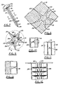
- the collated fastener unit 10 shown in Fig. 1 contains a plurality of identical fasteners 12 shown in Fig. 7.
- Each fastener 12 has an elongated shank 14, an elongated central core 16, five elongated radially protruding fins 18 from core 16 and an outer edge 20 on each fin 18.
- the fastener may have as few as three fins and as many as eleven.
- the cross-section of the shank 14 appears as star-shaped since each of the fins 18 taper from the core 16 outwardly to a rounded edge 20 at a point farthest from the core 16.
- a flat head 22 and point 24 of fastener 12 terminate each end of the shank 14.
- Shank 14 terminates at its first end 19 at the bottom 23 of head 22.
- the second end 21 of the shank terminates in point 24.
- the space between adjacent fins 18 forms a cup 26 which in an alternate embodiment shown in Fig. 9 contains serrations 28 for greater holding resistance when the fastener 12 is inserted into wood 15.
- Head 22 contains on its rim 25 a cutout flat end dovetail slot 30, fishtail slot 32, or other form 34 or 37 depending on the desired design.
- Each slot is designed to capture two adjacent fins 18 on the shank 14 of the next adjacent fastener. In a common nail as seen in Fig. 15 the shank is held by the slot of the adjacent fastener because such slot surrounds the cross sectional counterline of the shank.
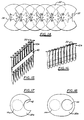
- the collated fastener unit 10 is formed by the slot 30 in fastener 12a capturing two adjacent fins 18 from fastener 12b, the slot in fastener 12b capturing two adjacent fins 18 from fastener 12c and so on until the slot on fastener 12k captures the two fins on fastener 121.
- a notch 36 on each shank 14 juxtaposed to head 22 prevents the adjacent fasteners from sliding apart. However, the notch 36 is overcome by the force of an automatic hammer gun striking head 22 so that the fasteners 12 can be released in order from 12a to 121 in response to the action of the automatic hammer gun.
- a second notch 38 is cut out of head 22 for use in providing closer spacing between shanks of a large headed fastener. This facilitates driving of the fastener over the centerline of the shank.
- the collated strip 10 can contain a band 40 for ease of transportation or can be lightly glued together. However, this is not necessary for the use of the collated strip 10.
- the collated strip 10 containing fasteners 12a to 121 will have each end point 24 slightly above the adjacent forward facing fastener so that the bottom strip 10 will form an acute angle with a flat surface below the strip 10.
- the fastener at the lower level will be struck first on its head to disengage from the collated strip.
- shank 14 is usually centered below the head 22 of each fastener as seen in Figs. 2, 3, 6 and 14, it is not necessary to maintain such a configuration. As seen in Fig. 17, the shank 14a is offset from the center of head 22a. In like manner, shank 14a in Fig. 18 is offset from the center of head 22a. Moreover, the opening 44 can be substituted for slot 42 as an alternate fastener head configuration.
- roofing nails as seen in Fig. 16 also can be formed into a collated strip 10b according to this invention by forming each nail in the manner of the fastener shown in Figs. 4 and 5.
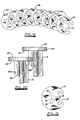
- Fasteners such as roofing nails seen in Fig. 19 can form a coil 46 which can be employed in nail guns designed to handle such a configuration.
- a quick fall away plane 48 can be utilized in shank 14 as seen in Fig. 20 so that when the adjacent fastener is disengaged from notch 36a by the fastener hammer gun action, it easily falls away from its adjacent fastener.
- No quick fall away plane 48 is present in the alternative embodiment of fig. 21, all three fins 18 being the same size.
- the roofing nail of fig 21 may be coiled and used in substantially the same manner as the roofing nails of fig 19.
Landscapes
- Engineering & Computer Science (AREA)
- General Engineering & Computer Science (AREA)
- Mechanical Engineering (AREA)
- Slide Fasteners, Snap Fasteners, And Hook Fasteners (AREA)
- Joining Of Building Structures In Genera (AREA)
- Superconductors And Manufacturing Methods Therefor (AREA)
- Absorbent Articles And Supports Therefor (AREA)
- Portable Nailing Machines And Staplers (AREA)
- Addition Polymer Or Copolymer, Post-Treatments, Or Chemical Modifications (AREA)
- Cold Cathode And The Manufacture (AREA)
- Sanitary Device For Flush Toilet (AREA)
- Coupling Device And Connection With Printed Circuit (AREA)
Claims (15)
Priority Applications (1)
| Application Number | Priority Date | Filing Date | Title |
|---|---|---|---|
| AT88850036T ATE72023T1 (de) | 1987-02-06 | 1988-02-01 | Nebeneinander angebrachte befestigungsmittel. |
Applications Claiming Priority (2)
| Application Number | Priority Date | Filing Date | Title |
|---|---|---|---|
| US1209987A | 1987-02-06 | 1987-02-06 | |
| US12099 | 1987-02-06 |
Publications (3)
| Publication Number | Publication Date |
|---|---|
| EP0278934A2 EP0278934A2 (de) | 1988-08-17 |
| EP0278934A3 EP0278934A3 (en) | 1989-12-27 |
| EP0278934B1 true EP0278934B1 (de) | 1992-01-22 |
Family
ID=21753388
Family Applications (1)
| Application Number | Title | Priority Date | Filing Date |
|---|---|---|---|
| EP88850036A Expired - Lifetime EP0278934B1 (de) | 1987-02-06 | 1988-02-01 | Nebeneinander angebrachte Befestigungsmittel |
Country Status (9)
| Country | Link |
|---|---|
| EP (1) | EP0278934B1 (de) |
| JP (2) | JPS63270907A (de) |
| AT (1) | ATE72023T1 (de) |
| AU (1) | AU583759B2 (de) |
| BR (1) | BR8800448A (de) |
| CA (1) | CA1290599C (de) |
| DE (1) | DE3867860D1 (de) |
| ES (1) | ES2028366T3 (de) |
| GR (1) | GR3004115T3 (de) |
Families Citing this family (4)
| Publication number | Priority date | Publication date | Assignee | Title |
|---|---|---|---|---|
| US4973211A (en) * | 1985-04-10 | 1990-11-27 | Star Fasteners International, Inc. | Star fasteners |
| DE4240605A1 (de) * | 1992-12-03 | 1994-06-09 | Hardo Befestigungen Gmbh | Befestigungselement |
| FR2857336B3 (fr) * | 2003-07-08 | 2005-12-02 | Georges Gregnic | Conditionnement de crochets de couverture en lot individuel standard pour composer chacun de rangs de (l'ourne ou echellee) |
| PL3792507T3 (pl) * | 2019-09-16 | 2024-11-25 | Bea Gmbh | Pas gwoździe z transponderami rfid oraz sposób wytwarzania |
Family Cites Families (9)
| Publication number | Priority date | Publication date | Assignee | Title |
|---|---|---|---|---|
| NL99488C (de) * | 1959-06-10 | |||
| US3696701A (en) * | 1969-12-29 | 1972-10-10 | Textron Inc | Nail having a pair of outwardly diverging head elements shaped to provide packaging, driving and fastening effectiveness and package thereof |
| JPS5013073B1 (de) * | 1970-07-08 | 1975-05-16 | ||
| US3835991A (en) * | 1972-09-15 | 1974-09-17 | Senco Products | Nail and method and apparatus for making same |
| JPS5013073U (de) * | 1973-06-02 | 1975-02-10 | ||
| DE2440847A1 (de) * | 1974-08-26 | 1976-03-18 | Hilti Ag | Nagel |
| JPS5262764U (de) * | 1975-11-05 | 1977-05-09 | ||
| DE2756494A1 (de) * | 1977-12-19 | 1979-06-21 | Publiplast Werbemittel Gmbh & | Nagel |
| US4755091A (en) * | 1985-04-10 | 1988-07-05 | Star Fasteners International, Inc. | Star fastener |
-
1988
- 1988-02-01 EP EP88850036A patent/EP0278934B1/de not_active Expired - Lifetime
- 1988-02-01 CA CA000557846A patent/CA1290599C/en not_active Expired - Lifetime
- 1988-02-01 ES ES198888850036T patent/ES2028366T3/es not_active Expired - Lifetime
- 1988-02-01 AT AT88850036T patent/ATE72023T1/de not_active IP Right Cessation
- 1988-02-01 DE DE8888850036T patent/DE3867860D1/de not_active Expired - Fee Related
- 1988-02-04 BR BR8800448A patent/BR8800448A/pt not_active IP Right Cessation
- 1988-02-05 JP JP63025539A patent/JPS63270907A/ja active Pending
- 1988-02-05 AU AU11337/88A patent/AU583759B2/en not_active Ceased
-
1992
- 1992-03-19 GR GR920400490T patent/GR3004115T3/el unknown
- 1992-07-03 JP JP1992046575U patent/JP2526990Y2/ja not_active Expired - Lifetime
Also Published As
| Publication number | Publication date |
|---|---|
| JP2526990Y2 (ja) | 1997-02-26 |
| ATE72023T1 (de) | 1992-02-15 |
| JPS63270907A (ja) | 1988-11-08 |
| AU1133788A (en) | 1988-08-11 |
| JPH0680907U (ja) | 1994-11-15 |
| ES2028366T3 (es) | 1992-07-01 |
| BR8800448A (pt) | 1988-09-20 |
| AU583759B2 (en) | 1989-05-04 |
| GR3004115T3 (de) | 1993-03-31 |
| CA1290599C (en) | 1991-10-15 |
| EP0278934A2 (de) | 1988-08-17 |
| EP0278934A3 (en) | 1989-12-27 |
| DE3867860D1 (de) | 1992-03-05 |
Similar Documents
| Publication | Publication Date | Title |
|---|---|---|
| US4815910A (en) | Collated nail strip | |
| US20020131843A1 (en) | Fasteners with improved retaining effect | |
| EP0537807B1 (de) | Befestigungsmittel mit kleeblattförmiger Ausnehmung und Werkzeug-Einführ-Schrägen | |
| US4482132A (en) | Nail removing hammer | |
| US5988020A (en) | Hammerhead | |
| US6729208B1 (en) | Tool for removing fasteners | |
| US5159858A (en) | Framing hammer construction | |
| US5971688A (en) | Fastener for laminate flooring | |
| EP0278934B1 (de) | Nebeneinander angebrachte Befestigungsmittel | |
| JPS647242B2 (de) | ||
| EP2418049A2 (de) | Schnellanschlussnuss | |
| US3935945A (en) | Open sided partially circular headed nail with recess along the open-sided edge thereof and stick package formed therefrom | |
| US6598858B2 (en) | Multipurpose combination hand tool | |
| US4240478A (en) | Compact hammer with recessed face and notched claw | |
| US4561635A (en) | Nail removing hammer | |
| US5865585A (en) | Angled chisel point brad and method therefor | |
| US5165588A (en) | Nail driver and nail | |
| US4182218A (en) | Expansion core anchor | |
| US20060048370A1 (en) | Method and apparatus for joining a handle to hammer head | |
| TW200932450A (en) | An improved fastener and driving tool | |
| US4121715A (en) | Stackable fastener assembly | |
| US5533379A (en) | Method of forming a head on a fastener | |
| US3968873A (en) | Packaging for power loads and fasteners | |
| US6519858B2 (en) | Non-threaded fastener removal tool | |
| US6530434B1 (en) | Farrier hammer |
Legal Events
| Date | Code | Title | Description |
|---|---|---|---|
| PUAI | Public reference made under article 153(3) epc to a published international application that has entered the european phase |
Free format text: ORIGINAL CODE: 0009012 |
|
| AK | Designated contracting states |
Kind code of ref document: A2 Designated state(s): AT BE CH DE ES FR GB GR IT LI LU NL SE |
|
| PUAL | Search report despatched |
Free format text: ORIGINAL CODE: 0009013 |
|
| AK | Designated contracting states |
Kind code of ref document: A3 Designated state(s): AT BE CH DE ES FR GB GR IT LI LU NL SE |
|
| 17P | Request for examination filed |
Effective date: 19900219 |
|
| 17Q | First examination report despatched |
Effective date: 19901127 |
|
| GRAA | (expected) grant |
Free format text: ORIGINAL CODE: 0009210 |
|
| AK | Designated contracting states |
Kind code of ref document: B1 Designated state(s): AT BE CH DE ES FR GB GR IT LI LU NL SE |
|
| PG25 | Lapsed in a contracting state [announced via postgrant information from national office to epo] |
Ref country code: BE Effective date: 19920122 |
|
| REF | Corresponds to: |
Ref document number: 72023 Country of ref document: AT Date of ref document: 19920215 Kind code of ref document: T |
|
| REF | Corresponds to: |
Ref document number: 3867860 Country of ref document: DE Date of ref document: 19920305 |
|
| ET | Fr: translation filed | ||
| ITF | It: translation for a ep patent filed | ||
| REG | Reference to a national code |
Ref country code: ES Ref legal event code: FG2A Ref document number: 2028366 Country of ref document: ES Kind code of ref document: T3 |
|
| PLBE | No opposition filed within time limit |
Free format text: ORIGINAL CODE: 0009261 |
|
| STAA | Information on the status of an ep patent application or granted ep patent |
Free format text: STATUS: NO OPPOSITION FILED WITHIN TIME LIMIT |
|
| REG | Reference to a national code |
Ref country code: GR Ref legal event code: FG4A Free format text: 3004115 |
|
| 26N | No opposition filed | ||
| EPTA | Lu: last paid annual fee | ||
| EAL | Se: european patent in force in sweden |
Ref document number: 88850036.0 |
|
| PGFP | Annual fee paid to national office [announced via postgrant information from national office to epo] |
Ref country code: GB Payment date: 19970214 Year of fee payment: 10 |
|
| PGFP | Annual fee paid to national office [announced via postgrant information from national office to epo] |
Ref country code: AT Payment date: 19970219 Year of fee payment: 10 |
|
| PGFP | Annual fee paid to national office [announced via postgrant information from national office to epo] |
Ref country code: ES Payment date: 19970221 Year of fee payment: 10 |
|
| PGFP | Annual fee paid to national office [announced via postgrant information from national office to epo] |
Ref country code: SE Payment date: 19970226 Year of fee payment: 10 Ref country code: FR Payment date: 19970226 Year of fee payment: 10 |
|
| PGFP | Annual fee paid to national office [announced via postgrant information from national office to epo] |
Ref country code: GR Payment date: 19970228 Year of fee payment: 10 |
|
| PGFP | Annual fee paid to national office [announced via postgrant information from national office to epo] |
Ref country code: CH Payment date: 19970305 Year of fee payment: 10 |
|
| PGFP | Annual fee paid to national office [announced via postgrant information from national office to epo] |
Ref country code: DE Payment date: 19970308 Year of fee payment: 10 |
|
| PGFP | Annual fee paid to national office [announced via postgrant information from national office to epo] |
Ref country code: LU Payment date: 19970314 Year of fee payment: 10 |
|
| PG25 | Lapsed in a contracting state [announced via postgrant information from national office to epo] |
Ref country code: LU Free format text: LAPSE BECAUSE OF NON-PAYMENT OF DUE FEES Effective date: 19980201 Ref country code: GB Free format text: LAPSE BECAUSE OF NON-PAYMENT OF DUE FEES Effective date: 19980201 Ref country code: AT Free format text: LAPSE BECAUSE OF NON-PAYMENT OF DUE FEES Effective date: 19980201 |
|
| PG25 | Lapsed in a contracting state [announced via postgrant information from national office to epo] |
Ref country code: SE Free format text: LAPSE BECAUSE OF NON-PAYMENT OF DUE FEES Effective date: 19980202 Ref country code: ES Free format text: LAPSE BECAUSE OF NON-PAYMENT OF DUE FEES Effective date: 19980202 |
|
| PG25 | Lapsed in a contracting state [announced via postgrant information from national office to epo] |
Ref country code: LI Free format text: LAPSE BECAUSE OF NON-PAYMENT OF DUE FEES Effective date: 19980228 Ref country code: GR Free format text: LAPSE BECAUSE OF NON-PAYMENT OF DUE FEES Effective date: 19980228 Ref country code: FR Free format text: THE PATENT HAS BEEN ANNULLED BY A DECISION OF A NATIONAL AUTHORITY Effective date: 19980228 Ref country code: CH Free format text: LAPSE BECAUSE OF NON-PAYMENT OF DUE FEES Effective date: 19980228 |
|
| PGFP | Annual fee paid to national office [announced via postgrant information from national office to epo] |
Ref country code: NL Payment date: 19980228 Year of fee payment: 11 |
|
| GBPC | Gb: european patent ceased through non-payment of renewal fee |
Effective date: 19980201 |
|
| REG | Reference to a national code |
Ref country code: CH Ref legal event code: PL |
|
| EUG | Se: european patent has lapsed |
Ref document number: 88850036.0 |
|
| PG25 | Lapsed in a contracting state [announced via postgrant information from national office to epo] |
Ref country code: DE Free format text: LAPSE BECAUSE OF NON-PAYMENT OF DUE FEES Effective date: 19981103 |
|
| REG | Reference to a national code |
Ref country code: FR Ref legal event code: ST |
|
| PG25 | Lapsed in a contracting state [announced via postgrant information from national office to epo] |
Ref country code: NL Free format text: LAPSE BECAUSE OF NON-PAYMENT OF DUE FEES Effective date: 19990901 |
|
| REG | Reference to a national code |
Ref country code: ES Ref legal event code: FD2A Effective date: 20000403 |
|
| PG25 | Lapsed in a contracting state [announced via postgrant information from national office to epo] |
Ref country code: IT Free format text: LAPSE BECAUSE OF NON-PAYMENT OF DUE FEES;WARNING: LAPSES OF ITALIAN PATENTS WITH EFFECTIVE DATE BEFORE 2007 MAY HAVE OCCURRED AT ANY TIME BEFORE 2007. THE CORRECT EFFECTIVE DATE MAY BE DIFFERENT FROM THE ONE RECORDED. Effective date: 20050201 |