EP0278762A2 - Appareil et procédé à l'usage en coulée d'articles - Google Patents
Appareil et procédé à l'usage en coulée d'articles Download PDFInfo
- Publication number
- EP0278762A2 EP0278762A2 EP88301136A EP88301136A EP0278762A2 EP 0278762 A2 EP0278762 A2 EP 0278762A2 EP 88301136 A EP88301136 A EP 88301136A EP 88301136 A EP88301136 A EP 88301136A EP 0278762 A2 EP0278762 A2 EP 0278762A2
- Authority
- EP
- European Patent Office
- Prior art keywords
- chill plate
- mold structure
- article molds
- plate
- furnace
- Prior art date
- Legal status (The legal status is an assumption and is not a legal conclusion. Google has not performed a legal analysis and makes no representation as to the accuracy of the status listed.)
- Withdrawn
Links
Images


Classifications
-
- B—PERFORMING OPERATIONS; TRANSPORTING
- B22—CASTING; POWDER METALLURGY
- B22D—CASTING OF METALS; CASTING OF OTHER SUBSTANCES BY THE SAME PROCESSES OR DEVICES
- B22D27/00—Treating the metal in the mould while it is molten or ductile ; Pressure or vacuum casting
- B22D27/04—Influencing the temperature of the metal, e.g. by heating or cooling the mould
Definitions
- the present invention relates to a new and improved apparatus and method for use in casting a plurality of articles in a mold structure which is lowered from a furnace.
- a mold structure have a plurality of article molds disposed in an array with an open central portion and a gating system extending across an upper end of the open central portion of the array of article molds is disclosed in U.S. Patent No. 3,690,368 issued September 12, 1972 and entitled Casting Single Crystal Articles.
- This patent teaches that thermal gradients within a mold structure and the rate of solidification of molten metal can be controlled by surrounding the article molds with the metal which is being cast. The forming of the cavities which surround the article molds complicates the making of the mold structure.
- the filling of the cavities surrounding the article molds with molten metal increases the quantity of molten metal required to cast articles.
- baffle plate to retard the transfer of heat from article molds is disclosed in U.S. Patent No. 3,714,977 issued February 6, 1973 and entitled Method and Apparatus for the Production of Directionally Solidified Castings.
- the baffle plate is in the form of an annular disk and has an inner edge which surrounds and closely fits the mold structure at a location adjacent to a chill plate upon which the mold structure is supported. When the chill plate and mold structure are lowered from a furnace, the baffle plate engages flanges connected with the furnace and remains stationary during continued lowering of the chill plate and mold structure.
- a method and apparatus for use in casting a plurality of articles in a mold structure having a plurality of article molds disposed in an array with an open central portion is disclosed in U.S. Patent No. 3,810,504 issued May 14, 1974 and entitled Method for Directional Solidification.
- the apparatus disclosed in this patent includes an annular chill plate.
- a baffle plate is disposed in a central portion of the array of article molds to retard the transfer of heat from the article molds to the chill plate. After the article molds have been filled with molten metal, the chill plate is lowered relative to the stationary baffle plate to withdraw the mold structure from a furnace.
- the baffle plate is supported by an inner heat sink which extends upwardly through the central portion of the annular chill plate to support the baffle plate during the pouring of molten metal into the mold structure and subsequent withdrawal of the mold structure from the furnace.
- a mold structure having a plurality of article molds disposed in an array with an open central portion and having a gating system extending across an upper end of the open cental portion of the mold structure is disclosed in Patent Cooperation Treaty International Application No. PCT/US86/00166 filed January 28, 1986 and entitled Method and Apparatus for Casting Articles.
- This application discloses the concept of obtaining a large temperature gradient with a baffle plate which blocks the radiation of heat from the open central portion of the array of article molds as they are withdrawn from a furnace.
- the baffle plate is supported by a gating system which conducts molten metal to the article molds.
- the gating system is connected with a furnace so that during withdrawal of the article molds from the furnace, the baffle plate is supported in the central portion of the annular array of article molds.
- the present invention provides a new and improved method and apparatus for use in casting a plurality of articles in a mold structure having an open central portion.
- An inner baffle plate is disposed in the open central portion of the mold structure to retard the transfer of heat from the article molds to the chill plate.
- An outer baffle plate is disposed around the oustide of the mold structure. Although it is preferred to use both inner and outer baffle plates, either baffle plate may be used by itself.
- the mold structure and chill plate are lowered relative to a stationary baffle plate or plates.
- This causes a large temperature gradient to be established by a transfer of heat from the article molds through the open central portion of the mold structure to the chill plate.
- the stationary inner baffle plate retards transfer of heat through the open central portion of the mold structure.
- the stationary outer baffle plate may be pressed against a lower portion of the furnace to retard the transfer of heat around the outside of the mold structure.
- the baffle plate or plates are supported by a stationary support structure which extends through the chill plate.
- the baffle plate or plates and the support structure move downwardly with the chill plate.
- the baffle plate or plates and the support structure are stationary during an initial portion of the withdrawal of the mold structure from the furance.
- the baffle plate or plates and the support structure move downwardly with the chill plate.
- the supporting of the inner baffle plate and its support structure are simplified.
- the inner baffle plate does not have to be supported by a support structure which extends through the mold structure to the furnace. Since the inner baffle plate and its support structure move downwardly with the chill plate after the mold structure has been partially withdrawn from the furnace, the mold structure can have a central gating system which extends across the upper end of the open central portion of the mold structure to promote an even distribution of molten metal to the various article molds.
- Another object of this invention is to provide a new and improved method and apparatus for use in casting a plurality of articles in a mold structure and wherein an outer baffle plate is held in engagement with the lower end portion of a furnace during lowering of the mold structure from the furnace.
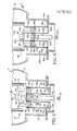
- a casting apparatus 10 (Fig. 1) includes a fluid tight housing 12 which encloses an induction furnace 14 having a cylindrical susceptor housing 16 and an induction coil 18.
- a water cooled copper chill plate 20 is mounted on a cylindrical support post 22 and is movable vertically up and down relative to the furnace 14 and housing 12 by a reversible motor 24.
- the general construction of the housing 12 and furnace 14 is well known and may be similar to that shown in U.S. Patent No. 3,841,384 issued October 15, 1974 for Method and Apparatus for Melting and Casting Metal.
- a one piece ceramic mold structure 30 is supported on the circular chill plate 20.
- the mold structure 30 includes a plurality of article molds 32 disposed in an annular array about an open central portion 34. It should be understood that although only two article molds 32 are illustrated in Fig. 1, additional article molds are arranged in a circular array in a manner similar to that disclosed in Patent Cooperation Treaty Application No. PCT/US86/00166 filed January 28, 1986 for Method and Apparatus for Casting Articles.
- the one piece ceramic mold structure 30 includes a gating system 36 which extends across an upper end of the open central portion 34 of the array of article molds 32.
- the gating system 36 includes a pour cup 38 which is connected with each of the article molds 32 by a plurality of runners 40.
- the runners 40 extend radially outwardly from the pour cup in a manner similar to that disclosed in U.S. Patent No. 3,680,625 issued August 1, 1972 for Heat Reflector and U.S. Patent No. 4,550,764 issued November 5, 1985 for Apparatus and Method for Casting Single Crystal Articles.
- a circular inner baffle plate 44 is disposed in the open central portion of the array of article molds 32 and an annular outer baffle plate 46 circumscribes the circular array of article molds.
- the inner and outer baffle plates 44 and 46 are disposed on the same level and retard the transfer of heat to the chill plate 20.
- the inner baffle plate 44 retards the transfer of heat from the article molds 32 through the open central portion 34 of the array of article molds to the chill plate 20.
- the annular outer baffle plate 46 retards the transfer of heat from the article molds 32 to the circular outer rim of the chill plate 20.
- the baffle plates 44 and 46 can be made of any desired material, for example a heat insulating and/or reflecting material. If desired, only the inner baffle plate 44 may be used with the open center mold structure 30. If the mold structure 30 has a closed center construction, only the outer baffle plate 46 may be used.
- the inner and outer baffle plates 44 and 46 are supported by a support structure 50 which extends through the chill plate 20.
- the support structure 50 supports the baffle plates 44 and 46 in a stationary relationship with the furnace housing 16 during an initial portion of the withdrawal of the mold structure 30 from the furnace 14.
- the baffle plates 44 and 46 and support structure 50 move downwardly with the chill plate 20.
- the support structure 50 extends through the chill plate 20 to support the inner and outer baffle plates 44 and 46 in a stationary and coaxial relationship with the furnace 14 until the mold structure 30 has been partially withdrawn from the furnace 14.
- the baffle plates 44 and 46 and support structure 50 then move downwardly with the chill plate 20 as the withdrawal of the mold structure 30 from the furnace 14 is completed.
- the chill plates 44 and 46 cooperate with the mold structure to provide a relatively large temperature gradient between the inside and outside of the furnace.
- the inner baffle plate 44 promotes the obtaining of the relatively large temperature gradient by blocking radiation of heat from the portions of the article molds 32 above the inner baffle plate to the chill plate 20 and the outside of the furnace 14 through the open central portion 34 of the mold structure.
- the outer baffle plate 46 promotes the obtaining of the relatively large temperature gradient by blocking the radiation of heat from the portion of the article molds disposed above the outer baffle plate to the chill plate 20 and the outside of the furnace.
- the use of the baffle plates 44 and 46 promotes the formation of horizontal isotherms with a relatively high temperature gradient for each unit length of portions of the article molds 32 as they are withdrawn from the furnace 14.
- the support structure 50 holds the inner and outer baffle plates 44 and 46 stationary relative to the furnace 14 as the chill plate 20 and mold structure 30 are continuously lowered from the raised or pouring position of Fig. 1 to withdraw the mold structure 30 from the furnace 14.
- the support structure 50 holds the inner and outer baffle plates 44 and 46 stationary and at the same level. Therefore, as the mold structure 30 is lowered, the exposure of the lower portions of the article molds 32 to the chill plate 20 through the open central portion 34 of the mold structure increases. At the same time, the exposure of the lower portions of the article molds 32 to the periphery of the chill plate 20 and to the relatively cool portion of the housing 12 outside of the furnace housing 16 increases.
- the stationary inner and outer baffle plates 44 and 46 are disposed adjacent to the upper ends of the article molds 32. Therefore heat can be transferred throughout the length of the article molds to the chill plate 20 and the outside of the furnace 14.
- the molten metal in the article molds solidifies at a controlled rate to promote directional solidification of molten metal upwardly from a lower portion to an upper portion of the article molds with the formation of equiaxed, columnar grained or single crystal cast articles.
- the inner baffle plate 44 is disposed adjacent to the upper ends of the article molds and the gating system 36.
- both the baffle plate 44 and support structure 50 are moved downwardly with the chill plate 20. This prevents interference between the inner baffle plate 44 and the gating system 36.
- the baffle plate support structure 50 is initially held stationary by retainers 54 which are fixedly connected to the housing 12. Upon engagement of the inner baffle plate 44 with the gating system 36, the downward pressure applied against the baffle plate by the gating system is transmitted through the support structure 50 to the retainers 54. This force is sufficient to cause the retainers 54 to release the support structure 50.
- the support structure 50 When the support structure 50 is released by the retainers 54, the support structure, inner baffle plate 44 and outer baffle plate 46 drop downwardly from the position shown in Fig. 4 to the position shown in Fig. 5. Downward movement of the baffle plates 44 and 46 results in the baffle plates moving from positions adjacent to the upper end portions of the article molds 32 to positions in which the baffle plates rest on the chill plate 20 and are disposed adjacent to the lower end portions of the article molds 32. During continued downward movement of the chill plate 20 from the position shown in Fig. 5, the baffle plates 44 and 46 and the support structure 50 move with the chill plate and mold structure 30. Bearings are provided between the lower end portion of the support structure 50 and post 22 to guide movement of the support structure.
- baffle plates 44 and 46 are not fixedly connected to the support structure 50, downward movement of the support structure is not stopped by engagement of the baffle plates with the chill plate 20.
- flexible straps may be connected with the chill plate 20 and support structure 50 to limit downward movement of the support structure relative to the chill plate. It is believed that the use of straps to limit downward movement of the support structure 50 will be preferred when the baffle plates 44 and 46 are formed of light weight pieces of insulating board which are not fixedly secured to the support structure.
- the continuous downward movement of the chill plate 20 completely withdraws the mold structure 30 from the furnace 14 and lowers the mold structure to a position adjacent to the lower end of the fluid tight housing 12.
- a door (not shown) at the lower end portion of the housing 12 can then be opened and the mold structure 30 removed from the housing. When this occurs, the upper end of the mold structure 30 is below the retainers 54.
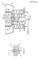
- the baffle plate support structure 50 includes a plurality of vertical support rods 58 having upper end portions 60 which are fixedly connected to the inner baffle plate 44.
- the cylindrical support rods 58 have lower end portions 62 which are fixedly connected to an annular metal base plate 64 which engages the retainers 54.
- the cylindrical support rods 58 have intermediate portions 66 which extend upwardly from the lower end portions 62 of the support rods through vertical passages 68 in the chill plate 20 to the upper end portions 60 of the support rods.
- the support rods 58 have a length which is greater than the vertical distance through which the chill plate moves from the position shown in Fig. 1 to the position shown in Fig. 4. If desired, the upper end portions 60 of the support rods 58 could merely be disposed in abutting engagement with the baffle plate 44 rather than being fixedly secured to the baffle plate.
- the cylindrical passages 68 in the chill plate 20 extend between a horizontal circular upper major side surface 70 (Fig. 3) of the chill plate 20 and parallel lower major side surface 72 of the chill plate 20.
- the support rods 58 are disposed in a circular array about the vertical central axis of the chill plate support post 22.
- the support rods 58 have longitudinal cental axes which extend parallel to the longitudinal central axis of the support post 22 and which are coincident with the central axes of the passages 68 through the chill plate 20.
- the outer baffle plate 46 is supported by a plurality of vertical support rods 78 having upper end portions 80 which are fixedly connected to the outer baffle plate 46 and lower end portions 82 which are fixedly connected to the base plate 64.
- the cylindrical support rods 78 have intermediate portions 86 which extend through vertical passages or recesses 88 formed in the rim portion of the circular chill plate 20 (Fig. 3).
- the support rods 78 have longitudinal central axes which extend parallel to the central axes of the support rods 58 and post 22.
- the central axes of the support rods 78 are coincident with central axes of the passages 88 formed in the periphery of the chill plate 20. If desired, the upper end portions 80 of the support rods 78 could merely be disposed in abutting engagement with the outer baffle plate 46.
- the support structure 50 supports both the inner baffle plate 44 and outer baffle plate 46. It is contemplated that the support structure 50 could be constructed to support only one of the baffle plates 44 or 50 when only one baffle plate is to be used. Thus, if only the inner baffle plate 44 is required, the outer baffle plate 46 and its support rods 78 could be omitted. Similarly, if only the outer baffle plate 46 is required, the inner baffle plate 44 and its support rods 58 could be omitted.
- retainers 54 could be used to hold the support structure 50 stationary relative to the furnace 14 until the gating system 36 engages the inner baffle plate 44, in one specific embodiment of the invention, the retainers were magnets.
- the magnets 54 magnetically engage the annular metal base plate 64 which is connected with the lower end portions 62 and 82 of the support rods 58 and 78.
- the magnetic retainers 54 hold the support structure 50 stationary during lowering of the chill plate 20 and mold structure 30 from the raised or pouring position of Fig. 1 to the partially withdrawn position of Fig. 4.
- the gating system 36 moves into engagement with the inner baffle plate 44.
- the force applied against the inner baffle plate 44 by the gating system 36 is transmitted to the support structure 50.
- This force is sufficient to disengage the annular metal base plate 64 from the magnetic retainers 54.
- the support structure 50 and inner and outer baffle plates 44 and 46 drop downwardly onto the chill plate 20, that is, from the position shown in Fig. 4 to the position shown in Fig. 5. At this time, the support structure 50 is supported by the baffle plates 44 and 46.
- the baffle plates 44 and 46 and support structure 50 move downwardly with the chill plate 20.
- the mold structure 30 is moved downwardly relative to the stationary baffle plates 44 and 46 through a distance equal to the vertical height of the article molds 32.
- the mold structure 30, baffle plates 44 and 46 and support structure 50 are then moved downwardly with the chill plate 20 through a distance which is greater than the vertical height of the gating system 36.
- magnets as retainer elements 54, it is contemplated that various known pressure responsive latch assemblies could be used if desired.
- the mold structure 30 would be provided with projections which would engage the outer baffle plate 46. The force applied by these projections against the outer baffle plate 46 would disengage the base plate 64 from the magnetic retainer 54. When this occurs, the support structure 50 and outer baffle plate 46 would drop downwardly.
- the illustrated support structure 50 includes a plurality of baffle plate support rods 58 and 78, it is contemplated that single support rod 58 could be provided for the inner baffle plate 44 and a single outer support rod 78 could be provided for the outer baffle plate 46. Although it is preferred to simplify the construction of the mold structure 30 by having the baffle plates 44 and 46 supported independently of members extending through the array of article molds 32, it is contemplated that the outer baffle plate 46 and/or the inner baffle plate 44 could be supported by one or more elements extending radially through the annular array of article molds 32.
- the inner and outer baffle plates 44 and 46 may be used either together or separately. However, it is believed that it will usually be preferred to use both the inner and outer baffle plates 44 and 46 together to maximize the thermal gradient between the inside and outside of the furnace 14 as the mold structure 30 is lowered. With the open center mold structure 30, it is believed that the inner baffle plate 44 will usually be necessary to obtain the desired thermal gradient.
- the baffle plates 44 and 46 were formed of pieces of insulating board. This insulating board had a thickness of approximately 0.25 inches and was formed of graphite felt enclosed by layers of graphite foil. The insulating board is commercially available from Polycarbon, Inc. under the trade name Graphfoil.
- the baffle plates 44 and 46 were not fixedly connected to the support structure 50 and downward movement of the support structure from the position of Fig. 4 to the position of Fig. 5 was limited by flexible straps connected between the support structure and chill plate 20.
- the mold structure When articles are to be cast in the mold structure 30, the mold structure is placed on the chill plate 20 while the chill plate is in a fully lowered position adjacent to the lower end of the housing 12. At this time, the baffle plates 44 and 46 are disposed in engagement with the chill plate 20 and the support structure 50 extends downwardly from the chill plate in the manner shown in Fig. 5.
- the motor 24 is then operated to move the support post 22, chill plate 20, mold structure 30 and baffle support structure 50 upwardly in the housing 12. During this upward movement, the chill plate 20 and mold structure 30 move upwardly past the retainers 54 and enter the furnace 14. As the chill plate 20 approaches the raised position of Fig. 1, the metal base plate 64 of the support structure 50 is magnetically engaged by the retainers 54 and held in place.
- the housing 12 is then sealed and evacuated.
- the induction coil 18 is then energized to preheat the mold structure 30 to a relatively high temperature, approximately 2,800° F.
- the copper chill plate 20 is cooled by a flow of liquid through the chill plate.
- the baffle plates 44 and 46 overlie the upper side surface 70 of the chill plate 20 to retard the transfer of heat from the article molds 32 to the chill plate.
- molten metal is poured into the pour cup 38 and conducted through the runners 40 to the article molds 32.
- the molten metal fills the article molds and at least a portion of the runners 40.
- the molten metal was a nickel chrome super alloy and the article molds 32 had a configuration corresponding to the configuration of turbine blades.
- the apparatus and method of the present invention could be utilized to cast different articles out of different metals.
- the motor 24 is continuously operated to lower the support post 22 and chill plate 20.
- the lower end portions of the article molds 32 move downwardly past the stationary baffle plates 44 and 46 and are exposed to the central portion of the chill plate 20 (see Fig. 2).
- the baffle plates 44 and 46 retard the transfer of heat from the upper portions of the article molds 32 to the chill plate 20 at the outside of the furnace 14.
- baffle plate support rods 58 and 78 and baffle plates 44 and 46 are held against axial movement by the retainers 54 as the chill plate 20 is lowered through a distance equal to the height of the article molds 32. Therefore, the support rods 58 and 78 have a length which is greater than the height of the article molds 32.
- the baffle plates 44 and 46 are fixedly connected to the support structure 50. Therefore, dropping the baffle plates 44 and 46 onto the chill plate 20 limits downward movement of the support structure 50.
- the baffle plates 44 and 46 could merely rest on the upper end portions 60 and 80 of the support rods 50 and 78. In such an embodiment of the invention, flexible straps would be used to limit downward movement of the support structure 50.
- the chill plate 20 and mold structure 30 continue to be lowered by operation of the motor 24. This results in the support structure 50 and baffle plates 44 and 46 moving downwardly with the mold structure 30 as the mold structure is completely withdrawn from the furnace 14. Thus, once the baffle plates 44 and 46 have dropped down onto the chill plate 20, there is no relative movement between the chill plate and the baffle plates as the chill plate continues to be lowered. The mold structure 30 with the cast articles therein is subsequently withdrawn from the lower end of the housing 12. The baffle plates 44 and 46 may then be replaced or, preferably, reused with a next succeeding mold structure.
- the speed of operation of the motor could be varied if desired.
- the motor 24 could be operated at a relatively slow speed to move the mold structure 30 to the position shown in Fig. 5. Since the molten metal will have solidified in the article molds 32, the motor 24 can then be operated at a relatively high speed to complete the withdrawal of the mold structure 30 from the furnace 14.
- the inner baffle plate 44 has been shown as being a one-piece flat plate.
- the baffle plate 44 could include a circular bottom plate and a layer of insulation on top of the bottom plate. This bottom plate may be secured to the support rods 58 or may merely rest on the support rods during downward movement of the chill plate 20.
- the amount of heat insulation provided by the baffle plate 44 can be adjusted by varying the amount of insulation provided by the baffle plate to control the rate of heat transfer from the article molds 32 to the chill plate 20 during withdrawal of the mold structure 30 from the furnace 14.
- substantially horizontal solidification fronts can be obtained in the article molds 32 as the mold structure 30 is withdrawn from the furnace 14.
- the insulating effect of the outer baffle plate 46 could be varied in a similar manner to obtain the desired horizontal solidification fronts within the article molds 32.
- the establishment of a horizontal solidification front is advantageous when casting articles having many different crystallographic structures, including equiaxed, columnar grained, and single crystal structures.
- the magnetic retainers 54 release the baffle plate support structure 50 to enable the support structure and baffle plates 44 and 46 to drop downwardly from the position shown in Fig. 4 to the position shown in Fig. 5. It is contemplated that it may be desirable to eliminate the dropping of the baffle plate support structure 50 and baffle plates 44 and 46.
- retainers connect the baffle plate support structure with the chill plate after the mold structure has been partially withdrawn from the furnace 14 to prevent the baffle plate support structure from dropping. Since the embodiment of the invention illustrated in Fig. 6 is generally similar to the embodiment of the invention illustrated in Figs. 1-5, similar numerals will be utilized to designate similar components, the suffix letter "a" being added to the numerals of Fig. 6 to avoid confusion.
- the casting apparatus 10a includes a fluid tight housing 12a which encloses an induction furnace 14a.
- a circular chill plate 20a is supported on a central post 22a which is movable vertically up and down by a motor 24a.
- a one piece mold structure 30a is supported on the chill plate 20a.
- the ceramic mold structure 30a includes an annular array of article molds 32a which extend around an open central portion 34a of the mold structure.
- a gating system 36a is connected with upper ends of the article molds 32a.
- An inner baffle plate 44a is supported in the open central portion 34a of the mold structure 30a by a support structure 50a.
- An annular outer baffle plate 46a circumscribes an annular array of article molds 32a and is supported by the support structure 50a.
- the support structure 50a extends through passages 68a and 88a formed in the chill plate 20a.
- the support structure 50a includes inner support rods 58a which support the inner baffle plate 44a and outer support rods 78a which support the outer baffle plate 46a.
- the support rods 58a and 78a are connected with an annular metal base plate 64a.
- the base plate 64a is magentically engaged by retainers 54a which hold the support structure 50a stationary until the upper end portions of the article molds 32a have been moved downwardly to a position adjacent to the inner and outer baffle plates 44a and 46a.
- annular flange 100 interconnecting the outer support rods 78a engages magnetic retainer elements 102 connected with the chill plate 20a.
- the inner baffle plate 44a is spaced a small distance from the mold gating system 36a. Therefore, when the mold structure 30a is in the raised position, corresponding to the position of the mold structure 30 in Fig. 1, the flange 100 is spaced from the retainer elements 102 by a distance which is equal to the height of the article molds 32a.
- the baffle plate support structure 50a is held against dropping downwardly by the magnetic retainers 102 which engage the annular flange 100. Therefore, during continued downward movement of the chill plate 20a and mold structure 30a, the support structure 50a and baffle plates 44a and 46a are held stationary relative to the chill plate 20a by engagement of the flange 100 with the retainers 102.
- the mold structure 30a and chill plate 20a are lowered relative to the inner and outer baffle plates 44a and 46a until the baffle plates are adjacent to the upper end portions of the article molds 32a.
- the baffle plates 44a and 46a then remain adjacent to the upper end portions of the article molds 32a as the support structure 50a and mold structure 30a are lowered with the chill plate 20a to complete the withdrawal of the mold 30a from the furnace 14a.
- each of the support rods 58 is circumscribed by an annular projection or collar 100 (Fig. 7) to keep the molten metal out of the passages through which the support rods 50 extend.
- the collar 110 is formed by a cylindrical tube which is received in a circular recess formed in the upper side 70 of the chill plate 20.
- the upwardly projecting collar 110 could be integrally formed as one piece with the chill plate 20 if desired.
- the lower side of the inner baffle plate 44 engages or is disposed immediately above the collars 110 surrounding the support rods 58.
- the inner baffle plate 44 is disposed a substantial distance above the collars 110.
- the annular outer baffle plate 46 has a circular peripheral surface which is disposed adjacent to and spaced slightly apart from the furnace housing or susceptor 16. This allows heat transfer to occur between the periphery of the outer baffle plate 46 and the furnace 14.
- the outer baffle plate engages the bottom of the furnace to retard a transfer of heat between the periphery of the outer baffle plate and the furnace. Since the embodiment of the invention illustrated in Fig. 8 is generally similar to the embodiment of the invention illustrated in Figs. 1-6, similar numerals will be utilized to identify similar components, the suffix letter "b" being associated with the components of Fig. 8 to avoid confusion.
- a casting apparatus 10b includes a fluid tight housing 12b which encloses an induction furnace 14b having a susceptor housing 16b and an induction coil 18b.
- a water cooled copper chill plate 20b is mounted on a cylindrical support post 22b and is movable vertically up and down relative to the furnace 14b and housing 12b by a reversible motor 24b.
- a one piece ceramic mold structure 30b is supported on the circular chill plate 20b.
- a mold structure 30b includes a plurality of article molds 32b disposed in an annular array about an open central portion 34b.
- the one piece ceramic mold structure 30b includes a gating system 36b having a pour cup 38b.
- a circular inner baffle plate 44b is disposed in the open central portion of the array of article molds 32b.
- An annular outer baffle plate 46b circumscribes the circular array of article molds 32b.
- the inner and outer baffle plates 44b and 46b are supported by a support structure 50b which extends through the chill plate 20b.
- the support structure 50b supports the baffle plates 44b and 46b in a stationary relationship with the furnace housing 16b during an initial portion of the withdrawal of the mold structure 30b from the furnace 14b. During a final portion of the withdrawal of the mold structure 30b from the furnace 14b, the baffle plates 44b and 46b and support structure 50b move downwardly with the chill plate 20b in the same manner as previously described in conjunction with the embodiments of the invention illustrated in Figs. 1-6.
- the outer baffle plate 46b engages the bottom of the furnace 14b to retard heat transfer between the inside and outside of the furnace.
- the outer baffle plate 46b has a flat annular upper surface which engages a flat annular lower surface of the susceptor housing 16b to block the transfer of heat around the outer rim of periphery of the baffle plate 46b.
- the mold structure When articles are to be cast in the mold structure 30b, the mold structure is placed on the chill plate 20b while the chill plate is in a fully lowered position. At this time, the baffle plates 44b and 46b are disposed in engagement with the chill plate 20b. The motor 24b is then operated to move the chill plate 20b, mold structure 30b and baffle plate support structure 50b upwardly in the housing 12b. As the chill plate 20b approaches the raised position shown in Fig. 8, the metal base plate 64b of the support structure 50b is magentically engaged by the retainers 54b and held in place. At the same time, the upper surface of the outer chill plate 46b moves into abutting engagement with the lower surface of the susceptor housing 16b in the manner shown in Fig. 8.
- the mold structure 30 is preheated. Molten metal is then poured into the pour cup 38b and fills the article molds 32b.
- the motor 24b is then continuously operated to lower the support post 22b and chill plate 20b. As the mold structure 30b is lowered with the chill plate 20b, the lower end portions of the article molds 32b move downwardly past the stationary baffle plates 44b and 46b.
- the inner baffle plate 44b retards the transfer of heat from the portion of the article molds 32b in the furnace 14b to the central portion of the chill plate.
- the outer baffle plate 46b retards the transfer of heat from the portion of the article molds in the furnace to the rim of the chill plate and the relatively cool interior of the housing 12b. Since the outer baffle plate 46b is held in engagement with the bottom of the furnace 14b by the support structure 50b, the transfer of heat from the inside of the furnace 14b around the periphery of the outer baffle plate 46b is blocked.
- the outer baffle plate 46b is used with an inner baffle plate 44b in association with an open center mold structure 30b. It is contemplated that the outer baffle plate 46b may be used in conjunction with mold structures which do not have an open center construction. Under these circumstances, the inner baffle plate 44b could be omitted.
- the outer baffle plate 46b engage the bottom of the furnace susceptor housing 16b, the establishment of a relatively large heat gradient between the inside of the funace 14b and the outside of the furnace is promoted with either an open center or a closed center mold structure.
- the present invention provides a new and improved method and apparatus for use in casting a plurality of articles in a mold structure 30 having a plurality of article molds 32 disposed in an array with an open central portion 34.
- An inner baffle plate 44 is disposed in the open central portion 34 of the mold structure 30 to retard the transfer of heat from the article molds 32 to the chill plate 20 during preheating of the mold structure and pouring of molten metal into the mold structure.
- An outer baffle plate 46 is disposed around the outside of the mold structure 30. Although it is preferred to use both the inner and outer baffle plates 44 and 46, either baffle plate may be used by itself.
- the mold structure 30 As the mold structure 30 is withdrawn from the furnace 14, the mold structure is lowered from a position (Fig. 1) in which the baffle plates 44 and 46 are adjacent to the lower end portion of the article molds 32 to a position (Fig. 4) in which the baffle plates are adjacent to the upper end portions of the article molds.
- the stationary inner baffle plate 44 retards the transfer of heat through the open central portion 34 of the mold structure 30.
- the stationary outer baffle plate 46 may be pressed against a lower end portion of the furnace 14 to retard the transfer of heat around the outside of the mold structure 30b (see Fig. 8).
- the baffle plate or plates 44 and/or 46 are supported by a stationary support structure 50 which extends through the chill plate 20.
- the baffle plate or plates 44 and/or 46 and support structure 50 move downwardly with the chill plate 20.
- the baffle plates 44 and/or 46 and support structure 50 are stationary during an initial portion of the withdrawal of the mold structure 30 from the furnace 14.
- the baffle plates 44 and/or 46 and support structure 50 move downwardly with the chill plate 20.
- the mold structure can have a central gating system 36 which extends across the upper end of the open central portion 34 of the mold structure to promote an even distribution of molten metal to the various article molds 32.
Applications Claiming Priority (2)
| Application Number | Priority Date | Filing Date | Title |
|---|---|---|---|
| US07/013,469 US4763716A (en) | 1987-02-11 | 1987-02-11 | Apparatus and method for use in casting articles |
| US13469 | 1998-01-26 |
Publications (2)
| Publication Number | Publication Date |
|---|---|
| EP0278762A2 true EP0278762A2 (fr) | 1988-08-17 |
| EP0278762A3 EP0278762A3 (fr) | 1989-02-01 |
Family
ID=21760120
Family Applications (1)
| Application Number | Title | Priority Date | Filing Date |
|---|---|---|---|
| EP88301136A Withdrawn EP0278762A3 (fr) | 1987-02-11 | 1988-02-11 | Appareil et procédé à l'usage en coulée d'articles |
Country Status (3)
| Country | Link |
|---|---|
| US (1) | US4763716A (fr) |
| EP (1) | EP0278762A3 (fr) |
| JP (1) | JPS63248562A (fr) |
Cited By (4)
| Publication number | Priority date | Publication date | Assignee | Title |
|---|---|---|---|---|
| GB2309405A (en) * | 1996-01-25 | 1997-07-30 | Ald Vacuum Techn Gmbh | Casting and directional solidification using a heat sink |
| EA000040B1 (ru) * | 1995-06-20 | 1998-02-26 | Абб Рисерч Лтд | Способ изготовления литьевой заготовки в вакуумной камере и устройство для осуществления этого способа |
| US6896030B2 (en) | 2003-07-30 | 2005-05-24 | Howmet Corporation | Directional solidification method and apparatus |
| EP3346030A1 (fr) * | 2017-01-09 | 2018-07-11 | Safran | Installation pour la fabrication d'une piece par mise en oeuvre d'un procede bridgman |
Families Citing this family (10)
| Publication number | Priority date | Publication date | Assignee | Title |
|---|---|---|---|---|
| US4969501A (en) * | 1989-11-09 | 1990-11-13 | Pcc Airfoils, Inc. | Method and apparatus for use during casting |
| US6557618B1 (en) | 1997-09-12 | 2003-05-06 | General Electric Company | Apparatus and method for producing castings with directional and single crystal structure and the article according to the method |
| US6276432B1 (en) | 1999-06-10 | 2001-08-21 | Howmet Research Corporation | Directional solidification method and apparatus |
| DE60017850T2 (de) | 1999-10-26 | 2006-05-11 | Matsushita Electric Industrial Co., Ltd., Kadoma | Verfahren zur Herstellung eines wiederverwendeten Pulvers für die Benutzung in einem Verbundmagnet und Verfahren zur Wiederverwendung eines Verbundmagneten |
| US6637499B2 (en) | 2002-02-06 | 2003-10-28 | Retech Systems Llc | Heat shield with adjustable discharge opening for use in a casting furnace |
| US6651728B1 (en) | 2002-07-02 | 2003-11-25 | Pcc Airfoils, Inc. | Casting articles |
| US6698493B2 (en) * | 2002-07-23 | 2004-03-02 | Pcc Airfoils, Inc. | Apparatus and method for casting a metal article |
| US6827124B2 (en) * | 2002-10-29 | 2004-12-07 | Pcc Airfoils, Inc. | Method and apparatus for use during casting |
| US6889747B2 (en) | 2003-03-04 | 2005-05-10 | Pcc Airfoils, Inc. | Fluidized bed with baffle |
| US7000675B2 (en) * | 2003-04-09 | 2006-02-21 | Tooling And Equipment International | Chill assembly |
Citations (4)
| Publication number | Priority date | Publication date | Assignee | Title |
|---|---|---|---|---|
| US3810504A (en) * | 1971-03-26 | 1974-05-14 | Trw Inc | Method for directional solidification |
| DE2815818A1 (de) * | 1977-04-21 | 1978-10-26 | United Technologies Corp | Giessgeraet fuer die gerichtete erstarrung von schmelzfluessigem metall |
| DE2911625A1 (de) * | 1978-03-31 | 1979-10-04 | Gen Electric | Ofen zum giessen mit gerichteter erstarrung |
| US4550764A (en) * | 1983-12-22 | 1985-11-05 | Trw Inc. | Apparatus and method for casting single crystal articles |
Family Cites Families (4)
| Publication number | Priority date | Publication date | Assignee | Title |
|---|---|---|---|---|
| US3690368A (en) * | 1970-08-14 | 1972-09-12 | United Aircraft Corp | Casting single crystal articles |
| US3714977A (en) * | 1971-07-23 | 1973-02-06 | United Aircraft Corp | Method and apparatus for the production of directionally solidified castings |
| EP0185058B1 (fr) * | 1984-06-15 | 1991-10-09 | AT&T Corp. | Compose encapsulant et articles le comportant |
| US4673021A (en) * | 1986-01-28 | 1987-06-16 | Trw Inc. | Method and apparatus for casting articles |
-
1987
- 1987-02-11 US US07/013,469 patent/US4763716A/en not_active Expired - Lifetime
-
1988
- 1988-02-11 EP EP88301136A patent/EP0278762A3/fr not_active Withdrawn
- 1988-02-12 JP JP63030668A patent/JPS63248562A/ja active Granted
Patent Citations (4)
| Publication number | Priority date | Publication date | Assignee | Title |
|---|---|---|---|---|
| US3810504A (en) * | 1971-03-26 | 1974-05-14 | Trw Inc | Method for directional solidification |
| DE2815818A1 (de) * | 1977-04-21 | 1978-10-26 | United Technologies Corp | Giessgeraet fuer die gerichtete erstarrung von schmelzfluessigem metall |
| DE2911625A1 (de) * | 1978-03-31 | 1979-10-04 | Gen Electric | Ofen zum giessen mit gerichteter erstarrung |
| US4550764A (en) * | 1983-12-22 | 1985-11-05 | Trw Inc. | Apparatus and method for casting single crystal articles |
Cited By (10)
| Publication number | Priority date | Publication date | Assignee | Title |
|---|---|---|---|---|
| EA000040B1 (ru) * | 1995-06-20 | 1998-02-26 | Абб Рисерч Лтд | Способ изготовления литьевой заготовки в вакуумной камере и устройство для осуществления этого способа |
| GB2309405A (en) * | 1996-01-25 | 1997-07-30 | Ald Vacuum Techn Gmbh | Casting and directional solidification using a heat sink |
| US5778961A (en) * | 1996-01-25 | 1998-07-14 | Ald Vacuum Technologies Gmbh | Process and device for simultaneous casting and directional solidification of several castings |
| GB2309405B (en) * | 1996-01-25 | 1999-03-24 | Ald Vacuum Techn Gmbh | Process and device for simultaneous casting and directional solidification of several castings |
| US6896030B2 (en) | 2003-07-30 | 2005-05-24 | Howmet Corporation | Directional solidification method and apparatus |
| EP3346030A1 (fr) * | 2017-01-09 | 2018-07-11 | Safran | Installation pour la fabrication d'une piece par mise en oeuvre d'un procede bridgman |
| FR3061722A1 (fr) * | 2017-01-09 | 2018-07-13 | Safran | Installation pour la fabrication d'une piece par mise en oeuvre d'un procede bridgman |
| CN108286068A (zh) * | 2017-01-09 | 2018-07-17 | 赛峰集团 | 通过实施布里奇曼法来制造零件的设备 |
| US10562096B2 (en) | 2017-01-09 | 2020-02-18 | Safran | Installation for manufacturing a part by implementing a Bridgman method |
| CN108286068B (zh) * | 2017-01-09 | 2021-02-26 | 赛峰集团 | 通过实施布里奇曼法来制造零件的设备 |
Also Published As
| Publication number | Publication date |
|---|---|
| US4763716A (en) | 1988-08-16 |
| JPH0525591B2 (fr) | 1993-04-13 |
| JPS63248562A (ja) | 1988-10-14 |
| EP0278762A3 (fr) | 1989-02-01 |
Similar Documents
| Publication | Publication Date | Title |
|---|---|---|
| US4763716A (en) | Apparatus and method for use in casting articles | |
| US4108236A (en) | Floating heat insulating baffle for directional solidification apparatus utilizing liquid coolant bath | |
| US3714977A (en) | Method and apparatus for the production of directionally solidified castings | |
| US4774992A (en) | Apparatus and method for use in casting a plurality of articles | |
| US6510889B2 (en) | Directional solidification method and apparatus | |
| US3841384A (en) | Method and apparatus for melting and casing metal | |
| US3620289A (en) | Method for casting directionally solified articles | |
| US5607007A (en) | Directional solidification apparatus and method | |
| EP1375034A2 (fr) | Procédé et dispositif pour la coulée par solidification dirigée de métal en fusion | |
| GB1369270A (en) | Casting of directionally solidified articles | |
| CA2014504C (fr) | Fusion des metaux, par induction, sans l'emploi d'un creuset | |
| US4773467A (en) | Method and apparatus for casting articles | |
| US4202400A (en) | Directional solidification furnace | |
| US4673021A (en) | Method and apparatus for casting articles | |
| US3754592A (en) | Method for producing directionally solidified cast alloy articles | |
| WO1997046742A9 (fr) | Procede et dispositif pour la fabrication de fonte en solidification dirigee | |
| KR20000016339A (ko) | 방향성 고화 주물 제조 방법 및 장치_ | |
| US5309976A (en) | Continuous pour directional solidification method | |
| US3633648A (en) | Method of casting in investment molds having a radiation shield | |
| US20100206510A1 (en) | Method and apparatus for casting metal articles | |
| US4757856A (en) | Method and apparatus for casting articles | |
| US6651728B1 (en) | Casting articles | |
| US4683936A (en) | Controlled solidification, method of distributing strengthening additives and maintaining a constant melt level | |
| EP0256002A4 (fr) | Lingotiere, procede et appareil de moulage d'articles. | |
| US4922992A (en) | Melt-holding vessel and method of and apparatus for countergravity casting |
Legal Events
| Date | Code | Title | Description |
|---|---|---|---|
| PUAI | Public reference made under article 153(3) epc to a published international application that has entered the european phase |
Free format text: ORIGINAL CODE: 0009012 |
|
| AK | Designated contracting states |
Kind code of ref document: A2 Designated state(s): DE FR GB |
|
| PUAL | Search report despatched |
Free format text: ORIGINAL CODE: 0009013 |
|
| AK | Designated contracting states |
Kind code of ref document: A3 Designated state(s): DE FR GB |
|
| 17P | Request for examination filed |
Effective date: 19890503 |
|
| 17Q | First examination report despatched |
Effective date: 19900215 |
|
| STAA | Information on the status of an ep patent application or granted ep patent |
Free format text: STATUS: THE APPLICATION IS DEEMED TO BE WITHDRAWN |
|
| 18D | Application deemed to be withdrawn |
Effective date: 19911007 |